Table of Contents
Advertisement
Advertisement
Table of Contents

Related Manuals for Megger LTW315


Summary of Contents for Megger LTW315
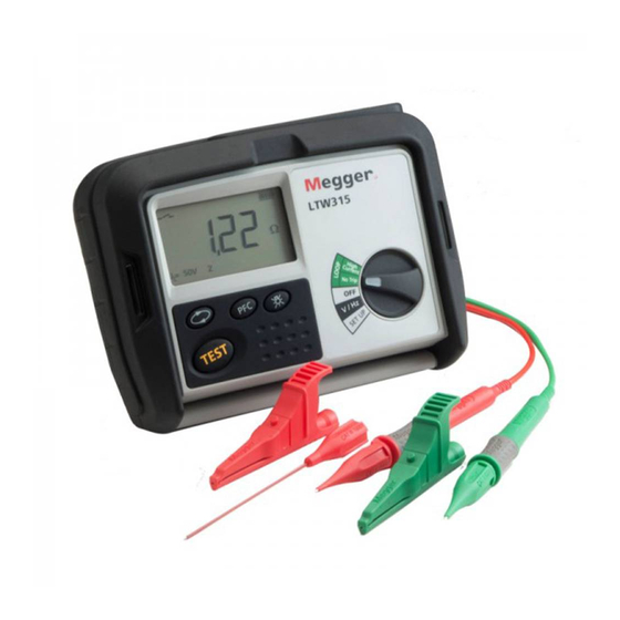
- Page 1 LTW300 Series Earth Loop testers User Guide...
-
Page 2: Safety Warnings
Safety warnings: Safety Warnings and Precautions must be read and understood before the instrument is used. They must be observed during use. The earth loop impedance test creates a temporary low resistance path between live and earth for the duration of the test. -
Page 3: Table Of Contents
Contents Introduction General introduction Unpacking the carton LCD display Top panels Additional controls on the LTW335 Keypad controls Range knob controls Connection panel Lid open/closure Preparations for use Preliminary test lead Ingress moisture General operating instructions Backlight operation Test leads Test lead connection Loop testing Description of test methods... -
Page 4: Introduction
This user guide describes the operation and functions of the following LTW300 series of loop impedance testers: LTW315 LTW325 LTW335 LTW425 These instruments are designed and manufactured by: Megger Limited Archcliffe Road Dover Kent CT17 9EN England Megger reserves the right to change the specification of these instruments at any time without prior notice. -
Page 5: General Introduction
Unpack the carton contents carefully. There are important documents that you should keep for future reference. Please complete the pre-paid warranty card and return it to Megger as soon as possible to help us reduce any delays in supporting you should the need arise. -
Page 6: Lcd Display
2.2 LCD display Fuse Blown Wait Temperature warning Refer to User manual Test Lead NULLED Indicator RCD Trip Battery status Indicator Measured results Ranges Touch voltage selected Supply noise warning R1+R2 Function Loop test extended Zref function selected Loop test selected (Mode 2 operation) active... -
Page 7: Top Panels
2.3 Top panels Test lead connections Loop test function: See section 2.5 (all except LTW315) MaxZ LCD Display R1+R2 Zref Setup function select Neck strap slots Test button Range selector: NO-TRIP High Current HIGH Res (LTW425) Volts/Frequency Setup PFC display... -
Page 8: Additional Controls On The Ltw335
2.4 Additional controls on the LTW335 (storage and downloading instrument): 2.4.1 Keypad controls UP/DOWN arrows: Scrolls through circuit and Aborts a result save distribution board numbers Confirms a test result delete process request NEXT Selects test type Job, Distribution board, Circuit, Phase etc STORE... -
Page 9: Connection Panel
2.5 Connection panel Single or 3 Phase Earth, Neutral or 2 phase connection connection Maximum 300V Warning USB connection to Phase to earth Read user guide computer port LTW335 only 2.6 Lid open/closure 1. Open lid by lifting up front panel tab (1). 2. -
Page 10: Preparations For Use
The mains plug test lead supplied with the Megger Tester is a test lead that forms part of the measuring circuit of the instrument. The overall length of this lead should not be altered. However if the power cord plug is not suitable for your type of socket outlets, do not use an adapter. -
Page 11: Test Lead Connection
WARNING: A plug severed from the power cord must be destroyed, as a plug with bare conductors is hazardous in a live socket outlet. 4.3 Test lead connection The supplied test leads should be connected to the appropriate sockets on the rear of the instrument marked L0/L2 and L1. -
Page 12: Loop Testing
Different loop testing options are available depending on the instrument used as below: Instrum NO-TRIP High MaxZ HIGH Result storage 50 V 100 V Current R1+R2 Resolution download. 440V 280 V LTW315 LTW325 LTW335 ... -
Page 13: High Current Test (All Instruments)
5%. ALL TESTS WILL OPERATE PHASE TO EARTH, PHASE TO NEUTRAL AND PHASE TO PHASE. NOTE: THE LTW315 IS NOT RATED FOR PHASE TO PHASE MEASUREMENTS ON 240 VOLTS TO EARTH SYSTEMS 5.2 Performing a loop test Note: Factory settings for the instrument are:... -
Page 14: No-Trip Loop Testing Using The Red/Green Test Lead
5.2.3 No-trip loop testing using the RED/GREEN test leads The [No-Trip] loop test can be carried out where a power socket is not available using the 2 wire lead set. 5.2.3.1 Phase to earth loop test Select the [No Trip] test range on the lower range knob, and [Z] on the upper range knob where present. Connect the RED and GREEN test leads to the instrument. -
Page 15: High Current Phase To Phase Loop Test
NOTE: Both the High current and No Trip loop tests will operate Phase to Phase. 5.4 High resolution loop test [High Resolut] (LTW425 only) The [High Resolut] Loop test performs a 2-wire high current loop test, providing a loop test result to one milliohm (0.001 Ω) resolution. -
Page 16: Maxz (Ltw325, Ltw335 And Ltw425)
5.6 Possible sources of error The displayed reading depends on a measurement of the supply voltage and therefore noise or transients caused by other equipment during the test could cause an error in the reading. One way to check for these is to do two tests and look for any difference in value. The instrument may detect some sources of noise and warn the user. -
Page 17: Measuring Zref
Application note for Zref and R1+R2 measurement: On initial verification of a new electrical installation, the value for R1+R2 should be obtained by continuity testing methods (dead testing) as per BS 7671:2001 or other international standards. For periodic inspection reports (PIR) where it is not possible to isolate the supply, the user should first verify the Circuit Protective Conductor (standard practice) prior to using the Zref and R1+R2 function on the instrument. -
Page 18: Saving And Downloading Test Results (Ltw335 Only)
Alternatively the instrument can be connected Phase to Neutral to measure the Phase-Neutral voltage. 6.2 Phase to Phase voltage and frequency measurement Set the instrument to the [V/Hz] range. Connect the GREEN test lead to one phase and the RED test lead to another phase. The instrument will display the voltage and the frequency. -
Page 19: Downloading Results To A Pc
Repeat from step 3 to recall other test records. 7.5 Downloading results to a PC: Run Megger PowerSuite Professional or Megger Download Manager on the PC. Select the appropriate downloading instrument from the list. Ensure the LTW300 driver is selected (ie MIT/LTW/RCDT) and NOT (MIT/LT/RCDT) Select "Download"... -
Page 20: Setup Menu
NOTE: The high current loop test should be used for this adjustment to ensure accurate measurements. Ensure the top range knob is set to [Z] (does not apply to the LTW315). Select the High Current test range on the instrument lower range knob. -
Page 21: Backlight Brightness Adjust
If the result is negative, the second lead set resistance is less that the standard supplied lead set and should not be used for loop testing on this instrument. If the result is greater than 0.99 Ω, the instrument will not be able to take fully into account of the extra lead resistance. -
Page 22: Warning And Status Messages
9. Warning and status messages 9.1 Loop test inhibit or premature termination of a loop test: A loop test may stop or even be prevented from starting if there is a connection problem with the test leads or instrument fuse, an earth problem on the circuit being tested, or a supply voltage or frequency out of range. Test inhibit If an out of range voltage or frequency exists on the circuit under test, testing will be automatically inhibited and the corresponding information will be displayed. -
Page 23: Replacing Batteries And Fuses
Faulty, stuck key or switch position. Loop test result out of display range. Over voltage warning. For LTW315 the warning will be <280 V. No Zref value stored, or test result lower than stored Zref. Zref measurement required before an R1+R2 measurement can be made. -
Page 24: Procedure To Replace Batteries
This will only happen if a serious internal fault has occurred. Please contact Megger Limited at the contact address at the end of this guide, or call Technical support on +44 (0)1304 502 102 for further assistance. -
Page 25: Technical Specification
Accuracy: Frequency measurement Range: 25 Hz to 99.99 Hz ±0.1 Hz Accuracy: Loop testing NO-TRIP loop and high current loop test (LTW315) Source voltage: 100 V to 280 V (50 Hz) Display range: 0.01 to 2000 ±5% ±0.03 @ 230 V a.c. ±10% ±0,03 Ω @ 100 V a.c. and 280 V a.c. -
Page 26: Accessories
Equipment for testing, measuring or monitoring of protective measures: Part1-General Requirements Part3-Loop resistance E.M.C. In accordance with IEC61326-1 Operational uncertainties: Refer to www.megger.com Power supply Battery: 8 x 1,5 V cells IEC LR6 type (AA alkaline). Rechargeable: 8 x 1.2V NiMH cells... -
Page 27: Repair And Warranty
Fax: +44 (0) 1304 207342 Fax: +1 610 676 8625 Megger operate fully traceable calibration and repair facilities, ensuring your instrument continues to provide the high standard of performance and workmanship you expect. These facilities are complemented by a worldwide network of approved repair and calibration companies which offer excellent in-service care for your Megger products. - Page 28 T +1 416 298 6770 F +1 416 298 0848 E casales@megger.com Megger products are distributed in 146 countries worldwide. This instrument is manufactured in the United Kingdom. The company reserves the right to change the specification or design without prior notice.
Need help?
Do you have a question about the LTW315 and is the answer not in the manual?
Questions and answers