Table of Contents
Advertisement
Quick Links
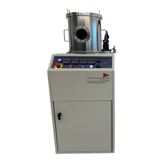
PDS 2010 LABCOTER™ 2
Parylene Deposition System
Operator's Manual
System Serial Number: ________________
Prepared for: ________________________
Make certain that everyone associated with this instrument
becomes knowledgeable about the material contained in this manual
before using the equipment.
7645 Woodland Drive, Indianapolis, IN 46278-2707
Customer Service: P 317. 244.1200 F 317.240.2073
E
SCScustomerservice@SCScoatings.com
COPYRIGHT SPECIALTY COATING SYSTEMS
Advertisement
Table of Contents

Related Manuals for SCS LABCOTER 2


Summary of Contents for SCS LABCOTER 2
- Page 1 PDS 2010 LABCOTER™ 2 Parylene Deposition System Operator’s Manual System Serial Number: ________________ Prepared for: ________________________ Make certain that everyone associated with this instrument becomes knowledgeable about the material contained in this manual before using the equipment. 7645 Woodland Drive, Indianapolis, IN 46278-2707 Customer Service: P 317.
- Page 2 Rev 37 Operator’s Manual OM-610-1002-1 7645 WOODLAND DRIVE, - INDIANAPOLIS, IN 46278-2707 – PH. 800-356-8260 SERIAL NO. MODEL NO. VOLTS AMPS PHASE INT. CAPACITY AMP MFG. DATE SCHEMATICS...
- Page 3 OM-610-1002-1 Operator’s Manual Rev 37...
- Page 4 Rev 37 Operator’s Manual OM-610-1002-1...
-
Page 5: Table Of Contents
4.10 TUMBLER (O ) ........................11 PTION 4.11 CONNECT AND CHECK ......................11 4.12 ON SITE SERVICE PROVIDED BY SCS CUSTOMER SERVICE (O ) ...... 12 PTIONAL SECTION 5 OPERATION ........................13 PURPOSE OF EQUIPMENT....................... 13 VACUUM CONCEPTS ....................... 13 5.2.1 Vacuum ............................ - Page 6 Rev 37 Operator’s Manual OM-610-1002-1 PROCESS CONTROLLERS ....................... 22 5.5.1 Furnace Temperature Controller....................22 5.5.2 Chamber Gauge Temperature Controller..................22 5.5.3 Vacuum Pressure Controller ......................22 5.5.4 Vaporizer Temperature Controller ....................23 5.5.5 Alarm............................. 23 5.5.6 Furnace / Chamber Gauge Switch....................24 5.5.7 Vacuum Switch..........................
- Page 7 OM-610-1002-1 Operator’s Manual Rev 37 6.2.5 Feed-Thru Rebuild ........................40 PROCESS TEMPERATURE CONTROLLERS................41 6.3.1 Verifying the WEST Model 6100+ Temperature Controller............42 6.3.2 Vacuum Controller........................42 6.3.3 Calibrating the Granville-Phillips Zero Pressure Simulator............43 6.3.4 Verifying the WEST Model 6100+ Vacuum Process Controller........... 43 6.3.5 Vacuum Amplifier Circuit Board Calibration................
- Page 8 Rev 37 Operator’s Manual OM-610-1002-1 SECTION 9 STEP BY STEP PROCEDURE FOR PARYLENE COATING ......111 PREPARING TO COAT ......................111 AUTO MODE OPERATION ..................... 114 SECTION 10 LIMITED WARRANTY POLICY ................117 SECTION 11 TECHNICAL LITERATURE ..................119 SECTION 12 ELECTRICAL SCHEMATICS .................. 121 ES-610-1001-2 CE ELECTRICAL SCHEMATIC (1 OF 2) ..............
-
Page 9: Safety
OM-610-1002-1 Operator’s Manual Rev 37 SECTION 1 SAFETY This equipment is designed to be used in the specific manners designated. Key elements in the design promote operator safety and assure that there will be no damage to the product being coated. The equipment complies with all applicable sections of NFPA Article 79 of the National Electric code (NEC). -
Page 10: Vaporizer And Pyrolysis Section
Material Safety Data Sheets (MSDS) are included at the end of this Safety section for user reference only. Contact your Material Safety Manager for complete updated MSDS sheets. The most up-to-date Parylene MSDS’s are available on the SCS website (www.scscoatings.com) in the technical library. The Material Safety Data Sheets cover the following topics: •... -
Page 11: Dimer Loading Door
OM-610-1002-1 Operator’s Manual Rev 37 glasses, gloves, and a dust half-mask for handling and shipping activities. This will provide protection in case the rigid skin is breached and the interior material becomes airborne. If any of the material, most likely next to the heating elements, reaches 1000°C, a chemical change takes place that forms cristobalite. -
Page 12: Servicing
Rev 37 Operator’s Manual OM-610-1002-1 SERVICING Before servicing, remove all power. If it becomes necessary to perform diagnostic service with certain areas of the machine powered, only qualified personnel should perform the service. Follow all normal industrial safety practices when dealing with electrical systems. Review and understand the electrical schematic before attempting any electrical diagnostic service. -
Page 13: Overview
OM-610-1002-1 Operator’s Manual Rev 37 SECTION 2 OVERVIEW The Labcoter™ 2 (PDS 2010) is the first portable Parylene coater of its kind. It is designed for the occasional Parylene user, and is ideal for experimentation and small production runs. The Labcoter™ 2 weighs 170 lb. and is powered by either 100, 110, or 220 VAC with 20, 18, or 12 amp service. - Page 14 Rev 37 Operator’s Manual OM-610-1002-1 page 6 SECTION 2 OVERVIEW PDS-2010...
-
Page 15: Equipment Specification
OM-610-1002-1 Operator’s Manual Rev 37 SECTION 3 EQUIPMENT SPECIFICATION PDS-2010 Dimensions Width 19.5 in (49.5cm) (Nominal) Height 50.5 in (128.3cm) Depth 23.75 in (60.4cm) Operating An ambient temp or 60–80°F is desired. Temperatures above 90°F will decrease Environment coating efficiency and may cause electric equipment to shut down. Relative Humidity should be kept between 5%–95%. - Page 16 Rev 37 Operator’s Manual OM-610-1002-1 Figure 1: Facilities Drawing Figure 2: Useable Chamber Size page 8 SECTION 3 EQUIPMENT SPECIFICATION PDS-2010...
-
Page 17: Installation
If an SCS Installation/Start-up service call is scheduled, the customer’s installation must be completed before the arrival of the SCS service technician. The customer is requested to give a minimum one-week notice for the scheduled service calls. -
Page 18: Equipment Placement
OM-610-1002-1 Open all shipping cartons. Use the shipping documents to verify that the shipment is complete. If any item is missing, or if there is trouble identifying any item, notify SCS Customer Service immediately. Make sure that you have the ship kit, which includes: Oil, Microsoap, baffle & stud, tape, and the dimer boat form. -
Page 19: Chiller (Option)
The PDS 2010 has been wired to accept the voltage and frequency requirement specified on the original purchase order. If this should change, contact the SCS Customer Service department for instructions to change the control transformer primary side wiring connections. -
Page 20: On Site Service Provided By Scs Customer Service (Optional)
Operator’s Manual OM-610-1002-1 4.12 ON SITE SERVICE PROVIDED BY SCS CUSTOMER SERVICE (Optional) Check all facility services for correct values before operating the system. Turn the system power on and systematically verify proper operation of all functions. Verify proper operation of Emergency Stop pushbutton. -
Page 21: Operation
OM-610-1002-1 Operator’s Manual Rev 37 SECTION 5 OPERATION PURPOSE OF EQUIPMENT The PDS 2010 is a vacuum system used for the vapor deposition of the Parylene polymer onto a variety of substrates. The clear polymer coating formed provides an extremely effective chemical and moisture barrier with high dielectric and mechanical strength. -
Page 22: Vacuum Levels
Rev 37 Operator’s Manual OM-610-1002-1 TABLE 5-1 Equivalence Table for Pressure/Vacuum Measurement Vacuum Torr milliTorr PSIA Inches Hg Atmosphere Atmosphere 760 000 14.7 29.92 100 000 1.93 3.94 0.132 1000 0.019 0.0394 0.00132 1.93x10 -3 3.94x10 -3 1.32x10 -4 Med. 0.100 1.93x10 -4 3.94x10 -4... -
Page 23: Outgassing
OM-610-1002-1 Operator’s Manual Rev 37 is determined by the mean free path of the enclosed gas molecules and the dimensions of the container or pipe diameter. 5.2.5.1 Mean Free Path The mean free path is basically the average distance that a gas molecule will travel before colliding with another gas molecule. -
Page 24: Base Pressure
The SCS convention is that whenever base pressure is used, it is understood to be hot base pressure. If other components in the system are heated, these conditions must be clearly explained and understood. - Page 25 The associated pressure rise during deposition is quite low. If the use of Parylene D is required for your application, contact SCS Engineering for special process considerations involved with its use in the 2010.
-
Page 26: Parylene Deposition
Rev 37 Operator’s Manual OM-610-1002-1 5.3.2 Parylene Deposition 5.3.2.1 General Parylene is formed (deposited) in place directly from a rarefied atmosphere of gaseous monomer. There is no intermediate liquid phase and no "cure" cycle. The deposition and formation of Parylene on a substrate can be viewed as a condensation process taking place in a room temperature vacuum chamber. - Page 27 OM-610-1002-1 Operator’s Manual Rev 37 Di-para-xylylene Para-xylylene Poly-(para-xylylene) (Dimer) (Monomer) (Polymer) 150° C 690° C 25° C 0.001 Torr -90° C 0.1 Torr 0.5 Torr 0.05 Torr PYROLYZE VAPORIZE POLYMERIZE DEPOSIT Vaporizer Pyrolysis Furnace Deposition Chamber Cold Trap Vacuum Pump Figure 4: Parylene Deposition Process The Parylene coating system is a sealed system consisting of tubes and chambers that allow gas to flow from the vaporizer section, through the pyrolysis zone, into the deposition chamber, past the probe cold trap, and...
- Page 28 Rev 37 Operator’s Manual OM-610-1002-1 WARNING: The pyrolysis zone has been preheated to approximately 690°C and the probe cold trap has been pre-cooled to less than -90°C. The vacuum pump is running and continuously pumping the system throughout the coating cycle. Once system base pressure has been reached in step three, the vaporizer zone is heated to 120- 180°C.
-
Page 29: Control Panel
OM-610-1002-1 Operator’s Manual Rev 37 5.3.2.5 Typical Process Settings (many factors affect this; yours may be different) Parylene Vapor Heater. Set Point Pressure Set Point Pyrolysis Heater Set Point Type N 160 C Base + 55 Vacuum 650 C Units Type C 175 C Base +15 Vacuum... -
Page 30: Process Controllers
Rev 37 Operator’s Manual OM-610-1002-1 Power If main power is applied, the white Main Power pushbutton light will illuminate. To energize the machine, depress the white Main Power pushbutton light. This will initialize the computer for operation and power the process controllers. -
Page 31: Vaporizer Temperature Controller
OM-610-1002-1 Operator’s Manual Rev 37 For more information regarding the vacuum controller values, refer to the WEST controller and Granville- Phillips gauge documentation provided in Section 6. Remember: The displayed process value is very near the actual milliTorr value while in the range of process control (10 to 100 milliTorr). The vacuum controller set point value is factory-set at 15 units above base pressure. -
Page 32: Furnace / Chamber Gauge Switch
Rev 37 Operator’s Manual OM-610-1002-1 5.5.6 Furnace / Chamber Gauge Switch If the PROCESS START/STOP button is depressed and active (the green button is lit), the Furnace/Chamber Gauge switch provides power to the furnace and chamber gauge controller outputs, which in turn provide power to the actual heater elements. -
Page 33: Sequencing Computer
OM-610-1002-1 Operator’s Manual Rev 37 SEQUENCING COMPUTER The sequencing computer is located on the electrical panel behind the front access panel. The ladder logic program is installed at the factory and provides overall control of the system heating elements and alarm status monitoring, based on inputs generated by other control system components. -
Page 34: Cold Trap Operation
Rev 37 Operator’s Manual OM-610-1002-1 COLD TRAP OPERATION CAUTION: Operation of cryogenic devices poses the threat of severe freeze injury. 5.8.1 Mechanical Chiller (option) The 2010 is equipped with a mechanical chilling unit; this includes a cold trap probe that is inserted into the cold trap housing. -
Page 35: Tumbler (Option) Speed Control
OM-610-1002-1 Operator’s Manual Rev 37 TUMBLER (OPTION) SPEED CONTROL The Amber/Orange pushbutton lets you check rotation prior to coating, making sure the tumbler can rotate the load and that there are no obstructions to hinder rotation in the chamber. The Amber/Orange light will illuminate when the tumbler is enabled through PLC logic. NOTE: In order to enable rotation, the Vaporizer switch must be set to ENABLE. -
Page 36: Base Pressure
Rev 37 Operator’s Manual OM-610-1002-1 5.10 BASE PRESSURE The base pressure for the 2010 is defined as the lowest obtainable pressure reading (under the specific conditions described in the next section, as indicated by the vacuum gauge). It is imperative for efficient and quality deposition that you know the base pressure, and check it frequently. -
Page 37: Automatic Coating Cycle
OM-610-1002-1 Operator’s Manual Rev 37 5. ENABLE the Furnace / Chamber Gauge switch. Place the Vacuum switch in the HOLD position. Do not ENABLE the Vaporizer control switch. 6. Press the PROCESS START/STOP pushbutton and turn on the chiller. After 45 minutes, place the vacuum switch in the VACUUM position. -
Page 38: System Preparation
Rev 37 Operator’s Manual OM-610-1002-1 5.11.2 System Preparation 1. Load the dimer boat, containing a pre-measured amount Parylene dimer, into the vaporizer by opening the load door located in the lower front compartment. The maximum amount of dimer is 125g; typical amounts may be much less. -
Page 39: End-Of-Run
OM-610-1002-1 Operator’s Manual Rev 37 2. When the chamber pressure is below Base Pressure (indicated by the flashing output ALM light on the vacuum controller) and the furnace and chamber gauge temperatures are in limits (indicated by the ALM light on both controllers not flashing), the vaporizer is enabled and begins to ramp up. 3. -
Page 40: Successive Runs
Rev 37 Operator’s Manual OM-610-1002-1 • Minimize handling of the probe while it is chilled and handle the probe carefully at all times to avoid mechanical damage to the probe. Do not allow the probe to warm to room temperature while under vacuum—trapped material may separate from the probe surface and scatter through the vacuum system when venting. -
Page 41: Operating Considerations
OM-610-1002-1 Operator’s Manual Rev 37 5.14 OPERATING CONSIDERATIONS The purpose of the 2010 Parylene Deposition System is to provide the user with a means to apply a clear, uniform, and smooth Parylene coating to the required thickness on a substrate. The machine operator must understand the coating variables that affect this and choose the controlling parameters that will achieve the desired results. -
Page 42: Pump Down Time
Rev 37 Operator’s Manual OM-610-1002-1 When a large amount of substrate is to be coated, use care to position the substrate to minimize the shadowing effect that individual parts may have on one another. Also, maintain a minimum spacing requirement of 1/2" between parts in dense loads. -
Page 43: Making The Promotion Solution
OM-610-1002-1 Operator’s Manual Rev 37 SCS coating machines, and is incorporated AP in the coating process. Sections 5.15.1–5.15.3 deal with wet adhesion promotion. 5.15.1 Making the Promotion Solution The promotion solution is made of 99% pure isopropyl alcohol (IPA), deionized water (DI), and A-174 solution. -
Page 45: Maintenance
OM-610-1002-1 Operator’s Manual Rev 37 SECTION 6 MAINTENANCE PARYLENE DEPOSIT REMOVAL The nature of the Parylene coating process necessitates the periodic removal of the Parylene that is deposited on the interior surfaces of the coating chamber and related components. 6.1.1 Applying Release Agent To aid the removal of the deposited film it is imperative that a release agent be applied to all surfaces that will be coated and subsequently stripped. -
Page 46: Cold Trap Probe (Thimble)
Rev 37 Operator’s Manual OM-610-1002-1 6.1.3 Cold Trap Probe (Thimble) To achieve the coldest possible cold trap probe surfaces and to preclude the separation of trapped deposits, remove and clean the cold trap probe promptly after each run. Set the probe in the holder provided on the machine. -
Page 47: Vacuum Gauge Port
OM-610-1002-1 Operator’s Manual Rev 37 NOTE: The system base pressure should be regularly monitored. Increases not attributed to vacuum leaks or outgassing usually indicate a deterioration of the pumping system. Deterioration is usually due to the passage of process by-products that are not effectively trapped by the cold trap probe. In some instances, lower cold trap temperatures will alleviate this condition. -
Page 48: Vacuum Hose
Rev 37 Operator’s Manual OM-610-1002-1 6.2.3 Vacuum Hose Over time, the vacuum hose tubing will acquire a compression set. If the system develops a leak associated with this tubing, we recommend that the tubing be replaced. 6.2.4 Rotary Feed-Thru Maintenance Refer to Figure 6-1. -
Page 49: Process Temperature Controllers
OM-610-1002-1 Operator’s Manual Rev 37 Figure 9: Feed Thru 8. Clean the housing, shaft, and spacers with solvent. 9. Install new bearings on the shaft, reuse the spacer removed in step 7, and secure with new retainer B. 10. Liberally coat the shaft and housing bore in the areas marked A with APIEZON-K vacuum oil. 11. -
Page 50: Verifying The West Model 6100+ Temperature Controller
Rev 37 Operator’s Manual OM-610-1002-1 6.3.1 Verifying the WEST Model 6100+ Temperature Controller 1. Remove all power to the machine. Open the front door of the 2010. 2. Disconnect the J-type thermocouple connector above the load door. Connect a male connector to a qualified thermocouple simulator. -
Page 51: Calibrating The Granville-Phillips Zero Pressure Simulator
Rev 37 6.3.3 Calibrating the Granville-Phillips Zero Pressure Simulator Calibration of the amplifier circuit board requires the use of a Convectron Zero Pressure Simulator, SCS Part No. 20232. This simulator may be calibrated by following the instructions provided with the unit. -
Page 52: Vacuum Amplifier Circuit Board Calibration
Rev 37 Operator’s Manual OM-610-1002-1 6.3.5 Vacuum Amplifier Circuit Board Calibration To locate the vacuum amplifier circuit board, remove the left side panel from the machine. The circuit board is located inside the frame of the 2010, below the fuse blocks. The vacuum zero adjust setting (labeled "VAC") for the amplifier circuit board is of primary concern for proper operation of the 2010. -
Page 53: Process Controller Parameters
OM-610-1002-1 Operator’s Manual Rev 37 PROCESS CONTROLLER PARAMETERS WEST MODEL 6100+ CONTROLLER Figure 10: Process Controller Note: New controllers must complete Configuration and Setup first. 6.4.1 To Enter the Configuration Mode: 1. Depress and hold the Function key and depress the Raise key to access Select Mode. The upper display will read OPtr and the lower display will read SLCt. -
Page 54: To Enter The Setup Mode
Rev 37 Operator’s Manual OM-610-1002-1 6.4.3 To Enter the Setup Mode: 1. Depress and hold the Function key and depress the Raise key to access Select Mode. The upper display will read OPtr and display will read SLCt. 2. Press the Raise key once. The upper display will show SetP. 3. -
Page 55: Factory Settings
OM-610-1002-1 Operator’s Manual Rev 37 6.4.5 Factory Settings Configuration Mode (with hardware definition code Parameter Furnace Chamber Gauge Vaporizer Vacuum 0_10 inPt 1112 dPoS CtyP SnGL SnGL SnGL SnGL CtrL bAnd bAnd P_Hi P_Lo ALA 1 bAL 1 PhA 1* PLA 1* AHY 1* ALA 2*... - Page 56 Rev 37 Operator’s Manual OM-610-1002-1 Setup Mode Parameter Furnace Chamber Vaporizer Vacuum Gauge FiLt OFFS read only read only read only read only PPLJ Pb_P 2.37 0.41 2.00 3.00 ArST 0.39 0.10 0.30 1.40 rAtE biAS SPuL SPLL OPuL Ct 1 ---- ---- bAL 1...
- Page 57 OM-610-1002-1 Operator’s Manual Rev 37 Parameter Description (Configuration) Parameter Description West Factory Default inPt Input Type and Range Scale Range Upper Limit 1200 Scale Range Lower Limit -200 dPoS Decimal point position CtyP Control Type SnGL CtrL Primary Output Control Action REv (reverse acting) ALA 1 Alarm 1 Type...
- Page 58 Rev 37 Operator’s Manual OM-610-1002-1 Parameter Description (Setup) Parameter Description West Factory Default FiLt Input Filter Time constant 2.0 sec. OFFS Process Variable Offset PPLJ Primary (Heat) power *read only Pb_P Proportional Band ArST Automatic Reset (Integral Time) rAtE Rate (Derivative Time) 1.15 biAS Manual Reset (Bias)
-
Page 59: Detailed Description Of Parameters
OM-610-1002-1 Operator’s Manual Rev 37 6.4.6 Detailed Description of Parameters AHY_1 & AHY_2 - Alarm Hysteresis An adjustable band on the safe of an alarm point through which the process variable must pass before the alarm will change state. The high alarm hysteresis band is below the high alarm value, and a low alarm hysteresis is above the low alarm value. - Page 60 Rev 37 Operator’s Manual OM-610-1002-1 dPOS - Decimal Point Position This parameter, applicable only if a linear input is fitted, defines the position of the decimal point in values of the process variable, set point, alarm levels, and recorder output as follows: VALUE DECIMAL POINT POSITION XXXX...
- Page 61 OM-610-1002-1 Operator’s Manual Rev 37 Pb_P - Proportional Band This parameter is the portion of the input span of the Controller over which the Output power level is proportional to the displayed process variable value. It may be adjusted in the range 0.0% to 999.9%. PhA_1 &...
- Page 62 Rev 37 Operator’s Manual OM-610-1002-1 Scale Range Lower Limit. The default value is 1000 for linear input or a range maximum for temperature inputs. SP - Setpoint This is a controller parameter; it is the target value at which the controller will attempt to maintain the process variable by making adjustments to the power output level.
-
Page 63: Operation And Maintenance Logs
OM-610-1002-1 Operator’s Manual Rev 37 OPERATION AND MAINTENANCE LOGS The 2010 is a robust piece of equipment, but the Parylene process requires periodic maintenance to be performed. Cleaning of the Parylene from the chamber and cold trap probe is essential to avoid coating build-up that otherwise would eventually destroy the performance of the system Logs should be maintained on Daily Operation, Daily Maintenance, and Periodic Maintenance. -
Page 64: Supplies For Servicing
Rev 37 Operator’s Manual OM-610-1002-1 PERIODIC MAINTENANCE LOG Date Daily Maint. Pyrolysis Tube Dimer Boat Tubing Temperature PUMP Items Pressure Readouts Scrape/Peel Replace Inspect. Replace Verify. CHANGE Build-up at Ends as Needed Calibrate as Needed SUPPLIES FOR SERVICING Lint Free Paper Towels Spray Bottle for Micro-Soap Allen Wrench Set Scotch Brite... - Page 65 OM-610-1002-1 Operator’s Manual Rev 37 COATING PROBLEMS AND SOLUTIONS PROBLEM CAUSE SOLUTION No significant pressure rise Chamber SP too low. Increase Chamber SP. 25 vacuum units and the run takes too long. above Base is typical for Parylene C. Blocked chamber - Inlet port. Remove and Clean Inlet Baffle.
- Page 66 Rev 37 Operator’s Manual OM-610-1002-1 page 58 SECTION 6 MAINTENANCE PDS-2010...
-
Page 67: Component Location & Part Numbers
(BOM Sequence No. on the Bill of Material) on the drawing with the SCS Part Number on the Bill of Material. Parts must be ordered using the SCS Part Number, not the balloon number. - Page 68 Rev 37 Operator’s Manual OM-610-1002-1 page 60 SECTION 7 COMPONENT LOCATION PDS-2010...
-
Page 69: Fd-610-1007-1 Facilities Drawing
OM-610-1002-1 Operator’s Manual Rev 37 FD-610-1007-1 FACILITIES DRAWING PDS-2010 SECTION 7 COMPONENT LOCATION page... - Page 70 Rev 37 Operator’s Manual OM-610-1002-1 page 62 SECTION 7 COMPONENT LOCATION PDS-2010...
-
Page 71: Ad-610-1010-1 120V Assembly
OM-610-1002-1 Operator’s Manual Rev 37 AD-610-1010-1 120V ASSEMBLY PDS-2010 SECTION 7 COMPONENT LOCATION page... - Page 72 Rev 37 Operator’s Manual OM-610-1002-1 page 64 SECTION 7 COMPONENT LOCATION PDS-2010...
-
Page 73: Ad-610-1011-1 220V Assembly
OM-610-1002-1 Operator’s Manual Rev 37 AD-610-1011-1 220V ASSEMBLY PDS-2010 SECTION 7 COMPONENT LOCATION page... - Page 74 Rev 37 Operator’s Manual OM-610-1002-1 page 66 SECTION 7 COMPONENT LOCATION PDS-2010...
-
Page 75: Ad-610-1065-1 200 Volt Assembly
OM-610-1002-1 Operator’s Manual Rev 37 AD-610-1065-1 200 VOLT ASSEMBLY PDS-2010 SECTION 7 COMPONENT LOCATION page... - Page 76 Rev 37 Operator’s Manual OM-610-1002-1 page 68 SECTION 7 COMPONENT LOCATION PDS-2010...
-
Page 77: Ad-286-1041-1 Basic Frame Assembly 1 Of 2
OM-610-1002-1 Operator’s Manual Rev 37 AD-286-1041-1 BASIC FRAME ASSEMBLY 1 OF 2 PDS-2010 SECTION 7 COMPONENT LOCATION page... - Page 78 Rev 37 Operator’s Manual OM-610-1002-1 page 70 SECTION 7 COMPONENT LOCATION PDS-2010...
-
Page 79: Ad-286-1041-1 Basic Frame Assembly 2 Of 2
OM-610-1002-1 Operator’s Manual Rev 37 AD-286-1041-1 BASIC FRAME ASSEMBLY 2 OF 2 PDS-2010 SECTION 7 COMPONENT LOCATION page... - Page 80 Rev 37 Operator’s Manual OM-610-1002-1 page 72 SECTION 7 COMPONENT LOCATION PDS-2010...
-
Page 81: Ad-610-1001-4 Electrical Panel Assembly
OM-610-1002-1 Operator’s Manual Rev 37 AD-610-1001-4 ELECTRICAL PANEL ASSEMBLY PDS-2010 SECTION 7 COMPONENT LOCATION page... - Page 82 Rev 37 Operator’s Manual OM-610-1002-1 page 74 SECTION 7 COMPONENT LOCATION PDS-2010...
-
Page 83: Ad-215-1007-1 Load Door Assembly
OM-610-1002-1 Operator’s Manual Rev 37 AD-215-1007-1 LOAD DOOR ASSEMBLY PDS-2010 SECTION 7 COMPONENT LOCATION page... - Page 84 Rev 37 Operator’s Manual OM-610-1002-1 page 76 SECTION 7 COMPONENT LOCATION PDS-2010...
-
Page 85: Ad-374-1029-2 Heater Assembly
OM-610-1002-1 Operator’s Manual Rev 37 AD-374-1029-2 HEATER ASSEMBLY PDS-2010 SECTION 7 COMPONENT LOCATION page... - Page 86 Rev 37 Operator’s Manual OM-610-1002-1 page 78 SECTION 7 COMPONENT LOCATION PDS-2010...
-
Page 87: Ad-241-1007-1 Fixture Rotation Assembly
OM-610-1002-1 Operator’s Manual Rev 37 AD-241-1007-1 FIXTURE ROTATION ASSEMBLY PDS-2010 SECTION 7 COMPONENT LOCATION page... - Page 88 Rev 37 Operator’s Manual OM-610-1002-1 page 80 SECTION 7 COMPONENT LOCATION PDS-2010...
-
Page 89: Ad-157-1019-1 Ln2 Chiller Assembly 1 Of 2
OM-610-1002-1 Operator’s Manual Rev 37 AD-157-1019-1 LN2 CHILLER ASSEMBLY 1 OF 2 PDS-2010 SECTION 7 COMPONENT LOCATION page... - Page 90 Rev 37 Operator’s Manual OM-610-1002-1 page 82 SECTION 7 COMPONENT LOCATION PDS-2010...
-
Page 91: Ad-157-1019-1 Ln2 Chiller Assembly 2 Of 2
OM-610-1002-1 Operator’s Manual Rev 37 AD-157-1019-1 LN2 CHILLER ASSEMBLY 2 OF 2 PDS-2010 SECTION 7 COMPONENT LOCATION page... - Page 92 Rev 37 Operator’s Manual OM-610-1002-1 page 84 SECTION 7 COMPONENT LOCATION PDS-2010...
-
Page 93: Ad-724-1097-1 Ln2 Level Controller Assembly
OM-610-1002-1 Operator’s Manual Rev 37 AD-724-1097-1 LN2 LEVEL CONTROLLER ASSEMBLY PDS-2010 SECTION 7 COMPONENT LOCATION page... - Page 94 Rev 37 Operator’s Manual OM-610-1002-1 page 86 SECTION 7 COMPONENT LOCATION PDS-2010...
-
Page 95: Ad-241-1008-1 Standard Fixture
OM-610-1002-1 Operator’s Manual Rev 37 AD-241-1008-1 STANDARD FIXTURE PDS-2010 SECTION 7 COMPONENT LOCATION page... - Page 96 Rev 37 Operator’s Manual OM-610-1002-1 page 88 SECTION 7 COMPONENT LOCATION PDS-2010...
-
Page 97: D50016 Vacuum Chamber
OM-610-1002-1 Operator’s Manual Rev 37 D50016 VACUUM CHAMBER PDS-2010 SECTION 7 COMPONENT LOCATION page... - Page 98 Rev 37 Operator’s Manual OM-610-1002-1 page 90 SECTION 7 COMPONENT LOCATION PDS-2010...
-
Page 99: Ad-088-1031-1 Chamber With Viewport & Lid
OM-610-1002-1 Operator’s Manual Rev 37 AD-088-1031-1 CHAMBER WITH VIEWPORT & LID PDS-2010 SECTION 7 COMPONENT LOCATION page... - Page 100 Rev 37 Operator’s Manual OM-610-1002-1 page 92 SECTION 7 COMPONENT LOCATION PDS-2010...
-
Page 101: Fp-088-1081-1 Reduced Dome Chamber
OM-610-1002-1 Operator’s Manual Rev 37 FP-088-1081-1 REDUCED DOME CHAMBER PDS-2010 SECTION 7 COMPONENT LOCATION page... - Page 102 Rev 37 Operator’s Manual OM-610-1002-1 page 94 SECTION 7 COMPONENT LOCATION PDS-2010...
-
Page 103: Ad-285-1161-1 Tumble Kit 1 Of 3
OM-610-1002-1 Operator’s Manual Rev 37 AD-285-1161-1 TUMBLE KIT 1 OF 3 PDS-2010 SECTION 7 COMPONENT LOCATION page... - Page 104 Rev 37 Operator’s Manual OM-610-1002-1 page 96 SECTION 7 COMPONENT LOCATION PDS-2010...
-
Page 105: Ad-285-1161-1 Tumble Kit 2 Of 3
OM-610-1002-1 Operator’s Manual Rev 37 AD-285-1161-1 TUMBLE KIT 2 OF 3 PDS-2010 SECTION 7 COMPONENT LOCATION page... - Page 106 Rev 37 Operator’s Manual OM-610-1002-1 page 98 SECTION 7 COMPONENT LOCATION PDS-2010...
-
Page 107: Ad-285-1161-1 Tumble Kit 3 Of 3
OM-610-1002-1 Operator’s Manual Rev 37 AD-285-1161-1 TUMBLE KIT 3 OF 3 PDS-2010 SECTION 7 COMPONENT LOCATION page... - Page 108 Rev 37 Operator’s Manual OM-610-1002-1 page 100 SECTION 7 COMPONENT LOCATION PDS-2010...
-
Page 109: Ad-285-1055-1 Tumble Adaptor 1 Of 2
OM-610-1002-1 Operator’s Manual Rev 37 AD-285-1055-1 TUMBLE ADAPTOR 1 OF 2 PDS-2010 SECTION 7 COMPONENT LOCATION page... - Page 110 Rev 37 Operator’s Manual OM-610-1002-1 page 102 SECTION 7 COMPONENT LOCATION PDS-2010...
-
Page 111: Ad-285-1055-1 Tumble Adaptor 2 Of 2
OM-610-1002-1 Operator’s Manual Rev 37 AD-285-1055-1 TUMBLE ADAPTOR 2 OF 2 PDS-2010 SECTION 7 COMPONENT LOCATION page... - Page 112 Rev 37 Operator’s Manual OM-610-1002-1 page 104 SECTION 7 COMPONENT LOCATION PDS-2010...
-
Page 113: Ad-241-1185-1 Fixture 3
OM-610-1002-1 Operator’s Manual Rev 37 AD-241-1185-1 FIXTURE 3” PDS-2010 SECTION 7 COMPONENT LOCATION page... - Page 114 Rev 37 Operator’s Manual OM-610-1002-1 page 106 SECTION 7 COMPONENT LOCATION PDS-2010...
-
Page 115: Ad-684-1005-1 Tumbler Basket (Option)
OM-610-1002-1 Operator’s Manual Rev 37 AD-684-1005-1 TUMBLER BASKET (OPTION) PDS-2010 SECTION 7 COMPONENT LOCATION page... - Page 116 Rev 37 Operator’s Manual OM-610-1002-1 page 108 SECTION 7 COMPONENT LOCATION PDS-2010...
-
Page 117: Spare Parts
The Comprehensive Kit contains everything in the Basic Kit plus recommended parts to cover 98% of expected failures. Basic Spare Parts Kit SCS P/N SA-285-1028-3 Comprehensive Spare Parts Kit SCS P/N SA-285-1033-2 SA-285-1028-3 BASIC SPARE PARTS KIT... -
Page 118: Sa-285-1033-2 Comprehensive Spare Parts Kit
Rev 37 Operator’s Manual OM-610-1002-1 SA-285-1033-2 COMPREHENSIVE SPARE PARTS KIT Material Material Description SA-285-1028-3 KIT, BASIC SPARE PARTS, PDS2010(120/220) (SEE ABOVE) 823-1007 CONTROLLER,WEST 6100+ SERIES (3 OUTPUTS) OM-285-1200-1 MANUAL, RETROFIT WEST 6100+ CONTROLLER PP-374-1046-0 HEATER,VAP 2010,WATLOW B02G09LC-3000 20109 PYREX GLASS, 4.25"DIA X .25"THK, PP-858-1001-0 TAPE 1/2"GLASS CLOTH MMCAR 75885A675 PP-660-1000-0... -
Page 119: Step By Step Procedure For Parylene Coating
OM-610-1002-1 Operator’s Manual Rev 37 SECTION 9 STEP BY STEP PROCEDURE FOR PARYLENE COATING PREPARING TO COAT The ideal and simplest condition for starting would be one where the unit had been unloaded and cleaned, and had set overnight to reach room temperature. This is seldom the case. Therefore, the following does not assume these ideal conditions. - Page 120 Rev 37 Operator’s Manual OM-610-1002-1 Remove the CHAMBER. A good method for removing the chamber is to twist it before lifting. This is easy and creates a nice clean break in the Parylene coating. If Parylene coating build-up from previous coating runs is blistering or separating from the machine surfaces, the Parylene film must be removed at this time.
- Page 121 OM-610-1002-1 Operator’s Manual Rev 37 Avoid Freeze Burns! Wear protective gloves when working with a Cold Trap. Expose and, if required, clean the COLD TRAP PROBE. NOTE (HOW SOON TO MOVE THE COLD TRAP PROBE): There are two opposing needs to consider. 1) The flex line to the probe, and its junction, need time to warm somewhat so they are not damaged by the flexing.
-
Page 122: Auto Mode Operation
Rev 37 Operator’s Manual OM-610-1002-1 AUTO MODE OPERATION STEP OPERATOR ACTION PDS 2010 ACTIONS Caution - The steps of Section 9.1, Preparing to Coat, must be completed. This is critical, because the chamber must be prepared to assure good coating and also to enable later stripping of the film. - Page 123 OM-610-1002-1 Operator’s Manual Rev 37 STEP OPERATOR ACTION PDS 2010 ACTIONS Load fixtured parts on to turntable. Switch Vaporizer The VAPORIZER selector enables the selector to ENABLE. The turntable we begin to rotate turntable. Rotating the parts insures even the fixtured parts. Insure that the fixture does not hit distribution of the Parylene coating.
- Page 124 Rev 37 Operator’s Manual OM-610-1002-1 STEP OPERATOR ACTION PDS 2010 ACTIONS After the minimum 30 minute timer is complete, the Vaporizer will try to heat to its standard set point being limited by the Vacuum controller. Also, after 30 minutes, the PLC program is waiting for the chamber pressure to achieve base pressure again, indicating complete vaporization of the dimer,...
-
Page 125: Section 10 Limited Warranty Policy
SCS are free from defects in materials and workmanship for a period of twelve (12) months from the date of shipment. SCS will replace materials for a period of twelve (12) months from the date of shipment, and provide labor, if required, for a period of six (6) months from the date of shipment to correct warranty defects. - Page 126 This warranty shall not cover, and SCS shall not be liable for, losses of supplies or time, damages to materials, or consequential damages of any nature, arising from or attributable to equipment sold to the Purchaser by SCS.
-
Page 127: Section 11 Technical Literature
OM-610-1002-1 Operator’s Manual Rev 37 SECTION 11 TECHNICAL LITERATURE Your technical literature is provided on a CD, placed in a pocket in the back cover of this manual. The literature is provided in Adobe Acrobat ™ (PDF) form. You need the Acrobat Reader™ to open the files*. It is free and is provided with most pieces of software to read their manuals. - Page 128 Rev 37 Operator’s Manual OM-610-1002-1 page 120 SECTION 10 WARRANTY PDS-2010...
-
Page 129: Section 12 Electrical Schematics
OM-610-1002-1 Operator’s Manual Rev 37 SECTION 12 ELECTRICAL SCHEMATICS The following Electrical Schematics are included in this manual: CE Electrical Schematic ES-610-1001-2 Domestic Electrical Schematic ES-610-1001-3 220V Electrical Schematic ES-610-1001-5 200V Electrical Schematic ES-610-1065-1 PDS-2010 SECTION 11 VENDOR LITERATURE page... - Page 130 Rev 37 Operator’s Manual OM-610-1002-1 page 122 SECTION 10 WARRANTY PDS-2010...
-
Page 131: Es-610-1001-2 Ce Electrical Schematic (1 Of 2)
ES-610-1001-2 CE ELECTRICAL SCHEMATIC (1 OF 2) PDS-2010 SCHEMATICS page 123... - Page 132 page 124 SCHEMATICS PDS-2010...
-
Page 133: Es-610-1001-2 Ce Electrical Schematic (2 Of 2)
ES-610-1001-2 CE ELECTRICAL SCHEMATIC (2 OF 2) PDS-2010 SCHEMATICS page 125... - Page 134 page 126 SCHEMATICS PDS-2010...
-
Page 135: Es-610-1068-1 Domestic Electrical Schematic (1 Of 3)
ES-610-1068-1 DOMESTIC ELECTRICAL SCHEMATIC (1 OF 3) PDS-2010 SCHEMATICS page 127... - Page 136 page 128 SCHEMATICS PDS-2010...
-
Page 137: Es-610-1068-1 Domestic Electrical Schematic (2 Of 3)
ES-610-1068-1 DOMESTIC ELECTRICAL SCHEMATIC (2 OF 3) PDS-2010 SCHEMATICS page 129... - Page 138 page 130 SCHEMATICS PDS-2010...
-
Page 139: Es-610-1068-1 Domestic Electrical Schematic (3 Of 3)
ES-610-1068-1 DOMESTIC ELECTRICAL SCHEMATIC (3 OF 3) PDS-2010 SCHEMATICS page 131... - Page 140 page 132 SCHEMATICS PDS-2010...
-
Page 141: Es-610-1001-5 220V Electrical Schematic (1 Of 3)
ES-610-1001-5 220V ELECTRICAL SCHEMATIC (1 OF 3) PDS-2010 SCHEMATICS page 133... - Page 142 page 134 SCHEMATICS PDS-2010...
-
Page 143: Es-610-1001-5 220V Electrical Schematic (2 Of 3)
ES-610-1001-5 220V ELECTRICAL SCHEMATIC (2 OF 3) PDS-2010 SCHEMATICS page 135... - Page 144 page 136 SCHEMATICS PDS-2010...
-
Page 145: Es-610-1001-5 220V Electrical Schematic (3 Of 3)
ES-610-1001-5 220V ELECTRICAL SCHEMATIC (3 OF 3) PDS-2010 SCHEMATICS page 137... - Page 146 page 138 SCHEMATICS PDS-2010...
-
Page 147: Es-610-1065-1 200V Electrical Schematic (1 Of 3)
ES-610-1065-1 200V ELECTRICAL SCHEMATIC (1 OF 3) PDS-2010 SCHEMATICS page 139... - Page 148 page 140 SCHEMATICS PDS-2010...
-
Page 149: Es-610-1065-1 200V Electrical Schematic (2 Of 3)
ES-610-1065-1 200V ELECTRICAL SCHEMATIC (2 OF 3) PDS-2010 SCHEMATICS page 141... - Page 150 page 142 SCHEMATICS PDS-2010...
-
Page 151: Es-610-1065-1 200V Electrical Schematic (3 Of 3)
ES-610-1065-1 200V ELECTRICAL SCHEMATIC (3 OF 3) PDS-2010 SCHEMATICS page 143... - Page 152 page 144 SCHEMATICS PDS-2010...
-
Page 153: Index
OM-610-1002-1 Operator’s Manual Rev 37 INDEX NOTE: Refer first to the Table of Contents; major subjects and activities are listed there. If you do not find what you are looking for there, come back to the Index for smaller and more specific items. Alarm Codes, 23 AP, Wet Promotion, 35 Base Pressure, 16, 28...
Need help?
Do you have a question about the LABCOTER 2 and is the answer not in the manual?
Questions and answers