Table of Contents
Advertisement
Advertisement
Table of Contents

Related Manuals for Solid State Logic Fusion


Summary of Contents for Solid State Logic Fusion
- Page 1 FUSION User Guide Fusion. This is SSL.
- Page 2 As research and development is a continual process, Solid State Logic reserves the right to change the features and specifications described herein without notice or obligation. Solid State Logic cannot be held responsible for any loss or damage arising directly or indirectly from any error or omission in this manual.
- Page 3 TRANSFORMER circuit completed the final piece of the puzzle and again involved many rounds of fine-tuning to settle on the design. But we didn’t just design Fusion in the isolation of SSL HQ; when the first prototypes were complete we sent them off to a selection of trusted engineers and made further adjustments to the circuits based on their feedback.
-
Page 4: Table Of Contents
Signal Flow Overview Setup Examples Connecting Fusion to an Audio Interface Using Fusion as a Hardware Insert Alternative Setup Option Connecting Fusion to an Analogue Desk / Summing Mixer Start Me Up! Tutorial Input Trim HPF (High-Pass Filter) The 5 Colour Circuits... - Page 5 Instructions for disposal of WEEE by users in the European Union Electromagnetic Compatibility Environmental Appendix E - Selecting Mains Voltage Changing the fuse from 115V to 230V Changing the fuse from 230V to 115V Appendix F - Recall Sheet Fusion Owner’s Manual...
-
Page 6: Introduction
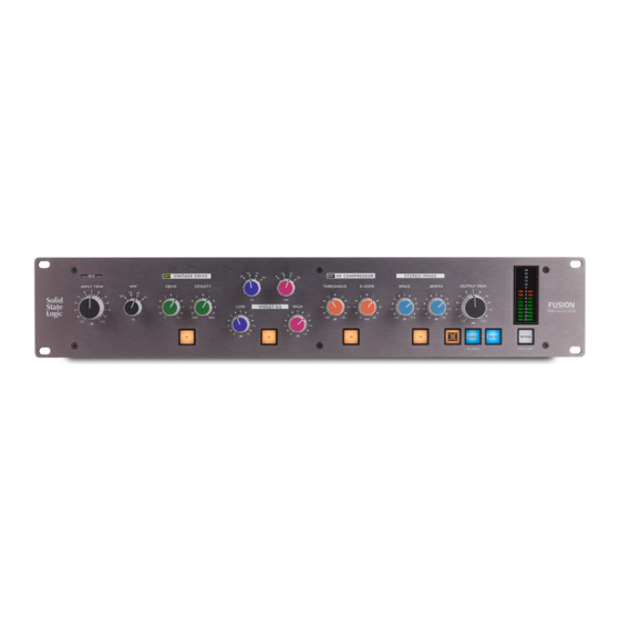
Introduction Fusion is an all-analogue stereo outboard processor created for the hybrid studio. Fusion introduces five completely new analogue colouration tools designed to bring the perfect combination of added tonal character, clarity and depth to your mix bus or stereo stems with the detail, warmth and finesse that only real analogue circuits can provide. -
Page 7: Unpacking
Rack Mounting, Heat & Ventilation Fusion is a 2U, 19” rackmount piece of equipment designed to sit in the racking of a producer’s desk or similar. Fusion’s no compromise design is powered by a toroidal transformer and as such, the left-hand side of the unit can become warm to the touch. -
Page 8: Hardware Overview
Balanced Insert IEC Power Inlet Balanced Outputs Sends and Switch Warning! Check the fuse orientation matches your supply voltage. Warning! The left-hand side of Fusion can become warm due to the linear power supply. Take care when handling. Fusion User Guide... -
Page 9: Signal Flow Overview
Hardware Overview Signal Flow Overview A detailed Block Diagram is available in Appendix C. The diagram below gives you an overview of the signal path options Fusion provides. VINTAGE VIOLET INSERT STEREO TRANSFORMER DRIVE COMPRESSOR POINT IMAGE INSERT (Standard) VINTAGE... -
Page 10: Setup Examples
Alternative Setup Option If you do not use the hardware insert functionality in your DAW, you can use the following method to integrate Fusion into your setup: Choose a pair of analogue inputs and outputs that are not being used on your audio interface e.g. outputs 3 & 4 and inputs 1 &... -
Page 11: Connecting Fusion To An Analogue Desk / Summing Mixer
Connecting Fusion to an Analogue Desk / Summing Mixer Fusion is the ideal analogue processor to complement your analogue summing system. The example below shows how to connect Fusion and an SSL Bus Compressor to your analogue desk or summing mixer. -
Page 12: Start Me Up
Fusion. Remember, a number of Fusion’s circuits are level-dependent and this will affect the sound you get. Depending on how loud or quiet your mix already is, you may need to start by adjusting the INPUT TRIM in order to achieve the best possible gain-staging. -
Page 13: Tutorial
Left and Right Overload LEDs light red if the signal at Fusion’s input exceeds +27dBu. Input Trim The INPUT TRIM provides ±12dB gain at the input stage of Fusion. This pot is indented at the 12 o’clock position. You should use this control to achieve the best gain-staging through Fusion. Try starting with the pot at the indented 0 dB position if you are at the beginning of a the mixing process. -
Page 14: The 5 Colour Circuits
The 5 Colour Circuits The descriptions that follow cover each of Fusion’s 5 colouration circuits. Each circuit has an associated IN switch which allows you to switch that particular circuit in or out. When a circuit is on it turns orange. When bypassed, the switch is backlit a soft white colour. - Page 15 Example of additional harmonics generated using a 1kHz tone. ('High' Density) VINTAGE DRIVE bypassed. VINTAGE DRIVE engaged. Example of the saturated compression effect introduced by medium to higher Density settings. Right-hand readout shows Fusion increase the RMS level, with same Maximum Peak. Fusion User Guide...
-
Page 16: Violet Eq
Maximum Gain plots of Violet EQ - 30 Hz, 50 Hz, 70 Hz and 90 Hz. Maximum Gain plots of Violet EQ - 8 kHz, 12 kHz, 16 kHz and 20 kHz. Fusion User Guide... -
Page 17: Hf Compressor (High Frequency Compressor)
Stereo Image The STEREO IMAGE circuit allows for true mid-side processing within Fusion. Mid-Side is a technique commonly used in mastering that separates a stereo signal into 2 channels - one for the sounds in the centre (mid) of a stereo image and the other for the sounds on the edges of the stereo image (side). -
Page 18: Transformer
‘weight’ to the sound. It is worth noting that the drive of the transformer circuit is self-contained, so there is no advantage in driving the Input stage of Fusion to achieve more level through the transformer. -
Page 19: Insert (Standard Mode)
The BYPASS switch allows you to bypass all of Fusion’s processing blocks. If the BYPASS switch is red, then you are in standard BYPASS mode. Use this to compare the sound of the mix with/without Fusion in one easy action. It dimly lights white if you are not in bypass. -
Page 20: Master Meter
FRONT PANEL SWITCHES The switches used in Fusion are solid state switches that trigger a single relay for audible feedback. The benefit of this approach is that it allows for the front panel switches to be repurposed for additional functions, such as settings and secondary switch modes (M/S mode on the Insert Switch for example). -
Page 21: Settings Mode & Factory Reset
Settings Mode & Factory Reset Settings Mode & Factory Reset This section will detail how to enter Fusion's Settings Mode and the functionality that can be changed. It also details how to reset Fusion back to a factory default state. -
Page 22: Factory Reset
Settings Mode & Factory Reset Factory Reset To reset Fusion to factory settings, switch the unit on then hold down the VINTAGE DRIVE IN and BYPASS switches during the startup LED sequence. VINTAGE DRIVE Factory Reset allows reset of any stored settings (Brightness, Relay feedback, BYPASS and INSERT configurations) to the factory default. -
Page 23: Troubleshooting & Faq's
Frequently Asked Questions can be found on the Solid State Logic Website at: http://www.solidstatelogic.com/support/fusion If you require technical support for Fusion or other SSL Products, click on the Ask a Question link on the support page to open a support ticket and an SSL Product Support Engineer will be in contact. -
Page 24: Soak Mode
For all warranty inquiries or claims please address your claim to the dealer that you purchased the product from – or to Solid State Logic if the purchase was directly from Solid State Logic –... -
Page 25: Appendix A - Physical Specification
Power 50 Watts maximum, 40 Watts typical Unboxed Weight 5.86kg / 12.9lbs Boxed Size 550mm x 470mm x 225mm (21.7" x 18.5" x 8.9") Boxed Weight 9.6kg / 21.2lbs Note: All physical specification values are approximate. Connectors Fusion User Guide... -
Page 26: Appendix B - Analogue Specification
> 2% typical CMRR 20Hz > 78dB, 85dB typical 1kHz > 78dB, 88dB typical Noise Analyser filters/BW: 22Hz to 20kHz (AES17). All circuits off < -86dBu, -91dBu typical Bypass -94dBu typical Vintage Drive, mid Drive, mid Density -75dBu typical Fusion User Guide... - Page 27 +24dBu into one channel, analyzer on the other channel (generator connected but not active). All circuits off / bypass 1 kHz < -110dB, -115dB typical 20Hz -110dB typical Stereo Matching All circuits off / Bypass < 0.01dB Vintage Drive on < 0.25dB typical Fusion User Guide...
-
Page 28: Appendix C - System Block Diagram
Appendix C Appendix C - System Block Diagram Fusion User Guide... -
Page 29: Appendix D - Safety Notices
The cord should bear the approval mark of the country in which it is to be used. Connect only to an AC power source that contains a protective earthing (PE) conductor. Only connect units to single phase supplies with the neutral conductor at earth potential. Fusion User Guide... -
Page 30: Ce Certification
When servicing disconnect all power sources before removing any panels. CE Certification Fusion is CE compliant. Note that any cables supplied with SSL equipment may be fitted with ferrite rings at each end. This is to comply with the current regulations and these ferrites should not be removed. -
Page 31: Electromagnetic Compatibility
WARNING: Operation of this equipment in a residential environment could cause radio interference. Environmental Temperature: Operating: +1 to 30 degrees Celsius. Storage: -20 to 50 degrees Celsius. Fusion User Guide... -
Page 32: Appendix E - Selecting Mains Voltage
Appendix E - Selecting Mains Voltage Fusion has a linear power supply and therefore needs to be manually switched to operate with either a 230V or 115V power suppy. The AC mains fuse is located on the rear panel next to the AC 115V mains connector. -
Page 33: Changing The Fuse From 230V To 115V
Re-orientate the fuse cartridge 180 degrees and reposition it so that the alternate operating voltage value is displayed through the slot in the fastening. Re-seal the fastening, reconnect the IEC power cable, and switch the unit on. Fusion User Guide... -
Page 34: Appendix F - Recall Sheet
Appendix F Appendix F - Recall Sheet Fusion User Guide... - Page 35 Fusion. This is SSL.
Need help?
Do you have a question about the Fusion and is the answer not in the manual?
Questions and answers