
Related Manuals for Lifetime 90136


Summary of Contents for Lifetime 90136
- Page 1 MODEL N° 90136 COMPLETE BASKETBALL SYSTEM OWNER’S MANUAL OWNER’S MANUAL Keep this Product ID Number and use when contacting Customer Service:...
- Page 2 Maintaining your privacy is our long-standing policy at Lifetime. And you can rest as- sured that Lifetime will not sell or provide your personal data to other third parties, or allow them to use your personal data for their own purposes.
- Page 3 SAFETY INSTRUCTIONS DAMAGE AND WILL VOID WARRANTY. To ensure safety, do not attempt to assemble this product without reading and materials for parts and/or additional instruction material. identify and inventory all parts and hardware using the parts and hardware lists and identifiers in this document.
- Page 4 TOOLS AND PARTS REQUIRED FOR THIS ASSEMBLY 3/16” Allen Wrench 1/2” Wrench (1, included) *Two adults required to complete assembly* Only adults should set up the product. Do not allow children in the setup area until assembly is complete.
- Page 5 ASSEMBLY GUIDES Refer to the following areas throughout the instructions to assist in the assembly process: This area is located at the top, TOOLS AND HARDWARE REQUIRED FOR THIS PAGE left-hand corner of the page and indicates which tools and hardware are needed to complete the assembly steps on a page.
- Page 6 INSTALLATION & GROUND PREPARATION INSTRUCTIONS Place the equipment on a level, well-drained ground, not less than 6 ft (1.8 m) from any structure or obstruction such as a fence, garage, or house. Provide enough room so that children can use the equipment safely. For example, for struc- tures with multiple play activities, a slide should not exit in front of a swing.
- Page 7 OPERATING INSTRUCTIONS Observing the following instructions and warnings reduces the likelihood of serious or fatal injury: The maximum number of occupants that may safely use the entire playset is six with a maximum weight of 600 pounds (272 kg). On-site adult supervision should be provided for children of all ages. Instruct children not to use the equipment in a manner other than intended.
- Page 8 The U.S. Consumer Product Safety Commission materials if they are installed and maintained at (CPSC) estimates that about 100,000 playground depths of 6, 9, and 12 inches. However, it should be equipment related injuries resulting from falls to the recognized that all injuries due to falls cannot be ground surface are treated annually in U.S.
- Page 9 PARTS LIST Item Description Handhold HARDWARE LIST Item Description Geodome Assembly Hardware Bag 5/16” Nut...
- Page 10 PARTS IDENTIFIER Parts shown at 5% of Actual Size Handhold HARDWARE IDENTIFIER GEODOME ASSEMBLY HARDWARE (CPA) Hardware shown at Actual Size 5/16” Standard Nut...
- Page 11 TOOLS AND HARDWARE REQUIRED FOR THIS PAGE 3/16” Slide a Washer (ARL) over a 5/16” x t (ASI) through the two and four Light Brown Tubes (CPD) in the order indicated by the numbers. Slide another Washer 5/16” Standard Nut (ATL). Hold the prevent movement.
- Page 12 TOOLS AND HARDWARE REQUIRED FOR THIS PAGE 3/16” 1/2” Attach a Light Brown Tube (CPD) to the bottom of the assembly completed in the previous step (Joint A). Slide a through a Washer (ARL) over the Nylock Nut (ASE) for removal later. Follow the Note: Repeat this step on all five assemblies.
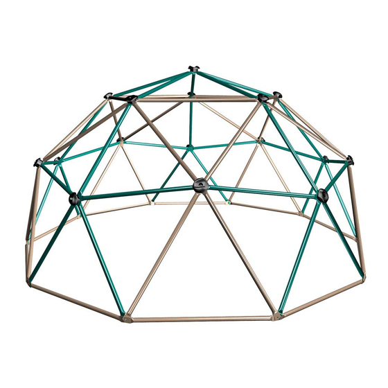
- Page 13 TOOLS AND HARDWARE REQUIRED FOR THIS PAGE 3/16” 1/2” shown. Place a Green Tube (CPC) over the Light Brown Tubes (CPD) and shown below by placing a 5/16” x Bolt (ASI) through Washer (ARL) 5/16” Standard Nut (ATL) for removal later. Note: The Geo-Dome should be stood upright to complete this step and the rest of the assembly.
- Page 14 TOOLS AND HARDWARE REQUIRED FOR THIS PAGE 3/16” 1/2” Add two additional Green Tubes (CPC) in the order indicated. Place the 5/16” x Bolt (ASI) through the Washer (ARL) then through the five 5/16” Standard Nut (ATL). Tighten completely.
- Page 15 TOOLS AND HARDWARE REQUIRED FOR THIS PAGE 3/16” NO NEW HARDWARE REQUIRED 1/2” Remove 5/16” Nylock Nut (ASE) from the bottom two Light Brown Tubes (CPD) Green Tubes (CPC) Washer (ARL) and the Note: Make sure all Bolts on the bottom go in the direction shown, with the head of the Bolt on the outside, to prevent injury.
- Page 16 TOOLS AND HARDWARE REQUIRED FOR THIS PAGE 3/16” 1/2” Add one of the assemblies completed in step 1.2, to the assembly 1.5 to attach the assemblies. Continue adding the assemblies from step 1.2 to complete the circle.
- Page 17 TOOLS AND HARDWARE REQUIRED FOR THIS PAGE 3/16” NO NEW HARDWARE REQUIRED 1/2” Remove the 5/16” Standard Nut (ATL), the Washers (ARL) and the Bolt (ASI) at Joint C and add an additional Light Brown Tube with Sticker (CPE) tighten to Joint D, repeat the same process for Joint E. in the order indicated.
- Page 18 TOOLS AND HARDWARE REQUIRED FOR THIS PAGE 3/16” 1/2” Connect the five Green Tubes (CPC) at the top by sliding a 5/16” x Bolt (ASI) through a Washer (ARL) the order shown. Secure with a Washer and 5/16” Standard Nut (ATL). Tighten completely.
- Page 19 TOOLS AND HARDWARE REQUIRED FOR THIS PAGE 3/16” 1/2” Attach Handholds (CPB) Attach the handholds by sliding a Washer (ARL) over the (ASI) It is critical that the Washer is added Washer and 5/16” Nylock Nut (ASE). Tighten completely. Handhold notch fits over the top of the Tube joint WARNING handholds are in place and secure.
- Page 20 NOTES...
- Page 21 NOTES...
- Page 22 ® ENHANCE YOUR LIFETIME PURCHASE BY ADDING ACCESSORIES OR OTHER GREAT PRODUCTS: To purchase accessories or other Lifetime Products, visit us at: www.lifetime.com Or call: 1-800-424-3865...
- Page 23 1073434 Lifetime Products, Inc PO Box 160010 • Freeport Center, Bldg. D-11 • Clearfield, UT 84016 • USA • 1-800-225-3865...
- Page 24 ALL WARRANTY CLAIMS MUST BE ACCOMPANIED BY A SALES RECEIPT. **Call or visit our Web site for Saturday hours** Please include your dated sales receipt and photographs of damaged parts. To register the product, visit our Web site at www.lifetime.com www.lifetime.com *Warranty is only valid in the United States.
Need help?
Do you have a question about the 90136 and is the answer not in the manual?
Questions and answers