Advertisement
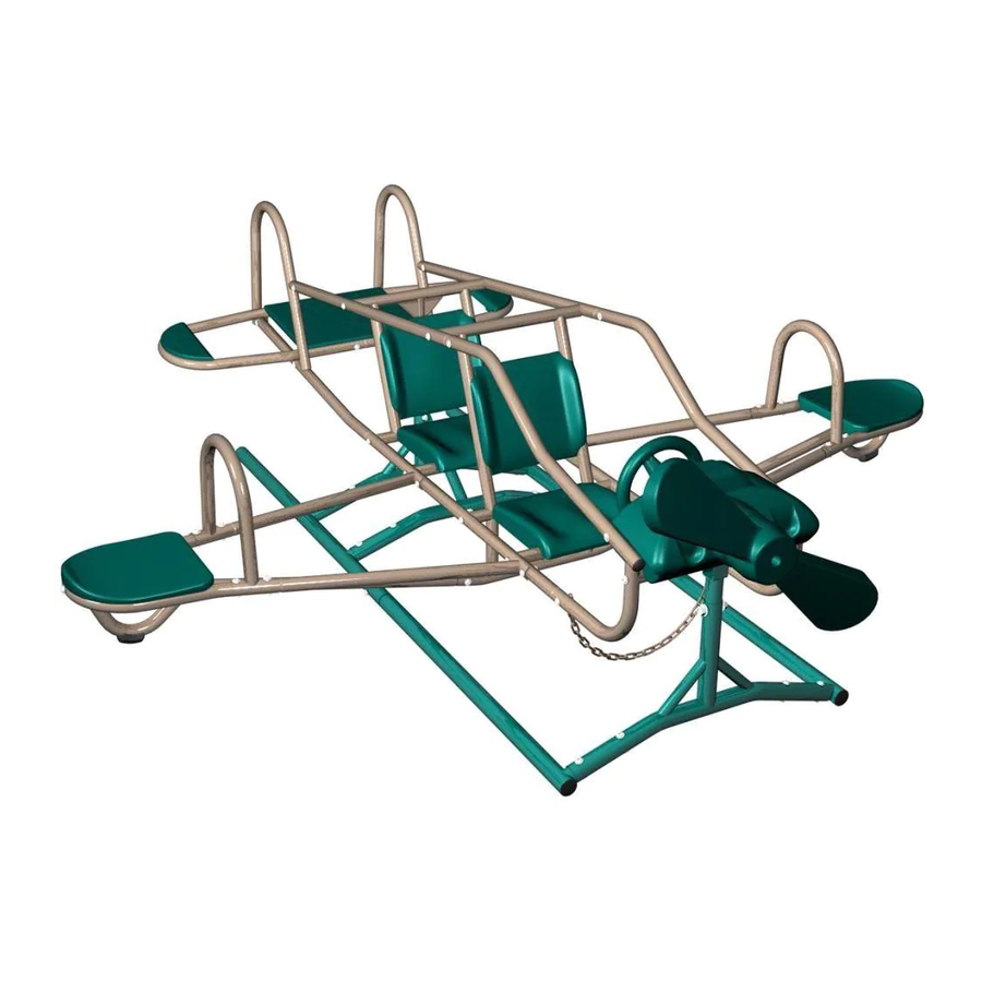
ACE FLYER
TEETER-TOTTER
MODEL #60091
MODEL 90135
BEFORE ASSEMBLY:
• Prepare a level surface with the proper Safety Zone
(see page 12).
• 3 people recommended for setup
Save this instruction in the event that the manufacturer has
to be contacted for replacement parts.
TOOLS REQUIRED
1/2 in/po (≈13 mm)
(1)
3/16 in/po (≈5 mm)
(2)
3/4 in/po (≈19 mm)
(2)
(1)
ASSEMBLY INSTRUCTIONS
(1)
(1)
(2)
TABLE OF CONTENTS
Icon Legend...............................4
Warnings & Notices.....................5
Safety Information.....................6
Safe Play Area..........................12
Base Assembly..........................13
Fuselage Assembly....................17
Parts Identifi er..........................i-iv
Wing Assembly.........................27
Cockpit Assembly......................33
Maintenance..........................36
Warning Sticker.........................39
Registration..........................40
Warranty...........................41
Advertisement
Table of Contents

Related Manuals for Lifetime 90135


Summary of Contents for Lifetime 90135
-
Page 1: Table Of Contents
ASSEMBLY INSTRUCTIONS ACE FLYER TEETER-TOTTER MODEL #60091 MODEL 90135 BEFORE ASSEMBLY: • Prepare a level surface with the proper Safety Zone (see page 12). • 3 people recommended for setup Save this instruction in the event that the manufacturer has to be contacted for replacement parts. -
Page 2: Icon Legend
ICON LEGEND Indicates special heed should be taken when reading. Indicates the parts to be used for a section. Indicates no parts required for a specifi c section. Indicates the hardware to be used for a section. Indicates no hardware required for a specifi c page. Indicates the tools to be used for a section. -
Page 3: Warnings & Notices
WARNINGS & NOTICES SAFETY INSTRUCTIONS FAILURE TO FOLLOW THESE WARNINGS MAY RESULT IN SERIOUS INJURY OR PROPERTY DAMAGE AND WILL VOID WARRANTY. Owner must ensure that all players know and follow these rules for safe operation of the system. To ensure safety, do not attempt to assemble this product without following the instructions carefully. Check entire box and inside all packing material for parts and/or additional instruction material. -
Page 4: Safety Information
**IMPORTANT SAFETY INFORMATION** PLEASE READ BEFORE BEGINNING ASSEMBLY: INSTALLATION & GROUND PREPARATION INSTRUCTIONS • Place the equipment on a level, well-drained ground, not less than 6.6 ft (2.0 m) from any structure or obstruction such as a fence, garage, house, overhanging branches, laundry lines, or electrical wires. •... - Page 5 CONSUMER INFORMATION SHEET FOR PLAYGROUND SURFACING MATERIALS* Select Protective Surfacing—One of the most important things you can on play equipment support posts. That way you can easily see when to do to reduce the likelihood of serious head injuries is to install shock- replenish and/or redistribute the surfacing.
-
Page 6: Safe Play Area
SAFE PLAY AREA SAFETY ZONE — Place the equipment no less than 6.6 ft. (2 m) from any structure or obstruction such as a fence, garage, house, overhanging branches, laundry lines, or electrical wires. The impact surfacing needs to cover the entire recommended play area. Refer to the example below. 6.6' (2m) 6.6 ft (2m) 6.6' (2m) -
Page 7: Base Assembly
BASE ASSEMBLY HARDWARE REQUIRED Hardware Bag DXY (x14) ASE (x1) ATE (x4) ATB (x14) CVZ (x17) ATD (x2) ARU (x1) ARN (x1) ATC (x2) ASN (x2) PARTS REQUIRED Metal Part CPN (x1) CPL (x1) CPM (x1) CPP (x2) CPO (x1) CPQ (x2) CPR (x2) •... - Page 8 SECTION 1 (CONTINUED) TOOLS AND HARDWARE REQUIRED 3/16 in/po (≈5 mm) DXY (x12) ATB (x12) CVZ (x12) • Connect the two Front Skids (CPP) to the Front Cross Brace (CPL) with the hardware shown. • Connect the two Rear Skids (CPQ) to the Rear Cross Brace (CPM) and the Middle Cross Brace (CPN). Secure with the hardware shown.
- Page 9 SECTION 1 (CONTINUED) TOOLS AND HARDWARE REQUIRED 3/16 in/po (≈5 mm) 1/2 in/po (≈13 mm) ARN (x1) CVZ (x3) ARU (x1) ASE (x1) • Make sure all parts are oriented correctly before continuing. This bracket should be facing the direction shown. This hole should be in the location shown.
- Page 10 SECTION 1 (CONTINUED) TOOLS AND HARDWARE REQUIRED 3/16 in/po (≈5 mm) ATC (x2) CVZ (x2) 3/4 in/po (≈19 mm) ATE (x4) DXY (x2) ATD (x2) ATB (x2) • Connect the two assemblies completed in steps 1.1 - 1.4. Secure with the hardware shown. •...
-
Page 11: Fuselage Assembly
FUSELAGE ASSEMBLY HARDWARE REQUIRED Hardware Bag Hardware Bag ATG (x16) DXX (x6) ASB (x14) ATI (x2) ATH (x2) AWS (x14) CVZ (x24) ATB (x6) ASE (x2) PARTS REQUIRED Metal Part CPS (x2) CPT (x2) CPU (x2) CQA (x2) CPV (x2) CQB (x1) - Page 12 FUSELAGE ASSEMBLY PARTS REQUIRED Metal Parts CPW (x1) CPX (x1) CQL (x1) CPZ (x2) CPY (x2) TOOLS REQUIRED 1/2 in/po (≈13 mm) 3/16 in/po (≈5 mm)
- Page 13 SECTION 2 (CONTINUED) TOOLS AND HARDWARE REQUIRED 3/16 in/po (≈5 mm) ATG (x8) • Connect a Cockpit Backrest (CPY) to the Back Seat Back Support (CPX) and Front Seat Back Support (CPW). Secure using the hardware shown. Do not overtighten. Make sure the seats are placed so the sticker is right side up. •...
- Page 14 SECTION 2 (CONTINUED) TOOLS AND HARDWARE REQUIRED 3/16 in/po (≈5 mm) DXX (x4) ATB (x4) CVZ (x4) • Secure the Fuselage assembled in Sec 2.2 with the hardware shown. Make sure to insert the T-Nuts (ATB) so they face the opposite side of the assembly as the dimpled holes in the tubes. Repeat this step with the hardware in the reverse direction to complete the other Fuselage frame.
- Page 15 SECTION 2 (CONTINUED) TOOLS AND HARDWARE REQUIRED 3/16 in/po (≈5 mm) AWS (x8) ASB (x8) CVZ (x8) • Place the assembled Back Seat Back Support (CPX) in between the two fuselage frames. Place the Coped Caps (AWS) in the location pictured and line up the holes in the Back Seat Back Support with the holes in the fuselage frame. •...
- Page 16 SECTION 2 (CONTINUED) TOOLS AND HARDWARE REQUIRED AWS (x2) 3/16 in/po (≈5 mm) ASB (x2) ATG (x4) CVZ (x2) • Position the Cockpit Seat Support (CQA) in the location shown, with a Coped Cap (AWS) on each end. Place the hardware through the Fuselage frames and into the seat support and fi...
-
Page 17: Parts Identifi Er
PARTS IDENTIFIER Metal Parts CPN (x1) CPL (x1) CPM (x1) CPP (x2) CPO (x1) CPQ (x2) CPR (x2) • Part CPU is packaged inside part CPQ. Part CPV is packaged inside part CPP. Please remove these parts before assembly. CPS (x2) CPT (x2) CPU (x2) CQA (x2) - Page 18 PARTS IDENTIFIER Metal Parts CPW (x1) CPX (x1) CQL (x1) CPZ (x2) CPY (x2) CQC (x2) CQD (x4) CQE (x2) CQF (x2) CQG (x1)
- Page 19 PARTS IDENTIFIER Plastic Parts CQH (x1) CQK (x1) CQJ (x1) CQI (x1) HARDWARE REQUIRED ACCESSOIRES REQUIS...
- Page 20 SECTION 2 (CONTINUED) TOOLS AND HARDWARE REQUIRED AWS (x2) 3/16 in/po (≈5 mm) ASB (x2) ATG (x4) CVZ (x2) • Position the Cockpit Seat Support (CQA) in the location shown, with Coped Caps (AWS) on each end of the tube. Place the hardware through the fuselage frames and into the seat support and fi...
- Page 21 SECTION 2 (CONTINUED) TOOLS AND HARDWARE REQUIRED AWS (x2) ASB (x2) CVZ (x2) 2.11 • Place a Coped Cap (AWS) at each end of the Front Horizontal Pivot (CQB). Position the Front Horizontal Pivot with the dimpled hole facing outward at the front of the fuselage assembly as shown. Secure with the hardware shown. •...
- Page 22 SECTION 2 (CONTINUED) TOOLS AND HARDWARE REQUIRED 3/16 in/po (≈5 mm) 1/2 in/po (≈13 mm) ATI (x2) ATH (x2) ASE (x2) CVZ (x4) 2.12 • Using two people, lift the Fuselage assembly and position it on the Skid and Cross Brace assembly. Line up the holes in the Front Horizontal Pivot (CQB) and the Rear Seat Back Support (CPX) with the holes in the Adjustment Stands (CPR).
- Page 23 SECTION 2 (CONTINUED) TOOLS AND HARDWARE REQUIRED 3/16 in/po (≈5 mm) ATB (x2) DXX (x2) CVZ (x2) 2.13 • Secure the Chain Foot Rest (CQL) to the Fuselage with the hardware shown by positioning the chain links over the holes in the fuselage.
-
Page 24: Wing Assembly
WING ASSEMBLY HARDWARE REQUIRED Hardware Bag ASB (x2) DXX (x18) ATB (x18) CVZ (x20) PARTS REQUIRED Metal Part CQC (x2) CQD (x4) CQE (x2) CQF (x2) CQG (x1) TOOLS REQUIRED 3/16 in/po (≈5 mm) - Page 25 SECTION 3 (CONTINUED) TOOLS AND HARDWARE REQUIRED 3/16 in/po (≈5 mm) ATB (x9) DXX (x9) CVZ (x9) • Slide the Wing Pieces (CQD) into the Wing Tip Seat (CQF) as shown. Place the Wing Handle (CQE) onto the Wing Tip Seat and secure with the hardware shown.
- Page 26 SECTION 3 (CONTINUED) TOOLS AND HARDWARE REQUIRED 3/16 in/po (≈5 mm) DXX (x2) ATB (x2) CVZ (x2) • Remove the Bolts (ASB) and Washers (CVZ) from the seat support (on the side of the Fuselage shown) that were placed in Sec 2.7 and 2.9. ASB CVZ •...
- Page 27 SECTION 3 (CONTINUED) TOOLS AND HARDWARE REQUIRED 3/16 in/po (≈5 mm) ASB (x1) DXX (x1) ATB (x1) CVZ (x2) • Position the Wing Assembly into the notch at the end of the Wing Support Brace (CQC) and secure the Wing Assembly to the Wing Support Brace with the hardware shown.
- Page 28 SECTION 3 (CONTINUED) TOOLS AND HARDWARE REQUIRED 3/16 in/po (≈5 mm) DXX (x2) ATB (x2) CVZ (x2) • Remove the Bolts (ASB) and Washers (CVZ) from the seat support (on the side of the Fuselage shown) that were placed in Sec 2.7 and 2.9. •...
- Page 29 SECTION 3 (CONTINUED) TOOLS AND HARDWARE REQUIRED 3/16 in/po (≈5 mm) ASB (x1) DXX (x4) ATB (x4) CVZ (x5) • Position the Wing Assembly into the notch at the end of the Wing Support Brace (CQC), and secure the Wing to the Wing Support Brace with the hardware shown.
-
Page 30: Cockpit Assembly
COCKPIT ASSEMBLY HARDWARE REQUIRED Hardware Bag / Sac d’accessoires Bolsa de accesorios ATJ (x4) ARX (x2) ATK (x2) CVZ (x6) PARTS REQUIRED Metal Part CQH (x1) CQK (x1) CQJ (x1) CQI (x1) TOOLS REQUIRED 3/16 in/po (≈5 mm) - Page 31 SECTION 4 (CONTINUED) TOOLS AND HARDWARE REQUIRED 3/16 in/po (≈5 mm) ATJ (x4) ARX (x1) CVZ (x5) ATK (x1) • Place the Nose and Dashboard Assembly (CQH) on the front of the fuselage and Position it over the Front Horizontal Pivot (CQB).
- Page 32 SECTION 4 (CONTINUED) TOOLS AND HARDWARE REQUIRED 3/16 in/po (≈5 mm) ARX (x1) ATK (x1) CVZ (x1) • Slide the Steering Tube (CQI) through the front of the Nose all the way to the Dashboard side of the assembly. • Place the Formed Washer (ATK) at the end of the Steering Tube, and align the notch on the nub in the steering wheel as shown in Sec 4.2.
-
Page 33: Maintenance
MAINTENANCE INSTRUCTIONS If routine checks and maintenance procedures are not done, the equipment could overturn and/or become a hazard. At the beginning of each play season: • Tighten all hardware. • Lubricate all metallic moving parts. • Check all protective coverings on bolts, pipes, edges and corners. Replace if they are loose, cracked or missing. •... -
Page 34: Warranty
2. This warranty is nontransferable and is expressly limited to the repair or replacement of defective playground equipment. If the equipment is defective within the terms of this warranty, Lifetime Products, Inc. will repair or replace defective parts at no cost to the purchaser.
Need help?
Do you have a question about the 90135 and is the answer not in the manual?
Questions and answers