Advertisement
Electronic copies of the most current TSM issue can be found on the Viking Pump website at www.vikingpump.com
SERIES SG-04, SG-05 & SG-07 SPUR GEAR PUMPS
CONTENTS
Installation ...................................................... 1
Mounting ......................................................... 2
Start Up .......................................................... 3
Troubleshooting .............................................. 6
Miscellaneous ................................................. 8
Do's and Don'ts ............................................. 9
Warranty ....................................................... 10
INSTALLATION
General
The following items must be considered prior to pump installation:
1.
Location - locate the pump as close as possible to the liquid supply. If possible locate the
pump below the liquid supply. Viking pumps are self-priming; but the better the suction
conditions, the better the pump will perform.
2.
Accessibility - the pump must be accessible for inspection, maintenance and repair.
3.
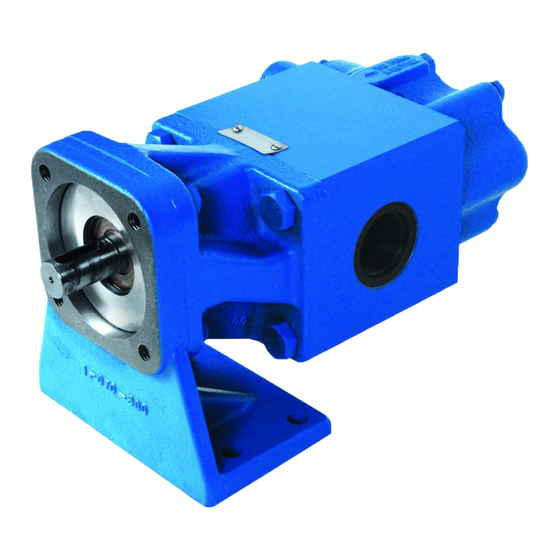
Suction/Discharge - SG Series pumps are designed for clockwise rotation as standard
(viewed from end of shaft). Refer to Figure 1.
4.
Pressure Relief Valve - the SG Series is a positive displacement pump and requires some
form of over pressure protection. Without pressure protection, if the discharge line is
blocked or becomes closed, pressure will build up until the motor stalls, drive equipment
fails, a pump part breaks, or the piping and/or other equipment in the system bursts.
To prevent the possibility of any one or more of the above from occurring, the use of a
pressure relief valve is recommended.
5.
Storage - drain the pump and apply a light coat of non-detergent SAE 30 weight oil to all
internal pump parts. Apply grease to the pump shaft extension. Viking suggests rotating
the pump shaft by hand one complete revolution every 30 days to circulate the oil.
VIKING PUMP, INC. • A Unit of IDEX Corporation • Cedar Falls, IA 50613 USA
TECHNICAL SERVICE
MANUAL
INSTALLATION, START UP, TROUBLESHOOTING,
PREVENTIVE MAINTENANCE, DO'S & DON'TS
SECTION TSM 340
PAGE
ISSUE
S
S
FIGURE 1
1 OF 10
H
D
D
Advertisement
Table of Contents

Related Manuals for Viking pump SG-04 SERIES


Summary of Contents for Viking pump SG-04 SERIES
-
Page 1: Table Of Contents
Electronic copies of the most current TSM issue can be found on the Viking Pump website at www.vikingpump.com SECTION TSM 340 TECHNICAL SERVICE PAGE 1 OF 10 MANUAL ISSUE INSTALLATION, START UP, TROUBLESHOOTING, PREVENTIVE MAINTENANCE, DO’S & DON’TS SERIES SG-04, SG-05 & SG-07 SPUR GEAR PUMPS CONTENTS Installation ............ -
Page 2: Mounting
MOUNTING Surfaces to which the pump mounts must be clean and flat. Use SAE Grade 5 or better capscrews to mount pump. The 4 mounting capscrews for the SG-04 and SG-05 pumps must have a minimum of ½ inch thread engagement, and must be torqued evenly to 12-15 ft-lbs. The 2 mounting capscrews for the SG-07 pumps must have a minimum of ½... -
Page 3: Start Up
Be sure the inside of the pipe is clean before installing. When approaching an obstacle to the suction line, go around instead of over it. Going over an obstacle can create an air pocket. Where practical, slope the piping so no air or liquid pockets will be formed. - Page 4 TYPICAL SG-04/SG-05 EXPLODED VIEW TYPICAL SG-07 EXPLODED VIEW ITEM DESCRIPTION ITEM DESCRIPTION Bracket, lipseal & bearing section Relief valve kit Match ground casing & (2) gears, driver & Lipseal driven shafts Separation plate & bearing assy. O-ring Head and alignment sleeve assy. Assembly capscrews SECTION TSM ISSUE...
- Page 5 10. The above checklist is a general guideline to be used prior to starting the pump. Since Viking Pump cannot foresee every application for our product and possible system design, the final responsibility is with the user. The pump must be utilized within the catalog specifications and the pump system must be designed to provide safe working conditions.
-
Page 6: Troubleshooting
TROUBLESHOOTING A Viking pump that is properly installed and maintained will give long satisfactory performance. If trouble does develop, one of the first steps toward finding the difficulty is to install a vacuum gauge in the suction line and a pressure gauge in the discharge line. Readings on these gauges often give a clue on where to start looking for trouble. - Page 7 Fluttery, jumping or erratic reading would indicate: The liquid is vaporizing. Liquid is coming in to the pump in slugs, possibly an air leak or insufficient liquid above the end of the suction pipe. Vibration from cavitation, misalignment, or damaged parts. Pressure Gauge - Discharge Port High reading would indicate: High viscosity and small diameter and/or lengthy discharge line.
-
Page 8: Miscellaneous
MISCELLANEOUS Pump does not pump: The pump has lost its prime from air leak or low level in tank. The suction lift is too high. Rotating in the wrong direction. The motor does not come up to speed. The strainer is clogged. The bypass valve is open, pressure relief valve set too low or pressure relief valve poppet stuck open. -
Page 9: Do's And Don'ts
DO’S AND DON’TS Do’s and Don’ts for installation, operation and maintenance of Viking pumps to assure safe, long, trouble free operation. Installation: DO install the pump as close to supply tank as possible. DO leave working space around the pumping unit. DO use large, short and straight suction port. -
Page 10: Warranty
OR PLACED ON NOTICE OF THE POSSIBILITY OF SUCH DAMAGES AND NOTWITHSTANDING THE FAILURE OF ANY ESSENTIAL PURPOSE OF ANY PRODUCT. VIKING PUMP, INC. • A Unit of IDEX Corporation • Cedar Falls, IA 50613 USA © 12/2016 Viking Pump Inc. All rights reserved...
Need help?
Do you have a question about the SG-04 SERIES and is the answer not in the manual?
Questions and answers