Table of Contents
Advertisement
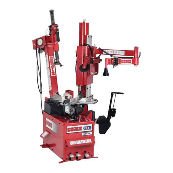
GTS50/60/70 and GTS90
Rim Clamp
For servicing single piece automotive and most tubeless
light truck tire/wheel assemblies.
Any other type, including tube type and agricultural, require special handling.
Tires identifi ed as truck tires need to adhere to OSHA standard 1910.177.
See
RIM Safety
Operating
Instructions
on page 4.
1601 J. P . Hennessy Drive, LaVergne, TN USA 37086
HENNESSY INDUSTRIES INC. Manufacturer of AMMCO
Tire Changers
®
Operation Instructions
page vi.
Maintenance Instructions
READ these instructions before placing unit in
service. KEEP these and other materials delivered
with the unit in a binder near the machine for ease
of reference by supervisors and operators.
615/641-7533
800/688/6359
, COATS
and BADA
®
®
Safety Instructions
Set-up Instructions
www.coatsgarage.com
Automotive Service Equipment and Tools.
®
Manual Part No.:
85610001 06
Revision:
09/17
Advertisement
Table of Contents

Related Manuals for Coats gts series


Summary of Contents for Coats gts series
- Page 1 1601 J. P . Hennessy Drive, LaVergne, TN USA 37086 615/641-7533 800/688/6359 www.coatsgarage.com Manual Part No.: 85610001 06 HENNESSY INDUSTRIES INC. Manufacturer of AMMCO , COATS and BADA Automotive Service Equipment and Tools. Revision: 09/17 ® ® ®...
- Page 2 NOTICE Read entire manual before assembling, installing, operating, or servicing this equipment. ii • Important: Always read and follow operating instructions.
-
Page 3: Table Of Contents
Table of Contents Tire Specifications Diagram ..........iv Safety Instructions ..............v Owner’s Responsibility............v Operator Protective Equipment .........v Definitions of Hazard Levels ..........v Safety Notices and Decals ..........vi Remember R.I.M.............. vi Setup Instructions ...............1 Location ................1 Workspace Requirements ..........1 Air Source ................1 Electrical Source ..............1 Floor Mounting ..............1 Principal Operating Parts ............2... -
Page 4: Tire Specifications Diagram
Tire Specifi cations Diagram Radial Rim diameter code Ratio of height to Load index & width (aspect ratio) speed symbol Nominal width of tire in millimeters U.S. DOT tire identification number Passenger car tire Severe snow conditions Max. Tire ply permissible composition inflation... -
Page 5: Safety Instructions
Safety Instructions Definitions of Hazard Levels Identify the hazard levels used in this manual with the Owner’s Responsibility following definitions and signal words: To maintain machine and user safety, the responsibility DANGER of the owner is to read and follow these instructions: Watch for this symbol: •... -
Page 6: Safety Notices And Decals
Coats distributors nationwide. www.rma.org Tire Guides, Inc. The Tire Information Center 1101-6 South Rogers Circle Boca Raton, FL 33487-2795 (561) 997-9229 www.tireguides.com For more details, contact your Coats distributor or e-mail us. vi • Important: Always read and follow operating instructions. -
Page 7: Setup Instructions
Setup Instructions Air Source The all-air models require a 14 to 15 CFM air source at 150 PSI. The air/electric models require a 5 CFM air source at 150 PSI. The operating pressure for all models is 120 PSI at the machine. Proper unit installation is necessary for safe The unit is furnished with a 1/4-inch pipe thread male use and efficient operation. -
Page 8: Principal Operating Parts
Replace any damaged or missing safety decals. They are available from COATS, (800) Inflation Pedal — Three-position pedal that registers 688-6359. tire pressure, allows inflation of tires through air hose and clip-on chuck or allows air flow through bead sealing Tilt Tower —... - Page 9 Slide Locking Valve — Locks and unlocks hori- Tire Bumper Guards — Provides protective sur- zontal/vertical slide and sets correct vertical/horizontal face when bead loosening tires. position to maintain Duckhead mount/demount tool to ® Bead Loosener Shoe — Pivoting shoe for loosen- wheel clearance.
- Page 10 GTS-90 Robotic Arm Control Valve — Controls vertical movement of robotic arm cylinder. Robo-Arm® — Provides extra leverage for runflat and low profile tires. Leverless Bead Lifter Tool — Used to hook under tire bead lip for top bead removal when demounting tire from wheel.
-
Page 11: Operating Instructions
Operating Instructions This unit must be properly operated and properly maintained to help avoid accidents that could injure the operator or bystanders, or damage the unit. This section of the Operating Instructions manual review basic operations and use of controls. These instructions should be reviewed with all employees before they are allowed to work with the machine. - Page 12 5. Determine the mounting side of the wheel. The mounting side is the narrow side of the drop center. See figure 2 for more information on the drop center. Note: The wheel clamps can be positioned in one of two different ranges: •...
- Page 13 8. Take time to experiment with the Duckhead ® mount/demount tool locking system (figure 8). At times during the mounting and demount- ing procedure, the bead lifting tool may encounter resistance and can be thrown. Keep one hand firmly on the tool to avoid possible tool disconnect.
- Page 14 Note: If equipped, use disk-assist in upper position Note: If equipped, use disk-assist in lower position to press down on tire sidewall in front of mount/ and clear of table top rotation to aid in pushing up demount tool. It will aid in locating the bead lifting on lower bead of the tire (figure 14.
-
Page 15: Tire Mounting
Tire Mounting 1. Before any mounting, inspect tire for damage and verify size match between tire and wheel (figure 16). This information must be read and followed carefully to prevent accidents and injuries during mounting. Mounting a mismatched tire and wheel will cause an explosion before it bead seats during inflation. - Page 16 4. Place tire over wheel and move tower arm into 7. Depress table top pedal and rotate tire until the position. Position tire so that lower bead is above the top tire bead is mounted. Continue to press down on rear extension of the Duckhead mount/demount tool the tire to ensure bead stays in the rim drop center area...
-
Page 17: Inflation
Infl ation The inflation pedal, located at the rear of the left side of the machine, controls the flow of air through the Tire inflation is performed in three steps: BEAD SEAL, inflation hose, and has three positions. BEAD SEAT, and INFLATION. These steps are explained Note: The clip-on chuck on the end of the hose is a in detail on page 14. -
Page 18: Bead Sealing
Bead Sealing 1. Remove the valve core from the valve stem to allow more air flow into the tire to assist with bead seal. Use of bead sealing jets without a tire in 2. Position valve stem in front of operator and con- place can cause dirt and debris to be blown nect the inflation hose with the clip-on chuck. -
Page 19: Bead Seating
Bead Seating 1. Once tire pressure is indicated on the air gauge (inflation pedal in position 1; foot removed from pedal), continue to inject air into the tire (inflation pedal posi- tion 2) in short intervals. Check the pressure frequently. Stand back during bead seat. -
Page 20: Inflation
Inflation WARNING NEVER exceed tire manufacturer’s recom- mended air pressure. Tires can explode, especially if inflated beyond these limits. Use clip-on air chuck, keep hands, arms and entire body back from inflating tire. Avoid distraction during inflation. Check tire pressure frequently to avoid over infla- tion. -
Page 21: Stages Of Inflation On A Conventional Tire And Rim
Stages of Infl ation on a Conventional Tire and Rim Review these descriptions and diagrams carefully. Refer to them as necessary during bead sealing, bead seating, and inflation to verify that you are proceeding properly and safely. Bead Sealing Bead sealing is the process of capturing air pressure between the tire and the rim. -
Page 22: Mismatched Tires And Wheels
Mismatched Tires and Wheels Never mount and inflate mis-matched tires and wheels. Mismatched tire and wheel combinations will explode, if you attempt to force a bead seat, causing personal injury or death to operator and/or bystanders. 16 • Important: Always read and follow operating instructions. -
Page 23: Custom And Special Wheels
Custom and Special Wheels Tube Type Tires Mounting 1. Avoid pinching or forcing the tube. 2. Apply rubber lubricant to the beads of the tire. Only tire technicians with experience and 3. Mount the bottom bead. training on custom wheels should attempt to service expensive custom alloy or alu- 4. -
Page 24: Maintenance Instructions
If you need assistance, WARNING call an authorized service center or contact COATS directly, (800) 688-6359. 1. The vertical slide should be cleaned with a Before making any inspection, adjustment,... -
Page 25: Duckhead® Mount/Demount Tool Cleaning
WARNING you have no experience. If you need assistance, Keep the machine and the immediate work call an authorized service center or contact COATS area clean. Do not use compressed air to directly, (800) 688-6359. remove dirt and debris from the machine. -
Page 26: Oil Injector Maintenance
If you need assistance, WARNING call an authorized service center or contact COATS directly, (800) 688-6359. 1. The vertical slide should be cleaned with a Before making any inspection, adjustment,... - Page 27 8182373 8184736 85609716 85609717 (GTS70) 85610213 (GTS50) 85610214 (GTS60) 85610482 (GTS90) 8181285 85610079 8181967 85607835 8180237 8180237FR Replace any damaged or missing safety decals. They are available from COATS, (800) 688-6359. Important: Always read and follow operating instructions. • 21...
- Page 28 22 • Important: Always read and follow operating instructions.
-
Page 29: Decal Locations
Decal Locations 8183597 85611205 Important: Always read and follow operating instructions. • 23... - Page 30 AND OUTWARD WITH SUFFICIENT ENERGY NESSY INDUSTRIES, INC., 1601 J. P . HENNESSY TO CAUSE SERIOUS INJURY OR DEATH TO DRIVE, LAVERGNE, TENNESSEE, 37086 - (800) OPERATOR AND/OR BYSTANDERS. 688-6359. 85610001 06 09/2017 © Copyright 2014 Hennessy Industries and COATS® All Rights Reserved.
Need help?
Do you have a question about the gts series and is the answer not in the manual?
Questions and answers