Table of Contents
Advertisement
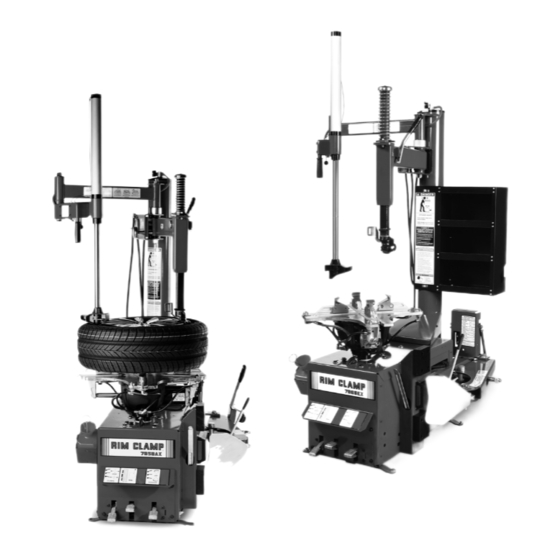
7050/7060/
7065 AX/EX
Rim Clamp
Tire Changer
For servicing single piece
automotive and most light
truck tire/wheel assemblies
See
RIM Safety page iv
¨Operating
Instructions
page 4
1601 J. P . Hennessy Drive, LaVergne, TN USA 37086-3565 615/641-7533 800/688-6359
HENNESSY INDUSTRIES INC. Manufacturer of AMMCO
®
Safety Instructions
Operating Instructions
Maintenance Instructions
Installation Instructions
READ these instructions before placing unit in
service. KEEP these and other materials delivered
with the unit in a binder near the machine for
ease of reference by supervisors and operators.
®
, COATS
®
and BADA
®
Automotive Service Equipment and Tools.
®
* 7050 & 7065 Models Shown
Manual Part No.:
8183760 05
Revision:
10/08
Advertisement
Table of Contents

Related Manuals for Coats 7050


Summary of Contents for Coats 7050
- Page 1 7050/7060/ 7065 AX/EX Rim Clamp ® Tire Changer For servicing single piece automotive and most light truck tire/wheel assemblies * 7050 & 7065 Models Shown Safety Instructions Operating Instructions Maintenance Instructions Installation Instructions RIM Safety page iv ¨Operating Instructions READ these instructions before placing unit in page 4 service.
- Page 2 ii • Important: Always read and follow the operating instructions.
-
Page 3: Operator Protective Equipment
Safety Instructions Definitions of Hazard Levels Identify the hazard levels used in this manual with the Owner’s Responsibility following definitions and signal words: To maintain machine and user safety, the responsibil- ity of the owner is to read and follow these instruc- DANGER tions: Watch for this symbol:... -
Page 4: Safety Notices And Decals
1101-6 South Rogers Circle available from Coats distributors nationwide. Boca Raton, FL 33487-2795 (561) 997-9229 www.tireguides.com For more details, contact your Coats distributor or e-mail us. iv • Important: Always read and follow the operating instructions. -
Page 5: Table Of Contents
Table of Contents Custom and Special Wheels ... . .20 Safety Instructions .....iii Alloy Wheels . -
Page 6: Principle Operating Parts
Principal Operating Parts Know Your Unit ✓ Compare this illustration with the unit before placing it Do It Now! into service. Maximum performance and safety will be Now is a good time obtained only when all persons using the unit are fully to fill out the Owner’s trained in its parts and operation. - Page 7 Bead Loosener Control Pedal — Controls opera- tion of bead loosener shoe. Available on model 7050. Table Top Pedal— Three-position pedal that controls rotation of table top (forward, off, reverse). Bead Lifting Tool — Used to lift and position tire bead correctly on duckhead ®...
-
Page 8: Operating Instructions
Operating Instructions This unit must be properly operated and properly maintained to help avoid accidents that could damage the unit and injure the operator or bystanders. This sec- tion of the Operating Instructions manual review basic operations and use of controls. These instructions should be reviewed with all employees before they are allowed to work with the machine. - Page 9 6. Place tire/wheel assembly on table top with mounting side up (figure 6). Figure 3 - Position Tire and Bead Loosener Shoe Figure 6 - Place Tire/Wheel Assembly on Table top 3. Turn the wheel around and repeat loosening pro- 7.
- Page 10 9. The mount/demount head should be in contact H. The tool clearance may change with with the rim edge. Turn the swing arm adjusting knob machine use and should be inspected often. to move the mount/demount head away from the rim Failure to maintain the proper clearance may 1/8 to 1/4 inch (figure 9).
- Page 11 13. Push the bead lifting tool down towards the wheel to lift the tire bead up and over the knob portion of the demount head. Hold the tool and bead in this position (figure 13). Figure 15 - Guide Lower Bead Over Tool Head 16.
-
Page 12: Mounting
Mounting 1. Before any mounting, inspect tire for damage and verify size match between tire and wheel (fig. 16). This information must be read and followed carefully to prevent accidents and injuries during mounting. DANGER Attempts to force a bead seat on mis- matched tires and wheels can cause the tire to violently explode, causing serious per- sonal injury or death to operator and/or... -
Page 13: Operating Instructions
4. Place tire over wheel and move swing arm into 6a. Make sure the duckhead roller mount is fully position making sure the valve stem is at the 9 o’clock engaged on the arm bracket; with no gap (figure 20a). position in front of bead lock. -
Page 14: Inflation
Inflation The inflation pedal, located at the rear of the left side of the machine, controls the flow of air through the Tire inflation is performed in three steps: BEAD inflation hose, and has three positions. SEAL, BEAD SEAT, and INFLATION. These steps are explained in detail on page 14. -
Page 15: Bead Sealing
Bead Sealing CAUTION 1. Position valve stem in front of operator and con- nect the inflation hose with the clip-on chuck. Hold tire Use of bead sealing jets without a tire in up against upper edge of the wheel. Be sure tire’s top place can cause dirt and debris to be blown bead does not cover the bottom of the valve stem (fig- into the air with enough force to injure... -
Page 16: Bead Seating
Bead Seating 1. Once tire pressure is indicated on the air gauge (inflation pedal in position 1; foot removed from pedal), DANGER continue to inject air into the tire (inflation pedal posi- tion 2) in short intervals. Check the pressure fre- quently. -
Page 17: Inflation
Inflation WARNING NEVER exceed tire manufacturer's recom- mended air pressure. Tires can explode, especially if inflated beyond these limits. Use clip-on air chuck, keep hands, arms and entire body back from inflating tire. Avoid distraction during inflation. Check tire pres- sure frequently to avoid over inflation. -
Page 18: Stages Of Inflation On A Conventional
Stages of Inflation on a Conventional Tire and Rim Review these descriptions and diagrams carefully. Refer to them as necessary during bead sealing, bead seating, and inflation to verify that you are proceeding properly and safely. Bead Sealing Bead sealing is the process of capturing air pressure between the tire and the rim. -
Page 19: Mismatched Tires And Wheels
Mismatched Tires and Wheels Never attempt to mount and inflate mis-matched tires and wheels. DANGER Mismatched tire and wheel combinations can explode, causing personal injury or death to operator and/or bystanders. 15° Even Size Tires 14.0,15.0,16.0,17 .0, etc. Note 15° bead seat Bead may seal;... -
Page 20: Performance, Custom, And Aluminum
Performance, Custom and Aluminum Wheels Ledge CAUTION Smooth Hump - Hump At Rest of Valve Only tire technicians with experience and Wheel Hole training on custom wheels should attempt to service expensive custom alloy or alu- minum wheels and high-performance low- profile tires. -
Page 21: Aluminum And Custom Wheels
Aluminim and Custom Wheels 6. Lubricate upper bead liberally. Use the bead roller tool to help push the tire bead down so bead area is Follow instructions provided for standard steel easier to reach for lubrication (figure 34). wheels, except: AC. - Page 22 8a. Place the helper foot opposite the demount 11. Demount lower bead. In most cases when head and push the bead into drop center (figure 36A). demounting performance tires, the lower bead will be less difficult. Pay close attention to sensor/transmitter location, and position it just before the demount tool when starting the lower bead demount procedure (fig- ure 39).
-
Page 23: Performance Tires And Wheels • Mounting
Performance Tires and Wheels • Mounting 4. Use RoboArm™ to push down on tire 90 degrees clockwise from Duckhead to allow bead to utilize drop 1. Lubricate both tire beads liberally. Performance center area of rim. Apply extra lubricant to mount upper tires will require more lubrication than standard pas- bead. -
Page 24: Custom And Special Wheels
Custom and Special Tube Type Tires Wheels Mounting 1. Avoid pinching or forcing the tube. CAUTION 2. Apply rubber lubricant to the beads of the tire. 3. Mount the bottom bead. Only tire technicians with experience and training on custom wheels should attempt 4. -
Page 25: Maintenance Instructions
(part number ating condition. Refer to the other materials received 107985). Contact COATS at (615) 641-7533. Check with the unit and to the service bulletins from the man- function of the pressure limiter weekly. Always rein- ufacturer for additional instructions on proper mainte- stall the lens after adjusting the gauge. -
Page 26: Duckhead (Mount/Demount Head) Adjustment
Duckhead (Mount/Demount Tool Head) Separator/Lubricator Maintenance (If Adjustment equipped) Check oil and water levels regularly, and perform To Adjust Tool Head Lift these maintenance items weekly: Loosen jam nut (ref. 1) and adjust screw (ref. 2) until lift clearance is obtained. A. -
Page 27: Pressure Limiter Maintenance
Pressure Limiter Maintenance 4. Watch the rising pressure on the tank gauge and the gauge on the machine. Machine gauge should DANGER cycle between check and inflation pressures while tank gauge climbs steadily. As tank pressure reaches 60 PSI, the pressure limiter should stop the airflow Operating a tire changer with a defective, automatically. -
Page 28: Oil Injector Maintenance (If Equipped)
Oil Injector Maintenance (If equipped) 4. Reconnect air/electric sources and cycle the clamp control pedal a few times checking for oil and air The oil injector (on units so equipped) typically require leaks. annual service. The oil level in the oil reservoir tank should be checked regularly. -
Page 29: Installation Instructions
Installation Instructions Air Source The all-air models require a 14 to 15 CFM air source at 150 PSI. The air/electric models require a 5 CFM air CAUTION source at 150 PSI. The operating pressure range for all models is between 110 PSI and 175 PSI at the Proper unit installation is necessary for safe machine. - Page 30 NOTES 26 • Important: Always read and follow the operating instructions.
- Page 31 NOTES Important: Always read and follow the operating instructions. • 27...
- Page 32 ADDITIONAL COPIES, CONTACT THE COATS ® SERIOUS INJURY OR DEATH TO OPERATOR COMPANY, 1601 J.P . HENNESSY DRIVE, AND/OR BYSTANDERS. LAVERGNE, TENNESSEE, 37086 - (800) 688-6359. 8183760 05 10/08 © Copyright 1998 Hennessy Industries and COATS All Rights Reserved Printed in USA...
Need help?
Do you have a question about the 7050 and is the answer not in the manual?
Questions and answers