
Related Manuals for KSB Omega


Summary of Contents for KSB Omega
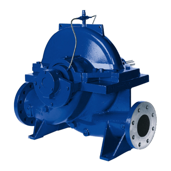
- Page 1 Axially Split Volute Casing Pump Omega / Omega V Horizontal installation type 3E Vertical installation types DB, DK, DP, DJ Installation/Operating Manual Mat. No.: 01059616...
- Page 2 Legal information/Copyright Installation/Operating Manual Omega / Omega V Original operating manual All rights reserved. The contents provided herein must neither be distributed, copied, reproduced, edited or processed for any other purpose, nor otherwise transmitted, published or made available to a third party without the manufacturer's express written consent.
-
Page 3: Table Of Contents
Scope of supply .............................22 Dimensions and weights ..........................22 Installation at Site ........................23 Safety regulations ............................23 Checks to be carried out prior to installation .....................23 Installing the pump set ..........................23 Connecting the piping ..........................30 Omega / Omega V 3 of 94... - Page 4 Explanation of faults ............................73 Related Documents ........................74 Weights of individual components ......................74 General assembly drawing with list of components ..................75 EU Declaration of conformity ....................90 Certificate of Decontamination ....................91 Index ............................92 Omega / Omega V 4 of 94...
-
Page 5: Glossary
The side of the pump which faces the motor The pipeline which is connected to the suction nozzle Hydraulic system The part of the pump in which the kinetic energy is converted into pressure energy Omega / Omega V 5 of 94... -
Page 6: General
(set) and serve as identification for all further business processes. In the event of damage, immediately contact your nearest KSB service centre to maintain the right to claim under warranty. Noise characteristics see (⇨ Section 4.6 Page 20) 1.2 Installation of partly completed machinery... - Page 7 1 General Symbol Description Step-by-step instructions Note Recommendations and important information on how to handle the product Omega / Omega V 7 of 94...
-
Page 8: Safety
▪ Do not operate the pump (set) in partially assembled condition. ▪ Only use the pump to handle the fluids described in the data sheet or product literature of the pump model or variant. Omega / Omega V 8 of 94... -
Page 9: Personnel Qualification And Training
In addition to the safety information contained in this manual and the intended use, the following safety regulations shall be complied with: ▪ Accident prevention, health and safety regulations ▪ Explosion protection regulations ▪ Safety regulations for handling hazardous substances ▪ Applicable standards, directives and laws Omega / Omega V 9 of 94... -
Page 10: Safety Information For The Operator/User
The explosion-proof status of the pump set is only assured if the pump set is used in accordance with its intended use. Never operate the pump set outside the limits stated in the data sheet and on the name plate. Omega / Omega V 10 of 94... - Page 11 Repair work at the flameproof joints must only be performed in accordance with the manufacturer's instructions. Repair to the values in tables 1 and 2 of EN 60079-1 is not permitted. Omega / Omega V 11 of 94...
-
Page 12: Transport/Temporary Storage/Disposal
On transfer of goods, check each packaging unit for damage. In the event of in-transit damage, assess the exact damage, document it and notify KSB or the supplying dealer (as applicable) and the insurer about the damage in writing immediately. - Page 13 Transporting the pump with base frame (figure 0) ▪ Motor size 315 and larger ▪ Total weight (of the pump set) more than 1500 kg Transporting the pump vertically (installation types DB and DK) Omega / Omega V 13 of 94...
-
Page 14: Storage/Preservation
CAUTION Wet, contaminated or damaged openings and connections Leakage or damage to the pump! ▷ Clean and cover pump openings and connections as required prior to putting the pump into storage. Omega / Omega V 14 of 94... -
Page 15: Return To Supplier
▷ Collect and properly dispose of flushing fluid and any residues of the fluid handled. ▷ Wear safety clothing and a protective mask, if required. ▷ Observe all legal regulations on the disposal of fluids posing a health hazard. Omega / Omega V 15 of 94... - Page 16 Separate and sort the pump materials, e.g. by: - Metals - Plastics - Electronic waste - Greases and other lubricants Dispose of materials in accordance with local regulations or in another controlled manner. Omega / Omega V 16 of 94...
-
Page 17: Description Of The Pump (Set)
Horizontal installation, direct coupling Figure DJ Pump on its own base frame; drive on a different construction level Vertical installation Figure DB Pump on base frame and drive on drive lantern Vertical installation Omega / Omega V 17 of 94... -
Page 18: Designation
Pump on base frame and drive on drive lantern with support Vertical installation Figure DP Pump on base frame, drive on support frame 4.2 Designation Example: Omega V 150 - 460 A GB P M Table 7: Designation key Code Description Omega Type series... -
Page 19: Name Plate
4 Description of the Pump (Set) 4.3 Name plate Aktiengesellschaft Johann-Klein-Straße 9 D-67227 Frankenthal 2016 Omega 250 - 600 A P-No. 9971423078 / 000100 Q 1050 m 120 m n 1475 1/min SNr. 24 15 26 Gew. 1090 kg Mat.-No. -
Page 20: Configuration And Function
Spatial average; as per ISO 3744 and EN 12639; valid for pump operation in the Q/Qopt = 0.8 - 1.1 range and for non- cavitating operation. If noise levels are to be guaranteed: Add +3 dB for measuring and constructional tolerance. The values indicated do not apply to operation on a frequency inverter. Omega / Omega V 20 of 94... - Page 21 Spatial average; as per ISO 3744 and EN 12639; valid for pump operation in the Q/Qopt = 0.8 - 1.1 range and for non- cavitating operation. If noise levels are to be guaranteed: Add +3 dB for measuring and constructional tolerance. The values indicated do not apply to operation on a frequency inverter. Omega / Omega V 21 of 94...
-
Page 22: Scope Of Supply
▪ Weight of the shipping unit base frame with pump and motor: See weight indicated on the base frame. NOTE Some individual components weigh more than 25 kg. Observe the weights indicated.( (⇨ Section 9.1 Page 74) or other applicable documents) Omega / Omega V 22 of 94... -
Page 23: Installation At Site
Depending on the type of installation, several instructions need to be carried out as applicable: ▪ Prepare and install the base frame/support frame. ▪ Install the pump and motor on the prepared base frame/support frame. Omega / Omega V 23 of 94... - Page 24 Insert the foundation bolts (4) into the drilled holes of the base frame (1). Place the shim (3) next to the holes for the foundation bolts (4) in accordance with the general arrangement drawing. Align the pump with the piping. Omega / Omega V 24 of 94...
- Page 25 ✓ The motor is installed on a separate base frame which is arranged on a higher level in the building in accordance with the motor manufacturer's operating instructions. Minimum strength class C2 Omega / Omega V 25 of 94...
- Page 26 Risk of injury by rotating shafts! ▷ Always operate the pump set with a coupling guard. If the customer specifically requests not to include a coupling guard in KSB's delivery, then the operator must supply one! ▷ Observe all relevant regulations for selecting a coupling guard.
- Page 27 Adjusting screw, part No. 901.10 Shim, part No. 89-4.04 Screw the foundation blocks (4) with hexagon head bolts (2) and discs (3) to the foot (1). Screw the adjusting screws (5) into the foundation blocks (4). Omega / Omega V 27 of 94...
- Page 28 The relevant general arrangement drawing is available. ✓ The foundation has the required strength and characteristics. ✓ The foundation has been prepared in accordance with the dimensions given in the outline drawing. Minimum strength class C25/30 Omega / Omega V 28 of 94...
- Page 29 Screw adjusting screws (2) into the foundation rails (1) in accordance with the general arrangement drawing. Insert the foundation bolts (4) into the drilled holes of the foundation rails (1). Place shims (3) into the recesses for the foundation rails (1) in the foundation. Omega / Omega V 29 of 94...
-
Page 30: Connecting The Piping
▷ Observe the permissible forces and moments at the pump nozzles. ▷ Take appropriate measures to compensate for thermal expansion of the piping. Refer to the general arrangement drawing for the required concrete quality. Omega / Omega V 30 of 94... - Page 31 Machine damage by impermissible nozzle loads! ▷ Never connect the pump with unbraced expansion joints. If the owner/operator supplies an expansion joint, it has to be braced with external tie rods to prevent impermissible nozzle loads. Omega / Omega V 31 of 94...
-
Page 32: Enclosure/Insulation
▷ Always check the coupling after the pump has been installed and connected to the piping. ▷ Also check the coupling of pump sets supplied with pump and motor mounted on the same baseplate. Omega / Omega V 32 of 94... - Page 33 Risk of injury by rotating shafts! ▷ Always operate the pump set with a coupling guard. If the customer specifically requests not to include a coupling guard in KSB's delivery, then the operator must supply one! ▷ Observe all relevant regulations for selecting a coupling guard.
-
Page 34: Permissible Forces And Moments At The Pump Nozzles
Risk of injury by rotating shafts! ▷ Always operate the pump set with a coupling guard. If the customer specifically requests not to include a coupling guard in KSB's delivery, then the operator must supply one! ▷ Observe all relevant regulations for selecting a coupling guard. - Page 35 4000 2750 5600 3850 7600 5225 250 - 800 4000 2750 5600 3850 7600 5225 300 - 300 4000 3000 5600 4200 7600 5700 300 - 435 4000 3000 5600 4200 7600 5700 Omega / Omega V 35 of 94...
-
Page 36: Auxiliary Connections
▷ Guide open pipelines away from the system in such a way that hazards by escaping fluid are prevented. The pump is supplied with a flushing line fitted at the factory. The following auxiliary connections are available: Omega / Omega V 36 of 94... -
Page 37: Connection To Power Supply
Applies to sizes 100 - 375, 150 - 290, 150 - 360, 150 - 605, 200 - 420, 200 - 520, 200 - 670, 250 - 600, 250 - 800, 300 - 300, 300 - 435, 300 - 560, 300 - 700, 300 - 860, 350 - 360, 350 - 430, 350 - 510 Omega / Omega V 37 of 94... -
Page 38: Checking The Direction Of Rotation
Damage to the pump! ▷ Refer to the arrow indicating the direction of rotation on the pump. ▷ Check the direction of rotation. If required, check the electrical connection and correct the direction of rotation. Omega / Omega V 38 of 94... -
Page 39: Removing The Transport Lock
This type of transport lock is only used for vertical pumps with a product-lubricated plain bearing. 901.17 Fig. 20: Transport lock Undo bolt 901.17 at cover 160. Connect a flushing line to the drilled hole in cover 160. Omega / Omega V 39 of 94... -
Page 40: Commissioning/Start-Up/Shutdown
If this is not the case, the shut-off element in the discharge line must be closed. Fully open all auxiliary connections (barrier fluid, flushing liquid, etc). Omega / Omega V 40 of 94... - Page 41 Close or slightly open the shut-off element in the discharge line. Start up the motor. Immediately after the pump has reached full rotational speed, slowly open the shut-off element in the discharge line and adjust it to comply with the duty point. Omega / Omega V 41 of 94...
- Page 42 Checking the leakage After the leakage has been adjusted, monitor the leakage for about two hours at maximum fluid temperature. Check that enough leakage occurs at the gland packing at minimum fluid pressure. Omega / Omega V 42 of 94...
-
Page 43: Operating Limits
6.2.1 Maximum operating pressure CAUTION Permissible operating pressure exceeded Damage to connections and seals! ▷ Never exceed the operating pressure specified in the data sheet. Omega / Omega V 43 of 94... - Page 44 If the pump set is operated outside its operating limits or system-related changes occur, check the NPSH values. If necessary, consult your nearest customer service centre. Omega / Omega V 44 of 94...
- Page 45 Do not exceed the maximum permissible solids content specified in the data sheet. When the pump handles fluids containing abrasive substances, increased wear of the hydraulic system and shaft seal are to be expected. In this case, reduce the commonly recommended inspection intervals. Omega / Omega V 45 of 94...
-
Page 46: Shutdown/Storage/Preservation
▷ As soon as the work is complete, re-install and/or re-activate any safety-relevant and protective devices. NOTE On pumps/pump sets older than 5 years we recommend replacing all elastomer seals. E.g. drinking water or demineralised water Omega / Omega V 46 of 94... -
Page 47: Servicing/Maintenance
Risk of injury by moving parts! ▷ Ensure that the pump set cannot be started up unintentionally. ▷ Always make sure the electrical connections are disconnected before carrying out work on the pump set. Omega / Omega V 47 of 94... -
Page 48: Servicing/Inspection
NOTE All maintenance, service and installation work can be carried out by KSB Service or authorised workshops. For contact details please refer to the enclosed "Addresses" booklet or visit "www.ksb.com/contact" on the Internet. - Page 49 Operation outside the permissible bearing temperature Damage to the pump! ▷ The bearing temperature of the pump (set) must never exceed 90 °C (measured on the outside of the bearing bracket). E.g. drinking water or demineralised water Omega / Omega V 49 of 94...
- Page 50 Within the preferred operating range of 0.7 ≤ Q/Qopt ≤ 1.2 the vibration values of newly commissioned pumps with good system conditions (piping layout, approach flow at the pump, etc.) are below the boundary of zone A to DIN ISO 10816-7, i.e. below 4.2 mm/s rms. Omega / Omega V 50 of 94...
- Page 51 250 - 480 0.24 0.28 250 - 600 0.24 0.28 250 - 800 0.24 0.28 300 - 300 0.24 0.28 300 - 435 0.29 0.35 300 - 560 0.29 0.35 300 - 700 0.29 0.35 Omega / Omega V 51 of 94...
- Page 52 ▷ Check especially the rolling element bearings and the lubricant. If any damage is suspected, replace the rolling element bearings. The rolling element bearings are supplied greased for life. No re-lubrication is required. Omega / Omega V 52 of 94...
-
Page 53: Drainage/Cleaning
Risk of injury by moving parts! ▷ Ensure that the pump set cannot be started up unintentionally. ▷ Always make sure the electrical connections are disconnected before carrying out work on the pump set. Omega / Omega V 53 of 94... - Page 54 ✓ The pump has been drained. Remove the flushing line and any auxiliary feed lines connected to the pump. Remove the coupling guard and any other guards. Separate the pump from the motor. Omega / Omega V 54 of 94...
- Page 55 Removing vertically installed pumps in DB installation DB installation 901.14 920.12 901.13 920.08 904.02 901.12 550.04 550.04 Fig. 24: DB installation Omega / Omega V 55 of 94...
- Page 56 The gate valves in the suction and discharge lines have been closed. ✓ The motor has been disconnected from the power supply and secured against unintentional start-up. ✓ The pump has been drained. ✓ Any auxiliary feed lines have been removed. Omega / Omega V 56 of 94...
- Page 57 The pump has been separated from the motor. Undo the connecting elements between the motor and motor bracket 89-12. Use suitably dimensioned lifting equipment to lift up the motor and place it on a suitable surface. Omega / Omega V 57 of 94...
- Page 58 Place the upper part of volute casing 105.02 on a clean assembly surface. 7.4.4 Removing the rotor 920.05 901.07 550.11 350.01 901.04 901.16 102 / 105.01 Fig. 28: Removing the rotor Only for mechanical seal Omega / Omega V 58 of 94...
- Page 59 Pull off shaft seal housing 441 with the shaft seal and shaft protecting sleeve 524.01. Remove nuts 920.05, bearing housing 350.01 with spacer ring 550.02 and circlip 932 as well as spacer ring 550.01. Pull off bearing cover 360 and deep groove ball bearing 321. Omega / Omega V 59 of 94...
-
Page 60: Reassembling The Pump Set
For any work on the motor, observe the instructions of the relevant motor manufacturer. For dismantling and reassembly, refer to the general assembly drawing. In the event of damage, you can always contact our service department. Omega / Omega V 60 of 94... - Page 61 Assembly paste has been applied in accordance with the installation instructions. Fit keys into the keyways of pump shaft 211. Fit impeller 234. Check that the direction of rotation of the impeller is correct! Fig. 30: Direction of rotation of the impeller Omega / Omega V 61 of 94...
- Page 62 Slide shaft protecting sleeves 524.01 onto pump shaft 211. Make sure that the key of the impeller is engaged in the keyway provided. 7.5.2.1 Installing the mechanical seal Pump set with KSB mechanical seal ✓ The individual parts have been placed in a clean and level assembly area. ✓...
- Page 63 423.02) on shaft protecting sleeve 524. Heat up deep groove ball bearing 321 and fit it onto sleeve 520. Slide sleeve 520 with deep groove ball bearing 321 onto pump shaft 211 with the key 940.01 inserted. Omega / Omega V 63 of 94...
- Page 64 45° off the horizontal, leading upwards as an extension of the suction nozzle. Applies to the following sizes only: Omega 250-800, 300-560, 300-700, 350-430 and 350-510 Applies to the following sizes only: Omega 250-800, 300-560, 300-700, 350-430 and 350-510...
- Page 65 Screw bearing housing 350.01 to the bearing brackets with bolted connections 901.04. Their locations are determined by the centring recesses. Applies to fixed bearings. For horizontal installation: non-drive end; for vertical installation: drive end Omega / Omega V 65 of 94...
-
Page 66: Tightening Torques
Table 18: Tightening torques Tightening torque M [Nm] Steel grade A2, A4 A2, A4 A2, A4 1.4410 1.4462 Property class 10.9 Thread For µTotal = 0.14 and 90 % of the minimum yield strength Omega / Omega V 66 of 94... -
Page 67: Spare Parts Stock
Number of pumps (including stand-by pumps) more Casing wear rings ✘ ✘ ✘ ✘ Casing wear ring 50 % ✘ ✘ ✘ ✘ 561.1 Grooved pin 12 12 12 16 16 50 % Impeller wear ring Omega / Omega V 67 of 94... - Page 68 ✘ ✘ ✘ 12 12 16 30 % Neck ring ✘ ✘ ✘ 12 12 16 30 % Lantern ring For vertical installation with product-lubricated plain bearing, halve the number of spare parts. Omega / Omega V 68 of 94...
-
Page 69: Trouble-Shooting
▷ For any work to remedy faults observe the relevant information in this manual or in the relevant accessory manufacturer's product literature. If problems occur that are not described in the following table, consultation with the KSB customer service is required. Pump discharge pressure is too low Excessive discharge pressure... - Page 70 ▪ Fit new sealing elements. ▪ Check pipeline connections and secure fixing of pump; improve fixing of pipelines, if necessary. Pump pressure must be released before attempting to remedy faults on parts which are subjected to pressure. Omega / Omega V 70 of 94...
- Page 71 ▪ Top up, reduce or change lubricant. ▪ Check oil lubrication system ▪ Check oil supply Pump pressure must be released before attempting to remedy faults on parts which are subjected to pressure. If any Omega / Omega V 71 of 94...
- Page 72 ▪ Check impeller position. ▪ Verify that piping has been connected without transmitting any stresses or strains. Pump pressure must be released before attempting to remedy faults on parts which are subjected to pressure. Omega / Omega V 72 of 94...
-
Page 73: Explanation Of Faults
Q. The operating point B is given by the intersection between the system curve H and the pump's characteristic curve H. If the cause of a fault or malfunction is unclear, consult your nearest KSB service centre. NPSH NPSH Fig. -
Page 74: Related Documents
300 - 560 1065 < 25 300 - 700 1295 < 25 300 - 860 2064 < 25 350 - 360 < 25 350 - 430 1050 < 25 350 - 510 < 25 Omega / Omega V 74 of 94... -
Page 75: General Assembly Drawing With List Of Components
Fig. 35: General assembly drawing for horizontal installation * For ATEX version labyrinth ring 423.02 ** For ATEX version labyrinth ring 423.01 *** Does not apply to ATEX version **** Does not apply to version with KSB mechanical seal 4OM Omega / Omega V 75 of 94... - Page 76 Impeller Impeller wear ring Radial ball bearing Sleeve 350.01 Bearing housing 524.01 Shaft protecting sleeve Bearing cover 525.02 Spacer sleeve 411.01 Joint ring 550.01/.02/.11 Disc 412.01/.02/.03 O-ring 561.01/.02 Grooved pin 421.01/.02 Lip seal Omega / Omega V 76 of 94...
- Page 77 Description Mechanical seal 901.01/.02/.03/.04/.07/.16 Hexagon head bolt Shaft seal housing 902.01 Stud Gland follower 903.01/.02/.03/.04/.08 Screw plug Stuffing box insert Grub screw 457.02 Neck ring 920.02/.03/.05 Lantern ring Circlip Gland packing 940.01/.02/.03 Spring Omega / Omega V 77 of 94...
- Page 78 Fig. 36: General assembly drawing for installation type DJ * For ATEX version labyrinth ring 423.02 ** For ATEX version labyrinth ring 423.01 *** Does not apply to ATEX version **** Does not apply to version with KSB mechanical seal 4OM Omega / Omega V 78 of 94...
- Page 79 Part No. Description Volute casing Impeller wear ring Cover 524.01/.02 Shaft protecting sleeve Foot 525.01/.02 Spacer sleeve Pump shaft Bearing bush Impeller 550.01/.02/.03/.04/.05 Disc Radial ball bearing 561.01/.02/.04 Grooved pin 350.01/.02 Bearing housing Rail Omega / Omega V 79 of 94...
- Page 80 904.02 Grub screw Gland follower 914.01 Hexagon socket head cap screw Stuffing box insert 920.01/.02/.05/.08 457.02 Neck ring 930.01 Safety device Lantern ring Circlip Gland packing 940.02/.03 Seal cover Spring Casing wear ring Omega / Omega V 80 of 94...
- Page 81 Fig. 37: General assembly drawing for installation type DB * For ATEX version labyrinth ring 423.02 ** For ATEX version labyrinth ring 423.01 *** Does not apply to ATEX version **** Does not apply to version with KSB mechanical seal 4OM Omega / Omega V 81 of 94...
- Page 82 Foot 524.01/.02 Shaft protecting sleeve Pump shaft 525.01/.02 Spacer sleeve Impeller 531.01 Locking sleeve Radial ball bearing Bearing bush Drive lantern 550.01/.02/.03/.04/.05 Disc 350.01/.02 Bearing housing 561.01/.02/.04 Grooved pin Bearing cover 89-4.04 Shim Omega / Omega V 82 of 94...
- Page 83 Shaft seal housing 904.02 Grub screw Gland follower 914.01 Hexagon socket head cap screw Stuffing box insert 920.01/.02/.05/.08/.12 457.02 Neck ring 930.01 Safety device Lantern ring Circlip Gland packing 940.02/.03 Seal cover Spring Omega / Omega V 83 of 94...
- Page 84 Fig. 38: General assembly drawing for installation type DK * For ATEX version labyrinth ring 423.02 ** For ATEX version labyrinth ring 423.01 *** Does not apply to ATEX version **** Does not apply to version with KSB mechanical seal 4OM Omega / Omega V 84 of 94...
- Page 85 Foot 524.01/.02 Shaft protecting sleeve Support foot 525.01/.02 Spacer sleeve Pump shaft 531.01 Locking sleeve Impeller Bearing bush Radial ball bearing 550.01/.02/.03/.04/.05/.60 Disc Drive lantern 561.01/.02/.04 Grooved pin 350.01/.02 Bearing housing 89-4.04 Shim Omega / Omega V 85 of 94...
- Page 86 904.02 Grub screw Shaft seal housing 914.01 Hexagon socket head cap screw Gland follower 920.01/.02/.05/.08/.12 Stuffing box insert 930.01 Safety device 457.02 Neck ring Circlip Lantern ring 940.02/.03 Gland packing Spring Seal cover Omega / Omega V 86 of 94...
- Page 87 Fig. 39: General assembly drawing for installation type DP * For ATEX version labyrinth ring 423.02 ** For ATEX version labyrinth ring 423.01 *** Does not apply to ATEX version **** Does not apply to version with KSB mechanical seal 4OM Omega / Omega V 87 of 94...
- Page 88 Part No. Description Volute casing Impeller wear ring Cover 524.01/.02 Shaft protecting sleeve Foot 525.01/.02 Spacer sleeve Pump shaft Bearing bush Impeller 550.01/.02/.03/.04/.05/.17 Disc Radial ball bearing 561.01/.02/.04 Grooved pin 350.01/.02 Bearing housing Rail Omega / Omega V 88 of 94...
- Page 89 904.02 Grub screw Gland follower 914.01 Hexagon socket head cap screw Stuffing box insert 920.01/.02/.05/.08 457.02 Neck ring 930.01 Safety device Lantern ring Circlip Gland packing 940.02/.03 Seal cover Spring Casing wear ring Omega / Omega V 89 of 94...
-
Page 90: Eu Declaration Of Conformity
Address (post or ZIP code, city) (country) The EU Declaration of Conformity was issued in/on: Place, date ............Name Function Company Address A signed, legally binding EU Declaration of Conformity is supplied with the product. Omega / Omega V 90 of 94... -
Page 91: Certificate Of Decontamination
We confirm that the above data and information are correct and complete and that dispatch is effected in accordance with the relevant legal provisions....................................Place, date and signature Address Company stamp Required fields Omega / Omega V 91 of 94... -
Page 92: Index
Frequency of starts 45 Spare part Ordering spare parts 67 Spare parts stock 67 Start-up 41 Gland packing 42 Storage 14 Impeller type 19 Temperature limits 11 Installation at site 23 Intended use 8 Maintenance 48 Omega / Omega V 92 of 94... - Page 94 KSB Aktiengesellschaft 67225 Frankenthal • Johann-Klein-Str. 9 • 67227 Frankenthal (Germany) Tel. +49 6233 86-0 • Fax +49 6233 86-3401 www.ksb.com...
Need help?
Do you have a question about the Omega and is the answer not in the manual?
Questions and answers