Table of Contents
Advertisement
Maintenance Manual
2368.8000/A11-14 G2 (02/20/08)
Pump Type:
Pump Serial Number:
Date:
Purchaser:
Purchaser's Order Number
GIW Sales Order Number:
Shipped To:
Include the pump's serial number when ordering replacement parts.
This manual may not be reproduced without written consent of GIW Industries. Additional copies
may be purchased. Please contact your sales representative for details.
GIW INDUSTRIES, INC.
5000 Wrightsboro Road
Grovetown, Georgia 30813 USA
(706) 863-1011
FAX
(706 855-5151
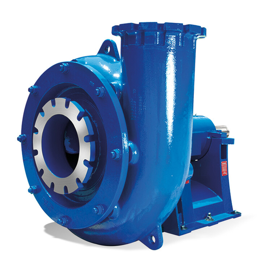
LCC - Metal
KSB AG
Bahnhofplatz 1
D-91257 Pegnitz, GERMANY
FAX
A KSB Company
Slurry Pumps
LCC – H200-610.5M AM1
5012-13012 through 13015
March 13, 2008
Metso Minerals
P162737
G-150234
Constellation Energy
(0 92 41) 71-0
(0 92 41) 71-17 91
LCC - Rubber
KSB S.A.
10/14, rue de la Gare
F-76250 Déville-lès-Rouen, FRANCE
32 82-32 00
FAX
32 82-3290
LCC
13-Mar-08
Advertisement
Table of Contents

Related Manuals for KSB GIW LCC Series


Summary of Contents for KSB GIW LCC Series
-
Page 1: Maintenance Manual
5000 Wrightsboro Road Bahnhofplatz 1 10/14, rue de la Gare Grovetown, Georgia 30813 USA D-91257 Pegnitz, GERMANY F-76250 Déville-lès-Rouen, FRANCE (706) 863-1011 (0 92 41) 71-0 32 82-32 00 (706 855-5151 (0 92 41) 71-17 91 32 82-3290 13-Mar-08 A KSB Company... -
Page 2: Table Of Contents
Contents Page 6.1.8 Shutdown Operating Limits Maintenance Manual 6.2.1 Temperature of the Medium Handled, Ambient Temperature, Bearing Temperature14 General 6.2.2 Switching Frequency 6.2.3 Density of the Medium Handled Safety Shutdown / Storage / Preservation Marking of Instructions in the Manual 6.3.1 Storage of New Pumps Personnel Qualification and Training... - Page 3 Supplements 11. 1 Stuffing Box Throat Bushing Option 11.2 Underwater Pump Operation with Duo-Cone Bearing Seals 11.3 Duo-Cone Seals 11.4 Diverter...
- Page 4 Index Section Page Section Page Accessories 4.4 ..10 Operation, Unauthorized modes 2.8 ..6 Aligning the Pump / Drive Train 5.3.1 ..11 Operational Problems and Solutions 7.7 ..23 Bearing Assembly Clamp Bolts 7.5.15 ...22 Packing the gland 7.5.16 ...22 Bearing Assembly, mounting 7.5.7 ..20 Personnel Qualification and Training 2.2 ..5...
-
Page 5: General
GIW / KSB representative. In particular, non-compliance can, for example, result in: Failure of important machine / unit functions... -
Page 6: Unauthorized Modification And Manufacture
Work on the machine must be carried out only during standstill. The shutdown procedure described in the manual for taking the machine out of service must be adhered to without fail. Pumps or pump units handling media injurious to health must be decontaminated. -
Page 7: Designation
Designation severe slurry duties. Two-stage pressure capability. LCC-M 300-710.5M C M1 Available in sizes LCC 150 - 500 and above. Pump Type Hydraulic Type All casings carry 125 pound, ANSI flange bolting patterns. Discharge Nozzle DN in mm Adapters for conversion to DIN flanges are available. Nominal Impeller Diameter in mm Mechanical Size Seal Type... - Page 8 Any change in the operating conditions should be discussed with your GIW / KSB representative to establish if Unlike mechanical seals, expellers must be carefully the new conditions are suitable for the equipment selected for each application and specific operating conditions.
-
Page 9: Bearings
Basic bearing parts are listed for reference. Note that the suffix can vary depending on configuration and vendor. Replacement bearings are available from GIW/KSB Bearing Bearings Installed Assembly Spherical Double row, Taper roller roller Part number Bench E Type Cone / Cup /... -
Page 10: Permissible Forces And Moments At The Pump Nozzles
4.3.5 Permissible Forces and Moments at the Pump Nozzles Allowable combined branch loads applicable for all GIW slurry pumps. Methods based on ANSI/HI 12.1-12.6-2005 Slurry Pump Standard. Coordinate system per HI/ANSI 9.6.2 and API 610 (see figure). Loads generally exceed HI/ANSI 9.6.2-2008 table 9.6.2.1.4a and API 610-2004, Table 4. -
Page 11: Foundation
certificate supplied with the equipment and issued by the Coupling check and realignment must be done even if responsible approval authorities must be observed and pump and motor are supplied completely assembled and complied with. The test certificate must be kept close to aligned on a common base plate. -
Page 12: Auxiliary Connections
This manual applies to single stage pumps. Procedures Suction lift lines should be laid with a rising slope towards for multistage pumps should be obtained from GIW/KSB the pump and suction head lines with a downward slope sales office. towards the pump. The pipelines should be anchored in... -
Page 13: Shaft Seal
Section 210°F (100°C). Slightly higher temperatures may be seen 7.5.16. Preformed packing rings sets from GIW / KSB are for a brief period during the breaking in of new bearings. recommend. -
Page 14: Suction Strainer
Shutdown / Storage / Preservation until all rotation has stopped. If the any part of the Each GIW / KSB pump leaves the factory carefully system uses a cooling liquid supply, turn that off only assembled. If commissioning is to take place some time after delivery, we recommend that the following measures after the pump has cooled down. -
Page 15: Returning To Service After Storage
operation check run ensure that there is sufficient medium ensure there is no risk to persons or the environment. All relevant laws must be adhered to. liquid available for operating the pump. Maintenance / Inspection 2 The pump is dismantled and stored 7.2.1 Supervision of Operation Before putting the pump into storage carry out all... -
Page 16: 7.2.2.3 Oil Changes
LCC type pumps. For sectional drawings and bills of material relating your specific pump equipment, locate official copy Figure 7.4-1 Impeller Break-Loose Jig documentation provided by GIW / KSB. This may be shipped separately from the pump and will include Impeller Lifting Jig... - Page 17 For impeller removal or installation, grasp the impeller at This excludes hex head bolts at the 3 & 9 o’clock positions the suction eye as shown in Figure 7.4-2. The impeller which mount the expeller plate to the shell (901.14) and can be leveled by turning the adjusting bolt which bears expeller casing to the pedestal (901.13).
-
Page 18: Reassembly
Reassembly tightening the nut according to the torque given in Section 7.5.1 General Instructions 7.5.15. The pump should be reassembled in accordance with the Over-tightening can damage the lock rules of sound engineering practice. Use the sectional Caution washer and allow the locknut to back off drawing and bill of material for guidance. -
Page 19: Mounting Stuffing Box
7.5.4 Installing End Covers and Seals or the face in contact with the shaft shoulder. For ease of The standard bearing housing shaft seal is the Inpro VBX removal, a light coating of anti-seize compound should be type labyrinth seal. Other seal types may be available applied to the inner diameter of the shaft sleeve. -
Page 20: Mounting The Bearing Assembly To Pedestal
7.5.7 Mounting the Bearing Assembly to Pedestal casing. Then move it back towards the pump end approx. After mounting the stuffing box (or mechanical seal 1.0 mm (0.4 inch). This is a preliminary adjustment. Final adapter) loosely onto the pedestal plate, and screwing the adjustment will be made after wet end assembly is adjusting screw (909) with nut (924) an appropriate length complete. -
Page 21: Impeller
7.5.11 Impeller Proper tightening of the bearing housing Caution Coat the shaft threads heavily with anti-seize compound. clamps and adjusting nut is essential to Do not coat the shaft sleeve faces which contact the prevent movement of the rotating assembly during impeller and the step in the shaft. -
Page 22: Tightening Torques
7.5.15 Tightening Torques Flow Control Option Taper Bearing Locknut Assembly Torque The KE stuffing box is a Low Flow design and must be pressure controlled. Flow control can result in burning or Bearing Assembly Locknut Assembly Torque jamming the packing. Actual flow in a properly maintained 35 mm 100 N-m (75 ft-lbs) and adjusted stuffing box is considerably less than shown... -
Page 23: Spare Parts Stock
If any conditions occur, half-life if localized wear occurs. If localized wear is consult your GIW / KSB representative for the NPSH severe, repair as recommended by GIW / KSB before requirements of your pump. - Page 24 Pump speed or impeller diameter should be decreased or make up water Contact your GIW / KSB representative for further specific increased to keep the sump at the highest stable level recommendations regarding system design. A useful possible.
-
Page 25: Trouble Shooting
8.5 Overheating of Pump Casing Trouble Shooting See Piping Connection section for details. Hot process fluid being pumped 8.1 Low Flow Rate Prolonged running against shut head or blocked Verify that the pump is correct for the system discharge. parameters in terms of flow and head. The pump NOTE: This is could create a Dangerous condition!! curve can be used to determine the output, power and Blocked suction... -
Page 26: Torque Values For Metric Fasteners
9 Torque Values for Metric Fasteners not otherwise Specified Tightening Torque Values Class 8.8 Metric Hex Head Capscrews Metric Coarse & Fine Thread Thread Dry (reference only) Oil or Thread Lock Anti-Seize Size in-lbs ft-lbs in-lbs ft-lbs in-lbs ft-lbs M4 X 0.7 M5 X 0.8 M6 X 1 1074... -
Page 27: Notes
NOTES... -
Page 28: General Drawing With List Of Components
General Drawing with List of Components Pump assembly, bill of material and other drawing or special instructions relevant to each order will be attached to the back of this manual.10 Supplements These options may not be Supplements provide additional information for optional equipment. available for your pump See your Bill of Materials for options that were included with your pump. - Page 29 11.1 Stuffing Box Throat Bushing Option (NON-EXPELLER) This reference is provided as a supplement to the LCC Technical Booklet. It gives application and part number data for the LCC Stuffing Box Throat Bushing option. ----------------------------------------------------------- T hr oat Bus hi ng Opt i on St andar d L CC St uf f i ng Box The standard LCC stuffing box, as seen above, uses one ring of compression packing forward of the lantern ring, (between the lantern ring and the pumped fluid).
- Page 30 Failure to operate the seals within the above parameters may result in premature seal failure or oil leakage through the Duo-Cone seals. Any change in the operating conditions should be discussed with your GIW / KSB representative to establish if the new conditions are suitable for the equipment.
- Page 31 11.3 Duo-Cone Seals Rubber Toric Metal Seal Ring Seal rings, rubber torics and housings must be completely clean and free of any oil or dirt. Use a lint free cloth with a solvent that evaporates quickly and leaves no residue. It must be compatible with rubber toric rings.
- Page 32 in place and install the two (2) studs and nuts for the installation tool. Verify that there are no burrs or sharp edges on the shaft that could damage the o-ring. Coat the long set screws with anti-seize and thread them into the tapped holes until the points are 1/8”...
- Page 33 11.4 Diverter One of the product improvements to the GIW LCC Expeller pumps is the addition of a Diverter to further reduce the accumulation of solids in the expeller chamber. This is a urethane part that is pressed into the hub area of the pump casing.
- Page 35 Metso Minerals/Constellation/WAPC Brandon Shores PO P162737 Metso Contract 72805/72806 Equip No: 0-205-P-452A1/B1/A2/B2 GIW Ser No 13012/13/14/15 Duty Point flow: 2,405 gpm head: 175 ft...
- Page 36 5012-13012 through 13015: Mill Product Pump CONTRACT REVIEW GEORGIA IRON WORKS Constellation Energy - Brandon Shores THIS PRINT CERTIFIED FOR DIMENSION Pump Tag #: 0-205-P-452A1 & 0-205-P-452B1 Jonathan Samuel Stan Tam 0-205-P-452A2 & 0-205-P-452B2 13 March 2008 THIS DOCUMENT IS NOT COVERED BY THE GIW UPDATE SERVICE (Future revisions may not be forwarded automatically) 13012LOC...
- Page 37 5012-13012 through 13015: Mill Product Pump CONTRACT REVIEW GEORGIA IRON WORKS Constellation Energy - Brandon Shores THIS PRINT CERTIFIED FOR DIMENSION Pump Tag #: 0-205-P-452A1 & 0-205-P-452B1 Jonathan Samuel Stan Tam 0-205-P-452A2 & 0-205-P-452B2 13 March 2008 THIS DOCUMENT IS NOT COVERED BY THE GIW UPDATE SERVICE (Future revisions may not be forwarded automatically) 13012DT...
- Page 38 Special Tools for Impeller Service: Impeller lift device - p/n 611-7272C-00-0FABS Impeller break loose jig - p/n 611-7963C-00-0FABS...
- Page 39 Special Tools for Impeller Service: Impeller lift device - p/n 611-7272C-00-0FABS Impeller break loose jig - p/n 611-7963C-00-0FABS...
- Page 40 SLYSEL Version 20090112.20090202 GIW Industries, Inc. Item # : 5012-13012-15 Grovetown, GA Reference: Metso Minerals Date: Feb-05-2009 Application: Mill Product Pump , Constellation Time: 16:02:15 LCC-H200-610.5M A 8 X 10 LCC 24 (XH), 125MM O IL CBA MECHANICAL SEAL -------- SELECTED PUMP with ALL VALUES SCALED to NEW SPEED & TURNDOWN --------- 8 x10 LCC 24(XH) C H 7- / 3ME...
- Page 41 Sleeve or Taper Ring's Face Stress is ( 7976. PSI) 41.1(in) from drive end Shaft Stress Excess Safety factor is ( 3.35) at 41.1 (in) from drive end Pump Assembly's Gross Weight is 3778. lb Impeller Material Impeller Impeller Impeller Shaft (28G) (Dry)
- Page 42 GIW part number GIW pump serial number Brief description of the part GIW Industries Inc. • 5000 Wrightsboro Road, Grovetown • GA 30813-9750 USA • Telephone (706) 863-1011 • Fax (706) 860-5897 www.giwindustries.com A KSB Company...
- Page 43 DATE: 03/13/2008 GIW SERIAL NUMBER 13012 ENPC0004 TIME: 14:12 PUMP LCC-H200-610.5M AM1 BILL TO: METSO MINERALS INDUSTRIES, INC. 240 ARCH STREET P.O. BOX 15312 YORK, PENNSYLVANIA 17405-7312 SHIP TO: METSO MINERALS INDUSTRIES, INC. DO BE DETERMINED BALTIMORE, MARYLAND 21075 PROMISED: 12/28/2007 DOCUMENT ID: 13012-BOM ________________________________________________________________________________ PUMP LCC-H200-610.5M AM1...
- Page 44 DATE: 03/13/2008 GIW SERIAL NUMBER 13012 ENPC0004 TIME: 14:12 PUMP LCC-H200-610.5M AM1 __________________________________________________ NAME PLATE DATA _______________ PUMP: LCC-H200-610.5M AM1 GIW SERIAL NBR.: 5012-13012 CUSTOMER P.O.: P162737 P.O. DATE: 06/28/2007 EQUIPMENT #: |________________________________________________| 1. GIW TO PROVIDE PUMP W/ V-BELT DRIVE, SUBBASE, GUARD, SLIDE RAILS, AND MOTOR.
Need help?
Do you have a question about the GIW LCC Series and is the answer not in the manual?
Questions and answers