Megger MFT1700 series User Manual
Mft1700 series multifunction testers
Hide thumbs
Also See for MFT1700 series:
- Quick start manual (8 pages) ,
- Quick start manual (8 pages) ,
- User manual (50 pages)
Table of Contents
Advertisement
Quick Links
Advertisement
Table of Contents

Related Manuals for Megger MFT1700 series


Summary of Contents for Megger MFT1700 series
- Page 1 MFT1700 series Multifunction testers User manual...
-
Page 2: Table Of Contents
Contents SAFETY WARNINGS .................................3 Introduction .....................................4 Overview ....................................4 Front panel and controls ..............................6 Waste electrical and electronic equipment ........................6 Battery and Fuse Location, fitting and replacement ......................6 Operation ..................................7 General operation – all models ............................7 Mode button functions ..............................7 Test inhibit ..................................7 Voltage, frequency, Current and temperature measurement ......................8 Making a voltage measurement ............................8 Continuity / resistance measurement ............................10... -
Page 3: Safety Warnings
Appendix A – Sending, Storing, Deleting and Recalling Test Results .....................33 Appendix B – Downloading data using Bluetooth® ..........................35 Appendix C – Installation category definitions .............................36 Appendix D – Safe working practice ..............................36 Appendix E – Cleaning and maintenance ............................37 Appendix F –... -
Page 4: Introduction
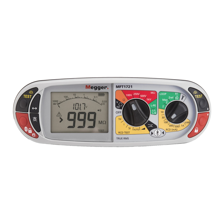
12 Vdc charger socket Introduction Congratulations on your purchase of a genuine Megger Multifunction tester. The MFT1700 series Multi-function tester is a compact instrument designed to perform all of the functions required by the electrical contractor to fully test domestic, commercial and industrial wiring. -
Page 5: Display Symbols
2.1.1 Display Display symbols Symbol Meaning Symbol Meaning Test function locked on (also Warning triangle – instruction to used to indicate a change is refer to this user guide saved in setup) Test lead null active Fuse blown Battery indicator NiMH Touch voltage limit (and Earth... -
Page 6: Waste Electrical And Electronic Equipment
Waste electrical and electronic equipment WEEE The crossed out wheeled bin placed on Megger products is a reminder not to dispose of the product at the end of its life with general waste. Megger is registered in the UK as a producer of electrical and electronic equipment. The Registration No is WEE/HE0146QT Battery and Fuse Location, fitting and replacement Battery type: 6 x 1.5 V Alkaline LR6 (AA) or NiMH HR6 rechargeable... -
Page 7: Operation
3. Operation General operation – all models 3.1.1 Switching on Turn the rotary knob away from the off position. The instrument will perform internal self tests then display the appropriate test screen, depending on the position of the function knobs. 3.1.2 Switching off Turn the primary function knob to the OFF position. -
Page 8: Voltage, Frequency, Current And Temperature Measurement
3.3.3 Earth loop impedance Touch voltage exceeds 50 V (or 25 V depending on instrument configuration) Supply voltage over range or under range Supply frequency out of specification 3.3.4 RCD testing Touch voltage detected or predicted to exceed 50 V (or 25 V depending on instrument configuration) Supply voltage over range or under range Supply Frequency out of specification 3.3.5... -
Page 9: Frequency Measurement
Connection (a) Connection (b) Note: When connecting all three test leads (eg Phase, Neutral and Earth) or the mains plug test lead, the voltage displayed is the high- est of the three possible voltages. On models with a dedicated mV range this is selected using the Mode button to select mV mode. -
Page 10: Continuity / Resistance Measurement
Switch probe In the V/mV/ºC mode all measurements except temperature can be made with the remote switch probe. Tests are automatic and do not require the test button to be pressed. Connect the switch probe to the switch probe socket. The probe replaces the standard RED test lead and can now be used as a normal test probe. -
Page 11: Making A Continuity Measurement
Making a CONTINUITY measurement Set the Primary (Left) range knob to range. (The position of the right hand rotary range knob must not be in position). Connect two test leads to the L1 (+ve) and L2 (-ve) terminals on the instrument. A continuity measurement is made automatically. -
Page 12: Buzzer Threshold
Buzzer threshold If the measured resistance is less than the buzzer threshold, the buzzer will sound. The resistance at which the buzzer stops sounding can be changed to meet individual test requirements. Refer to the SETUP section 10 of this guide. Selectable limits of 0.5 Ω, 1 Ω, 2 Ω, 5 Ω, 10 Ω, 20 Ω, 50 Ω, 100 Ω. -
Page 13: Insulation Test Lock
To start test, press and hold either of the TEST buttons, , on the instrument. Release the test button after the displayed reading has settled. Circuit will now discharge safely. Note: A 1000 V warning is displayed whenever the 1000 V range is selected for the first time and the TEST button is pressed. Insulation test lock To lock an insulation test ON, hold down either of the TEST buttons followed by either of the RED LOCK buttons. -
Page 14: Range Selection And Test Leads
Connecting the 3rd (Blue) lead enables the “3 wire loop test 3Lo, as below and “reverse polarity detection”. Test Options in L-PE mode: In L-PE mode the MFT1700 series offer 3 types of loop test: 3Lo – A 3-wire low current loop impedance test. This test requires all three connections. -
Page 15: Making A Loop Impedance Measurement
The test mode is displayed as below: Default mode 1st Press 2nd Press Note: RCDs can still trip when performing a “non-trip” loop test if there is an existing high level of fault current flowing in the Earth conductor, or the RCD is not operating within specification. 7.1.2 L-N or L-L circuits: ... - Page 16 Press the Function key <-> to select the “2Hi” mode. The RCD will not trip, so there is no need to use the 3Lo and 2Lo modes. Press TEST to start the test sequence. This can be automated in SETUP so the test starts when contacting the circuit. See section 10 –...
- Page 17 Connect test leads as below, with the Red test lead connected to the L1 (Red terminal on the MFT and the Green test lead connected to the Green (L2) terminal. The Blue (L3) test lead can be connected to enable “reverse polarity” warnings ...
- Page 18 MFT1710 MFT1720 and MFT1730 Connect test leads as below, with the Red test lead connected to the L1 (Red terminal on the MFT, the Green test lead connected to the Green (L2) terminal and the Blue test lead to the Blue (L3) terminal. ...
-
Page 19: Phase To Neutral (Or Phase To Phase) Testing
Press the Function key <-> to select the “2Lo” mode. Press TEST to start the test sequence. On completion of the test, the display will show the loop resistance on the large display segments, and the fault current on the small display segments. -
Page 20: Prospective Fault Current And Short Circuit Calculation (Pfc & Pscc)
Press and release the TEST button to start the test. On completion of the test, the display will show the loop resistance on the large display segments, and the fault current on the small display segments. Prospective Fault Current and Short Circuit calculation (PFC & PSCC) The prospective fault current and short circuit current of a circuit is automatically calculated when making a loop impedance test. -
Page 21: Making An R1+R2 Loop Impedance Measurement
Connect the test leads to the Phase (L1) and Earth (L2) or Phase (L1) and Neutral (L3) terminals on the tester depending on the selection in (.1) above. Connect the test leads to the Phase and Earth conductors or Phase and Neutral conductors as required. If using the mains plug test lead connect to the first supply outlet. -
Page 22: Measurement Methods And Sources Of Error
Ensure that potential sources of noise in the installation are isolated (switched off), eg: automatically switched loads or motor controllers Residual Current Device testing The MFT1700 series can perform the following RCD tests: 1/2I Non-tripping test at half the rated RCD trip current for 2 seconds, during which the RCD should not trip Tripping test at the rated RCD trip current. -
Page 23: Making An Rcd Measurement
The characteristics of each RCD type is detailed below: RCD Type Operate with AC Selective RCD Operate with AC and Operate with AC residual earth Operates on type AC with Description pulsed DC residual Pulsed DC and Smooth DC currents time delay or type A with time earth currents. -
Page 24: I Rcd Current Rating (Tripping Test On 30Ma Rcd)
Press the TEST button. The Display should show one of the following: If the RCD Trips, the MFT will flash the “trP” warning and then display the following: NOTE: For Type AC RCDs there is no need to perform a 180° test on the ½I mode, as the test uses a full AC waveform. 1 x I RCD current rating (Tripping test on 30 mA RCD) ... -
Page 25: I Rcd Current Rating (Tripping Test On 30Ma Rcd)
*any value below 300ms indicates an RCD has tripped in an adequate time. Press the mode button to select 180 Repeat the above test. Record the higher of the two values. 5 x I RCD current rating (Tripping test on 30 mA RCD) Repeat the test sequence in 8.4 but with the LEFT rotary range knob to the RCD test range. -
Page 26: Dc Sensitive/Pure Dc Rcd Test
Press the TEST button The RCD should trip and the display show the trip current in mA. If the RCD fails to trip, >***mA is displayed, where *** = 110% of the nominal RCD trip currnet. Type A (DC Sensitive) RCD test ‘Type A’... -
Page 27: Variable Rcds (Not Mft1710)
3 Phase RCD testing The MFT1700 series is designed to test RCDs on 3 phase installations. To test RCDs in a 3 phase system each RCD is tested as a single RCD, from Phase to earth. As described in section 8.1 to 8.5. - Page 28 Connect the Green (L2) terminal of the MFT to the upstream phase of an RCD on a separate phase. Press the TEST button. The MFT will display the trip time of the RCD. 8.12 Touch voltage display The voltage to which an earth conductor may rise during an RCD test. The limit for touch voltage is 50 Vac or 25 Vac, depending on the environment.
-
Page 29: Touch Voltage Display
Earth resistance measurement The Megger MFT family of test instruments offers a unique solution to the measurement of earth or ground electrode (rod) supporting 2 and 3 wire measurements: For the principles of earth resistance testing go to Appendix F... -
Page 30: Making A Measurement - Three Terminal Resistance Measurement
Making a measurement – Three terminal resistance measurement MFT1730 Connect the instrument as below. Set the rotary selector switch to the position. TEST Press and release the button. The instrument will perform pre-measurement check, the status of which will be indicated on the display. -
Page 31: Setup Options
Setup options The Setup options allow the MFT to be configured to best suit the type of testing to which it will be used. To enter SETUP, right (secondary) range knob to SETUP. Set the left (primary) range knob to any function other than OFF. ... -
Page 32: Startup Warnings
The following warning messages may be displayed during the testing process. Characters which appear in the aux (small) digit field on the display are shown here in a slightly smaller font size. 11.1 Startup warnings “UNC” -Instrument is un-calibrated 11.2 Battery “bAt”... -
Page 33: Appendix A - Sending, Storing, Deleting And Recalling Test Results
Test results can be stored in the MFT, or downloaded immediately to a Bluetooth compatible device running PowerSuite Mobile, or both. See section 10 Setup, Test results are stored in “Folders” against a set of circuit references as below: Folders: 000 to 255 Job number –... - Page 34 If TEST is displayed, this indicates further data is available for the displayed result. Use the LEFT TEST button to display this as required. E.g. for Insulation, the test voltage is available for viewing. Sending stored Test Results via Bluetooth Run Megger Download Manager Using the approprate driver, follow the on-screen instructions. Sending individual (Blobbing) Test Results Note that in order to Blob test data, the Store Mode needs to be set to Bluetooth or internal and Bluetooth.
-
Page 35: Appendix B - Downloading Data Using Bluetooth
Appedix B- Downloading data via buetooth Bluetooth Pairing (PC or Laptop) Turn your MFT ‘on’ to any setting, and turn the smaller dial to the settings (‘spanner’) position to enter the setup mode. Press the button on the MFT until you see ‘StR’ appear on the display. At this point you should ensure that ‘bt’ is ... -
Page 36: Appendix C - Installation Category Definitions
The Megger MTB7671 test box is available for checking all electrical functions of the multi-function tester (excluding earth tests) between calibration dates. -
Page 37: Appendix E - Cleaning And Maintenance
Appendix E - Cleaning and maintenance The MFT1700 should only be opened or repaired by an approved Megger service or by Megger Instruments Limited. To clean the instrument, use a damp cloth or isopropyl alcohol if available. To clean the display window only use a lint free cloth. -
Page 38: General Specification
General Specification Accuracy Insulation test: 1000 Volts 10 kΩ - 999 MΩ ±3% ±2 digits 500 Volts. 10 kΩ - 500 MΩ ±3% ±2 digits >500 MΩ ±10% ±4 digits 250 Volts. 10 kΩ - 250 MΩ ±3% ±2 digits >250 MΩ ±10% ±4 digits 100 Volts. - Page 39 Voltage: Intrinsic accuracy: ±2% ±1 V EN61557-1 Range: 10 V to 600 V Phase rotation indication. Max service error: ±5% ±2 digits Frequency: Intrinsic accuracy: ±0.5% ±2 digits Resolution: 0.1 Hz EN61557 Range: 15 Hz to 400 Hz Max service error: ±5% ±3 digits Earth Test Ranges: Intrinsic accuracy: ±2.0% ±3 digits...
- Page 40 Environmental Specification. Temperature Operational range: -10 °C to +55 °C Storage range: -25 °C to +70 °C Humidity Operating humidity: 90% R.H. at +40 °C max. Altitude 2000 m to full safety specification. Weight: 1000 g ±10% including batteries but excluding test leads, accessories and carry case. Dimensions: 150 mm high x 85 mm wide x 235 mm deep (6 in.
-
Page 41: Repair And Warranty
RA number. You may track the progress of your return on line at www.megger.com Approved Service Centres A list of Approved Service Centres may be obtained from the UK address above, or from Megger’s website at www.megger.com... - Page 42 T +61 (0)2 9659 2005 F +61 (0)2 9659 2201 E ausales@megger.com This instrument is manufactured in the United Kingdom. The company reserves the right to change the specification or design without prior notice. Megger is a registered trademark. MFT1700_UG_EN_V06 03/15 www.megger.com...
Need help?
Do you have a question about the MFT1700 series and is the answer not in the manual?
Questions and answers
can the MFT1710 test 110v RCDs ?