
Related Manuals for Ultraflex MasterDrive


Summary of Contents for Ultraflex MasterDrive
- Page 1 Installation, maintenance and owner's manual POWER ASSISTED STEERING SYSTEM ULTRAFLEX PARTNER 28117/f 17/12/2014) (COD. 74204K - REV 06) dr./dis./des. n°...
- Page 2 Products for pleasure boats are constantly tested to check their conformity with the 2013/53/EU. "ULTRAFLEX has over 80 years of experience in the marine industry and is a world leader in the production of mechanical, hydraulic and electronic steering systems, control boxes and steering wheels for any kind of pleasure, fishing or commercial boats.
-
Page 3: Table Of Contents
ULTRAFLEX Installation, Maintenance and Owner's Manual TABLE OF CONTENTS DOCUMENT REVISIONS ..............................5 MANUAL USE AND SYMBOLS USED ........................... 6 INFORMATIVE LETTER ..............................7 WARRANTY ..................................7 SECTION 1 - PRODUCT DESCRIPTION PRODUCT DESCRIPTION AND FEATURES ......................8 WARNINGS FOR THE CORRECT USE OF THE PRODUCT ................9 SYSTEM CONFIGURATIONS .......................... - Page 4 ULTRAFLEX Installation, Maintenance and Owner's Manual SECTION 5 - MAINTENANCE ROUTINE MAINTENANCE ............................ 45 5.1.1 CLEANING OPERATIONS ............................. 45 5.1.2 ANNUAL INSPECTIONS ............................45 STEERING WHEEL DISASSEMBLY ........................45 TROUBLESHOOTING ............................46 SECTION 6 - DISMANTLING DISMANTLING ............................... 47 page 4...
-
Page 5: Document Revisions
ULTRAFLEX Installation, Maintenance and Owner's Manual DOCUMENT REVISIONS Rev. Date Revision description 10/02/2012 First edition 08/03/2013 Addition of automatic start 25/06/2013 Addition of Slave helm 29/10/2013 Addition of start customization 17/07/2014 Use with inboard cylinders has been added 04/11/2014 List modification of inboard cylinders... -
Page 6: Manual Use And Symbols Used
ULTRAFLEX Installation, Maintenance and Owner's Manual MANUAL USE AND SYMBOLS USED THE INSTALLATION AND MAINTENANCE MANUAL is the document accompanying the product from sale to replacement and discharge. The manual is an important part of the product itself. It is necessary to read carefully the manual, before ANY ACTIVITY involving the product, handling and unloading included. -
Page 7: Informative Letter
We remind you that only marked steering systems must be used on the boats marked We inform you that the ULTRAFLEX warranty is null if some ULTRAFLEX components are installed on a steering system together with products of other brands. -
Page 8: Section 1 - Product Description
1 PRODUCT DESCRIPTION 1.1 Product description and features All ULTRAFLEX hydraulic steering systems are designed in conformity with UNI-EN-ISO 10592 and A.B.Y.C. P21 regulations. All ULTRAFLEX steering systems can operate at temperatures between -18°C (0°F) and +77°C (+170°F). All the components are made for the marine environment, using materials and working processes which offer long life and safety under the most extreme conditions. -
Page 9: Warnings For The Correct Use Of The Product
WARNING All ULTRAFLEX steering systems must not be installed on boats equipped with engines whose maximum horsepower is higher than the horsepower rating approved by boat manufacturer. WARNING ULTRAFLEX steering systems must not be installed on race boats. -
Page 10: Helm Technical Features
ULTRAFLEX Installation, Maintenance and Owner's Manual 1.5 Helm technical features - Available in three different displacement sizes: 32 cc (1.95 cu.in) , 40 cc (2.44 cu.in) and 50 cc (3.05 cu.in). - Front Mount and Tilt Mount versions. Tilt Mount version is suitable... - Page 11 ULTRAFLEX Installation, Maintenance and Owner's Manual NOTICE For TILT version dimensions, refer to point 1 in paragraph 3.4. Release pressure of Model Mounting Displacement/ Revolution Application Steering wheel max.Ø relief valves Max Ø 711 mm - 28" UH32-F front mount 32 cc- 1.95 cu.
-
Page 12: Power Unit Technical Features
ULTRAFLEX Installation, Maintenance and Owner's Manual 1.6 Power unit technical features - 12VDC Motor - 90° swiveling fittings for easy installation - Semitransparent 2 litre (0.52 gal) tank gives immediate level vision - Vented filler plug - 40A fuse - Maximum rated current of the power unit 35A... - Page 13 ULTRAFLEX Installation, Maintenance and Owner's Manual APPLICATION EXAMPLE - OVERALL DIMENSIONS 203 mm - 7.99" 130 mm - 5.12" 110 mm - 4.33" 178 mm - 7.01" 198 mm - 7.80" 158 mm - 6.22" NOTICE: Consider the wiring harness and hydraulic hose dimensions...
-
Page 14: User Interface Technical Features
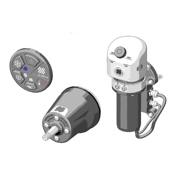
- Backlit "soft touch" panel On push button (red when in standby/ white when on) Fishing mode selection push-button (backlit in white) MasterDrive™ mode selection push button (backlit in Fishing mode indicator led (blue when on) white) Malfunction signalling led (red) MasterDrive™... -
Page 15: Section 2 - Transport
MD KIT - TILT APPLICATION: n° 1 helm (UH32-T or UH40-T or UH50-F) n° 4 litres of hydraulic oil OL 150 ULTRAFLEX NOTICE: cylinders and hydraulic hoses (Kit OB-SVS and Kit OB-MD) are ordered and packed separately (see the relevant installation manuals). -
Page 16: Dual Station Packaging Contents
1 helm (with the same cylinder capacity as the Master helm: UHD32-T or UHD40-T or UHD50-T according to the Master helm) n° 1 litre of hydraulic oil OL 150 ULTRAFLEX n° 1 Slave helm communication cable n° 1 straight fitting n°... -
Page 17: Section 3 - Installation
3 INSTALLATION 3.1 Safety rules during installation RESPECT STRICTLY the following safety rules: ULTRAFLEX declines all responsibility in case the user does not follow these rules and it is not responsible for negligence during the use of the system. DANGER DO NOT PUT HANDS BETWEEN THE MOVING PARTS. - Page 18 ULTRAFLEX Installation, Maintenance and Owner's Manual EXAMPLE OF HYDRAULIC CONNECTION OF THE UH32-F SINGLE STATION WITH SINGLE CYLINDER MASTER HELM WARNING: Check the correct connection of the Kit OB-MD (8) between the helm and the power unit; the hose coming from fitting "T"...
- Page 19 ULTRAFLEX Installation, Maintenance and Owner's Manual MASTER HELM REF. MARKING DESCRIPTION COMPONENT Fitting to connect the oil return hose to the power unit tank Helm Fitting to connect the high pressure hose from the power unit Helm Fitting to connect the helm and the cylinder on STARBOARD side...
- Page 20 ULTRAFLEX Installation, Maintenance and Owner's Manual EXAMPLE OF HYDRAULIC CONNECTION OF THE UH32-F and UHD32-F DUAL STATION WITH SINGLE CYLINDER MASTER SLAVE HELM HELM If the system with single station is present, drain all the oil out of the system without dispersing it into the sea.
- Page 21 ULTRAFLEX Installation, Maintenance and Owner's Manual MASTER SLAVE HELM HELM REF. MARKING DESCRIPTION COMPONENT Fitting to connect the oil return hose to the power unit tank Master helm Fitting to connect the hose coming from Slave helm T Master helm...
-
Page 22: Necessary Tools
ULTRAFLEX Installation, Maintenance and Owner's Manual 3.2Necessary tools Open end Open end Hole saw Hole saw Drill Drill bit Drill bit MOLYKOTE® 1000 Torque wrench wrench wrench Ø 5 / 0,2" Ø 6,5 / 0,25" Ø 75 / 3" Ø 50 / 2"... - Page 23 If necessary, replace the damaged pipe. Connect the hydraulic hoses ULTRAFLEX kit OB-MD as shown in the picture on page 18 for single station applications and on page 20 for dual station applications.
- Page 24 ULTRAFLEX Installation, Maintenance and Owner's Manual 5 By using a 5 mm Allen wrench, fix the helm to the dashboard by means of screws (3) nuts (4) and washers (5) after positioning flange (6) in the rear part of the dashboard and flange (7) with spacers (8) in the front part of it (not supplied for 50cc helms).
- Page 25 ULTRAFLEX Installation, Maintenance and Owner's Manual Put seal (10) on the hub paying great attention not to damage it, especially when making it pass through the the milled profile of the key. NOTICE: Make sure hole (11) is positioned downwards so that condensation can be drained.
-
Page 26: Installation Of The Tilt Mount Helm
ULTRAFLEX Installation, Maintenance and Owner's Manual 3.4 Installation of the TILT mount helm CAUTION min. 510 mm [20,08 in.] Tilt X66 is supplied separately. Select a suitable place for the steering station. Make sure that there is enough manoeuvering space for the steering wheel and for the helm and its pipes and fittings. -
Page 27: Installation Of The Power Unit
For the connection to the cylinder, use ALWAYS SVS series hoses. If the system is used with hoses, which are not supplied by ULTRAFLEX, verify that the system is dimensioned to bear pressures up to 105 bar (1500 psi). - Page 28 ULTRAFLEX Installation, Maintenance and Owner's Manual 3.5 Installation of the power unit NOTES FOR CORRECT INSTALLATION - It is advisable to install the power unit far from heat sources, humid areas and fuel tanks in order to ensure its longer duration in good working and efficiency conditions.
- Page 29 ULTRAFLEX Installation, Maintenance and Owner's Manual 2 Fix the power unit to the wall or to the floor by using the four self-tapping screws (7) and washers (8) with a proper torque according to the support type, without exceeding 8 Nm (5,9 lb ft).
- Page 30 WARNING Before installing an autopilot, contact ULTRAFLEX Technical Assistance Center. ULTRAFLEX declines any responsability about the compatibility and the correct operation of the system after installing an autopilot. After checking compatibility, remove vent from T fitting (9) by unscrewing nut (12) (see previous page).
-
Page 31: Installation Of The User Interface
ULTRAFLEX Installation, Maintenance and Owner's Manual 3.6 Installation of the user interface 1 Position the user interface so that it does not hinder other controls or that it is not hindered by them. Refer to the overall dimensions indicated in paragraph 1.7 to make sure the interface can be installed in the chosen position. -
Page 32: Electrical Connections
Installation, Maintenance and Owner's Manual 3.7 Electrical connections WARNING ULTRAFLEX is not to be held responsible for possible damages or malfunctions deriving from operation not workmanlike performed. DANGER Do not bend the electrical cables near the power unit fairleads: the system explosion-proof safety would no longer be ensured. - Page 33 APS (Automatic Power Selector) to use the charge of two batteries: in single-engine systems, the power cable must be connected to the engine battery and to the service battery. Masterdrive Service distribution panel Power...
- Page 34 ULTRAFLEX Installation, Maintenance and Owner's Manual In twin-engine system, it must be connected to both batteries. Masterdrive Power cable Fuse on Engine Engine cable Magneto-thermal Magneto-thermal switch switch Positive Positive pole pole Battery disconnecting Battery disconnecting Negative Negative device device...
- Page 35 ULTRAFLEX Installation, Maintenance and Owner's Manual If a APS is not used, it is necessary to connect the power cable to the engine battery. Masterdrive Power cable Engine Fuse on cable Positive pole Engine Polo negativo negative pole del motore...
-
Page 36: Key Cable
ULTRAFLEX Installation, Maintenance and Owner's Manual 3.7.2Key cable Two engine keys can be connected to the cable. The black wire and the red wire are used in the same way; therefore, a wiring diagram is not necessary. In single-engine systems, it is sufficient to connect one key wire to the positive wire of the panel key. - Page 37 ULTRAFLEX Installation, Maintenance and Owner's Manual SINGLE STATION DUAL STATION Power supply Power supply Key cable Master helm cover Cover cable Key cable "Y" cable Cover cable Master helm cover Slave helm cover page 37 of 143 POWER ASSISTED STEERING SYSTEM...
-
Page 38: System Filling And Bleeding
- Mobil DTE 11M NOTICE ULTRAFLEX will not be able to ensure the compatibility of the above mentioned oils with OL150 if the oil manufacturers vary their formulation; in particular, it will not be able to ensure its compliance with standard ISO 10592 concerning hydraulic steering systems. -
Page 39: Single Cylinder System Bleeding
ULTRAFLEX Installation, Maintenance and Owner's Manual 2 Turn the system on. Oil starts circulating in the system, filling the hydraulic hoses and lowering the oil level inside the tank. Top up the tank until reaching the maximum level. 3.8.2 Single cylinder system bleeding... -
Page 40: Single Steering Station/Dual Cylinder
ULTRAFLEX Installation, Maintenance and Owner's Manual - Open the other bleed valve and move the oil recovery tank to the other side. Holding the cylinder body in this position, turn the steering wheel as shown in picture 4, until oil without air bubbles comes out of the bleed valve. -
Page 41: Dual Steering Station/Dual Cylinder
ULTRAFLEX Installation, Maintenance and Owner's Manual - Follow the same bleeding procedure described in paragraph 3.8.2 starting from the Slave helm and repeat it for the Master helm. - Repeat the procedure at least 3 times to ensure the absence of air in the system. -
Page 42: Section 4 - System Use
ULTRAFLEX Installation, Maintenance and Owner's Manual 4 SYSTEM USE On push button Indicator lights Master Drive™ Cruise Malfunction warning light Fishing 4.1.1 (Preset) Manual start 1 Turn the engine key on the dashboard. After a system self-checking cycle, the user interface goes to stand-by mode and the on push button lights up in red. -
Page 43: Start Customization
ULTRAFLEX Installation, Maintenance and Owner's Manual 4.1.2 Start customization It is possible to customize the system start by selecting the (preset) manual mode or automatic mode and to select the system mode during the first start. These settings can be changed by the user. -
Page 44: System Use
ULTRAFLEX Installation, Maintenance and Owner's Manual 4.2 System use It is possible to select three different power levels according to sailing conditions, by pressing the relevant push buttons. The indicator lights will show the enabled mode: FISHING - low speed, good steering comfort and minimum power consumption CRUISE - cruise speed, optimum steering comfort and low power consumption MASTER DRIVE™... -
Page 45: Section 5 - Maintenance
3.7 and in bleeding procedures for ULTRAFLEX cylinders. Check the hose and the entire system wear, the nut and bolt tightening every six months and make sure that they are not damaged. Clean the system using water and non-abrasive soap. -
Page 46: Troubleshooting
WARNING Whenever the following checks need the removal and/or disassembly of the steering system components, such operation must be carried by specialized staff. ULTRAFLEX offers general information only and is not responsible for any consequences resulting from incorrect disassembly. PROBLEM... -
Page 47: Section 6 - Dismantling
ULTRAFLEX Installation, Maintenance and Owner's Manual 6 DISMANTLING 6.1 Dismantling When for any reason, the steering system is put out of service, it is necessary to follow some rules in order to respect the environment. Sheaths, pipelines, plastic or non-metallic components must be disassembled and disposed of separately. - Page 48 ULTRAFLEX S.p.A. 16015 Casella (Genova) Italia - Via Crose, 2...
Need help?
Do you have a question about the MasterDrive and is the answer not in the manual?
Questions and answers