Advertisement
Quick Links
1
2
3
4
24
23
22
21
20
19
18
17
16
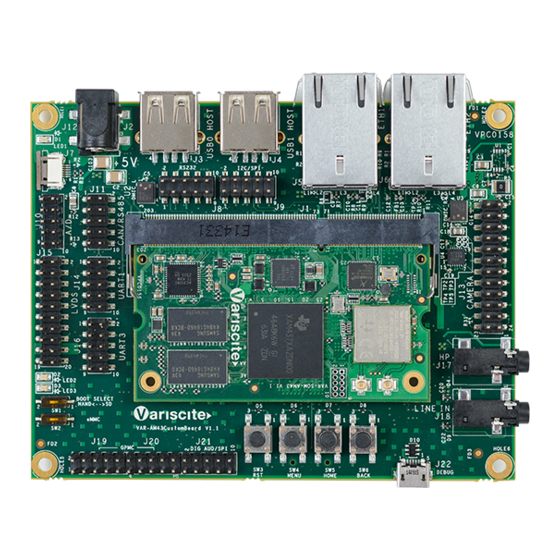
Top side:
1. 5V DC In Jack (J12)
2. USB0 Host
3. RS232 Header (J8)
4. USB1 Host
5. I2C / SPI Connector (J9)
6. 10/100/1000Mbps ETH1 (J5)
7. 10/100/1000Mbps ETH2 (J6) *
8. Camera Header
9. Headphones Jack (J17)
10. Line In (J18)
11. USB Debug (J22)
12. USER Button3 (SW6)
13. USER Button2 (SW5)
14. USER Button1 (SW4)
15. Reset Button (SW3)
*
NOTE:
VAR-DVK-AM43 supports dual GbE w/o Wi-Fi / BT
VAR-DVK-AM43_W supports single GbE and Wi-Fi /B
VAR-SOM-AM43 based on TI AM437x
Evaluation Kit Quick Start Guide
6
7
5
15
14
13
12
11
16. Digital Audio / SPI (J21)
17. GPIO Headers (J19 / J20)
18. Boot select switches
19. UART3 Header (J16)
20. LVDS Display Connector
21. UART1 Header (J14)
22. A2D Header (J10)
23. CAN / RS-485 Header
24. Capacitive Touch (J7)
Bottom side:
25. microSD connector (J103)
26. OV2659 Image-sensor
27. USB0 OTG
28. Resistive Touch
29. RTC Battery Holder
26
8
9
10
Evaluation Kit initial Setup
1. Carefully remove the 7" LCD and VAR-AM43CustomBoard board from the
package.
2. Connect the 7" LCD Touch and Display cables to the Evaluation Kit connectors
J7, J15 respectively as shown in the upper left picture.
Note: Display cable connector pins 1, 2 (colored in red) should be connected to
J15 pins 1, 2 respectively.
Touch cable – connect the cable with metal contacts facing down.
3. Plug the USB type A to micro B cable between the USB debug connector (J22)
and a PC USB port.
4. Plug the wall adapter's connector into the VAR-AM43CustomBoard
5V power jack (J12).
27
25
28
29
Advertisement

Related Manuals for Variscite VAR-SOM-AM43


Summary of Contents for Variscite VAR-SOM-AM43
- Page 1 VAR-SOM-AM43 based on TI AM437x Evaluation Kit Quick Start Guide Top side: Evaluation Kit initial Setup 1. 5V DC In Jack (J12) 16. Digital Audio / SPI (J21) 2. USB0 Host 17. GPIO Headers (J19 / J20) 1. Carefully remove the 7” LCD and VAR-AM43CustomBoard board from the 3.
- Page 2 VAR-SOM-AM43 based on TI AM437x Evaluation Kit Quick Start Guide Setting the Host PC for Debug Burning Recovery File System 1. Download any PC terminal program. Variscite suggests using Putty Please refer to Variscite’s wiki pages at: http://variwiki.com/index.php?title=VAR-SOM- 2. Set PC terminal software parameters as follows:...
Need help?
Do you have a question about the VAR-SOM-AM43 and is the answer not in the manual?
Questions and answers