Table of Contents
Advertisement
Quick Links
Advertisement
Table of Contents

Related Manuals for PIE PIECAL 820


Summary of Contents for PIE PIECAL 820
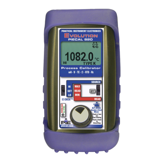
- Page 1 PIECAL 820 PIECAL 820 Multifunction Multifunction Process Calibrator Process Calibrator mA • V •TC • Ω • RTD • Hz mA • V •TC • Ω • RTD • Hz Operating Instructions Operating Instructions 99 Washington Street Melrose, MA 02176...
-
Page 2: Table Of Contents
Contents General Operations Field & Bench Use, Changing Batteries ..... 2 Storing EZ-CHECK Outputs, Connections ....3 Basic Operation Switches & Knobs ..........4, 5 Double Click Menus ..........6, 7 Stepping, Auto Off, Backlight ........8, 9 Functions and Hookup Diagrams Milliamp Source mA .............. - Page 3 General Information Technician friendly operation The unique and intuitive EZ-DIAL Double Click Menu makes it easier to setup than other multifunction calibrators. Uses the same menus as the single function PIECAL Evolution Calibrators. Icons on the display indicate where to plug in the test leads. Use it as a milliamp and voltage calibrator Source 0 to 24.00 mA, 0 to 10.25 V &...
-
Page 4: Field & Bench Use, Changing Batteries
PIECAL 820 comes with a carrying case designed for hands- free operation and a rubber boot with a built-in tilt stand. The PIECAL 820 is held in the case by elastic straps for use with the carrying case open. The tilt stand is easily raised by pulling the stand until it locks into place. -
Page 5: Storing Ez-Check Outputs, Connections
SET position on the EZ-CHECK switch. Connections PIECAL 820 has banana jacks compatible with standard banana plugs or retractable safety banana plugs. Included with your calibrator are a pair of test leads with alligator clips for mA, V &... -
Page 6: Basic Operation
The values stored in the HI and LO positions are also used for Auto Stepping. READ: Slide the switch to the SET position. The PIECAL 820 will display the current reading from the sensor or device being measured. Slide the switch to MAX and the highest value measured since turn-on or MAX/MIN reset will be displayed;... - Page 7 SELECTING FUNCTIONS The EZ-DIAL knob is used to setup the PIECAL 820 to match the instrument to be calibrated or signal to be measured. Each time you turn on the PIECAL 820 the LCD displays the following screen for about 1 second followed by operating in the function used the last time it was operated.
-
Page 8: Double Click Menus
Operating Instructions Double Click Menus Double click the EZ-DIAL knob to access the Double Click Menus to select each function and the options for each function. Available choices are shown in grey. Source mA & Simulate 2 Wire Transmitters MAIN >... - Page 9 Operating Instructions Double Click Menus Source & Read Thermocouples > EXIT (1/2) FUNCTION UNITS °C °F T/C TYPE K E T R S B N L U G C D P COLD JUNC Source RTD > EXIT (1/2) FUNCTION UNITS °C °F Pt 100 a=3850...
-
Page 10: Stepping, Auto Off, Backlight
Operating Instructions Double Click Menu - STEPPING, AUTO OFF & BACKLIGHT To change the Automatic Stepping settings Double click the DIAL KNOB at any time the unit is on and the following typical display (will be different for each FUNCTION) will appear for 15 seconds: MAIN >... -
Page 11: Stepping, Auto Off, Backlight
Operating Instructions Double Click Menu - STEPPING, AUTO OFF & BACKLIGHT STEPS/RAMP - pressing the knob will cycle through 2, 3, 5, 11 and RAMP. The endpoints of the steps or ramp are based on the values stored in the HI and LO EZ-CHECK outputs. 2 steps will automatically switch between the values stored in the HI &... -
Page 12: Source Ma
MODE. Choose either mA or % and whether you need the 250Ω HART resistor active in the loop. Connect the output leads of the PIECAL 820 to the inputs of the device being calibrated, making sure to check polarity. Red lead to the plus (+) input and black lead to the minus (-) input. -
Page 13: Simulate 2 Wire Transmitters
MODE. Choose either mA or % and whether you need the 250Ω HART resistor active in the loop. Connect the output leads of the PIECAL 820 to the inputs of the device being calibrated, making sure to check polarity. Red lead to the plus (+) input and black lead to the minus (-) input. -
Page 14: Read Ma
MODE. Choose either mA or % and whether you need the 250Ω HART resistor active in the loop. Connect the red input lead (+) of the PIECAL 820 to the more positive point of the break and the black input to the more negative point. -
Page 15: Power/Measure Transmitters
(+) input of the device and the black source lead to the minus (-). The PIECAL 820 supplies a nominal 24 volts DC at 24 mA to the 2 Wire Transmitter. The current passed by the transmitter will be accurately displayed by the PIECAL 820. -
Page 16: Source Mv/V
Select V for the FUNCTION and 10V or 80 mV for the RANGE. Connect the output leads of the PIECAL 820 to the inputs of the device being calibrated, making sure to check polarity. Red lead to the plus (+) input and black lead to the minus (-) input. -
Page 17: Read Mv/V
Select V for the FUNCTION and 10V, 60V or 80 mV for the RANGE. Connect the red input lead (+) of the PIECAL 820 to the more positive point of the break and the black input to the more negative point. -
Page 18: Thermocouple Source T/C
T/C Type (J, K, T, E, R, S, B, N, G, C, D, L (J-DIN), U (T-DIN) or P (Platinel II) and internal COLD JUNC ON or OFF (ON is the default). Connect the PIECAL 820 to the inputs of the device being calibrated using the proper type of thermocouple wire via the miniature thermocouple socket. -
Page 19: Read T/C Sensors
T/C Type (J, K, T, E, R, S, B, N, G, C, D, L (J-DIN), U (T-DIN) or P (Platinel II) and COLD JUNC ON or OFF (ON is the default). Connect the PIECAL 820 to the inputs of the device being calibrated using the proper type of thermocouple wire via the miniature thermocouple socket. -
Page 20: Source Resistance
Select OHMS for the FUNCTION, 400Ω or 4000Ω for the RANGE. Disconnect all sensor wires from the devices to be calibrated and connect the PIECAL 820 to the inputs of the device using 2, 3 or 4 wires. Instantly output your SPAN and ZERO output settings by moving the EZ-CHECK switch between HI and LO. -
Page 21: Read Resistance & Check Continuity
Signals above the maximum scale are limited by protection circuitry with “OVER RANGE” on the display and the red OVERLOAD LED lit. The PIECAL 820 measures the input signal and constantly updates the display with the current reading. Move the EZ-CHECK switch to MAX to see the highest reading and to MIN to see the lowest reading. -
Page 22: Rtd
RTD type. Disconnect all sensor wires from the devices to be calibrated and connect the PIECAL 820 to the inputs of the device using 2, 3 or 4 wires. Instantly output your SPAN and ZERO output settings by moving the EZ-CHECK switch between HI and LO. -
Page 23: Read Rtd Sensors
Signals above the maximum scale are limited by protection circuitry with “OVER RANGE” on the display and the red OVERLOAD LED lit. The PIECAL 820 measures the input signal and constantly updates the display with the current reading. Move the EZ-CHECK switch to MAX to see the highest reading and to MIN to see the lowest reading. -
Page 24: Source Frequency
10000HZ, 1000HZ or 2000CPM for the RANGE. Disconnect all input wires from the devices to be calibrated and connect the PIECAL 820 to the input of the device matching polarity. The green HZ SYNC LED pulses in synch with the output pulses and may be used to calibrate optical pickups. -
Page 25: Read Frequency
10000HZ, 1000HZ or 2000CPM for the RANGE. Disconnect all input wires from the devices to be calibrated and connect the PIECAL 820 to the output of the device matching polarity. The green HZ SYNC LED pulses in synch with the input frequency. -
Page 26: Specifications
Specifications General Operating Temp Range -20 to 60 °C (-5 to 140 °F) Storage Temp Range -30 to 60 °C (-22 to 140 °F) Temperature effect ≤ ± 0.01 %/°C of Full Scale Relative Humidity 10 % ≤RH ≤90 % (0 to 35 °C), Range Non-condensing 10 % ≤RH≤... - Page 27 Specifications Read mA Ranges and Resolution 0.00 to 24.00 mA or -25.0 to 125.0% of 4-20 mA Accuracy ≤ ± (0.03 % of Full Scale) Voltage burden ≤ 2V at 24 mA Overload/Current 25 mA nominal limit protection Source mA / Power & Measure Two Wire Transmitters Ranges and Resolution 0.00 to 24.00 mA or -25.0 to 125.0% of 4-20 mA...
- Page 28 Specifications DC Voltage Read Range and Accuracy 0.00 to 80.00 mV, ≤ ±(0.03% of Full Scale) 0 to 10.25 V, ≤ ±(0.03% of FS + 0.005V) 0.0 to 60.0 V, ≤ ±(0.03% of FS + 0.05V) Input resistance ≥ 1 MΩ Source V dc Range &...
- Page 29 Specifications Thermocouple Read Accuracy & Cold Same as Thermocouple Source Junction Compensation Input Impedance > 1 Megohms Open TC Threshold; 10K Ohms; <5 µamp pulse for 300 Pulse milliseconds (nominal) RTD, OHMS and Continuity Read Resistance Ranges 0.0 to 401.0, 0 to 4010 Ohms Accuracy ±(0.03% of Full Scale + 0.075 Ohms) Excitation Current...
- Page 30 Specifications Frequency Source Ranges 1 to 2000 CPM, 0.01 to 999.99 Hz, 0.1 to 9999.9 Hz, 0.001 to 20.000 kHz Accuracy ±(0.03% of Full Scale) Output Waveform Square Wave, Zero Crossing -1.0 to +5 V peak-to-peak ±10% Risetime (10 to 90% of <...
-
Page 31: Thermocouple Ranges & Accuracies
Thermocouple Ranges & Accuracies Table based on Accuracy: ≤ ± (0.03 % of 80 mV) Note: Doesn’t include cold junction error of ±0.1°C Degrees C °C Degrees F °F Range Range -200.0 to -150.0 ±1.2° -328.0 to -238.0 ±2.0° -150.0 to -50.0 ±0.7°... - Page 32 Thermocouple Ranges & Accuracies Table based on Accuracy: ≤ ± (0.03 % of 80 mV) Note: Doesn’t include cold junction error of ±0.1°C Degrees C °C Degrees F °F Range Range -18.3 to 50.0 ±6.1° -1.0 to 122.0 ±10.9° 50.0 to 300.0 ±3.7°...
-
Page 33: Thermocouple Ranges & Accuracies
Thermocouple Ranges & Accuracies Table based on Accuracy: ≤ ± (0.03 % of 80 mV) Note: Doesn’t include cold junction error of ±0.1°C Degrees C °C Degrees F °F Range Range -1.1 to 400.0 ±2.5° 30.0 to 752.0 ±4.5° (W3) 400.0 to 1500.0 ±1.3°... -
Page 34: Rtd Ranges & Accuracies
RTD Ranges & Accuracies Based on ±(0.03% of 400Ω) / Pt 1000Ω Based on ±(0.03% of 4000Ω) Degrees C Degrees F Type Range °C Range °F Pt 100 Ohm -200.0 to 120.0 ±0.5° -328.0 to 248.0 ±0.9° DIN/IEC/JIS 1989 120.0 to 430.0 ±0.6°... -
Page 35: Warranty & Accessories
The equipment will be repaired, replaced or adjusted at our option. The liability of Practical Instrument Electronics (PIE) is restricted to that given under our warranty. No responsibility is accepted for damage, loss or other expense incurred through sale or use of our equipment. -
Page 36: Additional Information
Additional Information PIE Calibrators are manufactured in the USA. This product is calibrated on equipment traceable to NIST and includes a Certificate of Calibration. Test Data is available for an additional charge. Practical Instrument Electronics recommends a calibration interval of one year. Contact your local representative for recalibration and repair services.
Need help?
Do you have a question about the PIECAL 820 and is the answer not in the manual?
Questions and answers