
Related Manuals for Whirlpool GBD307PD


Summary of Contents for Whirlpool GBD307PD
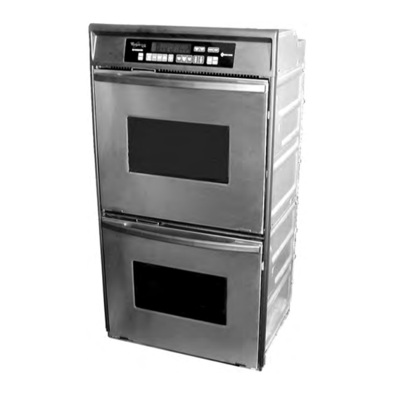
- Page 1 CONSUMER SERVICES TECHNICAL KR-30 EDUCATION GROUP PRESENTS ELECTRIC BUILT-IN DOUBLE OVEN JOB AID Part No. 8178007...
- Page 2 This Job Aid, “Whirlpool Electric Built-In Double Oven,” (Part No. 8178007), provides the technician with information on the installation and service of the Whirlpool Electric Built-In Double Oven. It is to be used as a training Job Aid and Service Manual. For specific information on the model being serviced, refer to the “Use and Care Guide,”...
-
Page 3: Table Of Contents
Table of Contents Page SPECIFICATIONS ........................1-1 INSTALLATION HIGHLIGHTS ....................2-1 Electrical Supply Requirements ..................2-1 Removing & Reinstalling The Oven Door ................2-3 PRODUCT OPERATION ......................3-1 Air Flow ..........................3-1 The Oven Shutdown Thermal Fuse & Control Panel Thermal Fuse ......... 3-2 The Oven Door Latch Assembly .................. - Page 4 Page WIRING DIAGRAMS & STRIP CIRCUITS ................7-1 Schematic Diagram 1 (Tech Sheet 4451887C) ..............7-1 Strip Circuits ........................7-2 Schematic Diagram 2 (Tech Sheet 4451888A) ..............7-4 Strip Circuits ........................7-5 Schematic Diagram 3 (Tech Sheet 4452022A) ..............7-7 Strip Circuits ........................
- Page 5 WHIRLPOOL MODEL & SERIAL NUMBER DESIGNATIONS MODEL NUMBER MODEL NUMBER INTERNATIONAL SALES IND. OR MARKETING CHANNEL IF PRESENT PRODUCT GROUP G = WHIRLPOOL GOLD R = ELECTRIC S = GAS PRODUCT IDENTIFICATION B = BUILT-IN M = BUILT-IN MICROWAVE COMBO...
- Page 6 MODEL & SERIAL NUMBER LABEL AND TECH SHEET LOCATIONS The Model/Serial Number label and Tech Sheet locations are shown below. Model & Serial Number Location Upper Oven Tech Sheet Location (Below Top Front Cover) - vi -...
- Page 7 IMPORTANT SAFETY INFORMATION Your safety and the safety of others is very important. Important safety messages have been provided in this Job Aid. Always read and obey all safety messages. This is the safety alert symbol. This symbol alerts you to hazards that can kill or hurt you and others. All safety messages will be preceded by the safety alert symbol and the word “WARNING.”...
- Page 8 — NOTES — - viii -...
-
Page 9: Specifications
SPECIFICATIONS Model Number GBD307PD GBD277PD RBD245PD Model Description Double Built-In Oven Double Built-In Oven Double Built-In Oven Size-Configuration 30" 27" 2 4 " Biscuit, White-On-White, Color Available Biscuit, Stainless Stainless Black Dimensions/Specifications Exterior Dimensions Overall Height (in) 51 1/8" 51 1/8"... - Page 10 Model Number RBD275PD RBD276PD RBD277PD Model Description Double Built-In Oven Double Built-In Oven Double Built-In Oven Size-Configuration 27" 27" 27" Biscuit, White-On- Color Available Black, White-On -White Black, White-On -White White, Black Dimensions/Specifications Exterior Dimensions Overall Height (in) 51 1/8" 51 1/8"...
- Page 11 Model Number RBD305PD RBD306PD RBD307PD Model Description Double Built-In Oven Double Built-In Oven Double Built-In Oven Size-Configuration 30" 30" 30" Biscuit, White-On- Black, Almond-On- Black, Almond-On-Almond, Color Available White, Black Almond, White-On-White White-On-White Dimensions/Specifications Exterior Dimensions Overall Height (in) 51 1/8" 51 1/8"...
- Page 12 — NOTES —...
-
Page 13: Installation Highlights
INSTALLATION HIGHLIGHTS ELECTRICAL SUPPLY REQUIREMENTS • The oven must be connected with copper WARNING wire only. • Wire sizes and connections must conform to Electrical Shock Hazard the requirements of the National Electrical • An electrical ground is required on this Code, ANSI/NFPA 70—latest edition*, and appliance. - Page 14 ELECTRICAL WIRING If local codes DO permit connecting the cabi- net-grounding conductor to a neutral junction WARNING box wire, perform steps 6 and 7. If local codes DO NOT permit connecting the Electrical Shock Hazard cabinet-grounding conductor to a neutral junc- tion box wire, or if you are connecting the •...
-
Page 15: Removing & Reinstalling The Oven Door
REMOVING & REINSTALLING THE OVEN DOOR Close the oven door as far as the two pins WARNING will allow. Grasp the sides of the door and lift the door Personal Injury Hazard until it stops, then pull the hinge hangers •... - Page 16 — NOTES —...
-
Page 17: Product Operation
PRODUCT OPERATION AIR FLOW Intake air is drawn into the oven at two loca- Air passes through the oven door by a combi- tions: through the control panel vent, (over the nation of natural and forced convection. Air latch assembly and the inner chassis top), and enters the door through the bottom slots, and through the side mounting rails (over the oven passes between the outer glass, and the angled... -
Page 18: The Oven Shutdown Thermal Fuse & Control Panel Thermal Fuse
THE OVEN SHUTDOWN THERMAL FUSE & CONTROL PANEL THERMAL FUSE • Control Panel Thermal Fuse — Pro- There are two thermal fuses on the oven. The tects the control panel area if the tem- thermal fuses operate as follows: perature exceeds 101˚C/214˚F. If the •... -
Page 19: The Oven Door Latch Assembly
THE OVEN DOOR LATCH ASSEMBLY The door latch solenoid operates on a 120-volt During the self-clean cycle, the control board dc pulse from the electronic control board. sends a 120-volt dc pulse to the solenoid When the solenoid plunger is retracted, the windings, which extends the plunger (pushes it oven door is in the “unlocked”... -
Page 20: How The Self-Clean Cycle Works
HOW THE SELF-CLEAN CYCLE WORKS The Self-Clean cycle uses high heat to burn The oven is preset for a 3- hour Self-Clean away soil and grease from inside the oven. cycle. However, you can adjust this cycle time During this cycle, the oven will get much hotter to between 2- and 4- hours. -
Page 21: Component Access
COMPONENT ACCESS This section instructs you on how to service each component inside the Electric Built-In Double Oven . The components and their locations are shown below. COMPONENT LOCATIONS Upper Blower Motor Power Supply Wiring Terminal Block Oven Control/Display Boards & Thermal Fuse Upper Door Latch Upper Broil Element Assembly... -
Page 22: Removing The Thermal Fuse, The Oven Control/Display Boards, And The Touch Panel Assembly
REMOVING THE THERMAL FUSE, THE OVEN CONTROL/ DISPLAY BOARDS, AND THE TOUCH PANEL ASSEMBLY Remove the screws from the oven control WARNING panel. Electrical Shock Hazard Disconnect power before servicing. Replace all panels before operating. Control Failure to do so could result in death or Panel electrical shock. - Page 23 To remove the oven control/display REASSEMBLY NOTE: When you reinstall the boards: oven control panel, use the following proce- dure (refer to the photos on the previous page, a) Remove the mounting screws. as necessary): b) Lift the ends of the locking arm and Reconnect the wiring to the control board disconnect the ribbon cable from its terminals.
-
Page 24: Removing The Power Supply Wiring Terminal Block And The Upper & Lower Blower Motors
REMOVING THE POWER SUPPLY WIRING TERMINAL BLOCK AND THE UPPER & LOWER BLOWER MOTORS Remove the screw from the conduit clamp WARNING and remove the clamp. Remove the 6 screws from the top rear Electrical Shock Hazard oven cabinet cover. Disconnect power before servicing. - Page 25 To remove the upper blower motor as- To remove the lower blower motor as- sembly: sembly: a) Remove the upper rear cover from the a) Remove the upper rear cover (see step oven (11 screws) . 7a) and the lower rear cover (8 screws). Upper Rear Cover Lower Rear Cover b) Disconnect the two wires from the lower...
-
Page 26: Removing The Upper & Lower Oven Door Latch Assembly
REMOVING THE UPPER & LOWER OVEN DOOR LATCH ASSEMBLY c) Remove the wires from the terminals of WARNING the solenoid and the two switches. d) Remove the two top screws from the Electrical Shock Hazard upper oven door latch assembly and remove the assembly. - Page 27 d) Raise the lower air duct cover and e) Remove the lower oven door latch as- remove the two screws from the lower sembly and disconnect the wires from oven door latch assembly. the two switches and the solenoid ter- minals.
-
Page 28: Removing An Oven Light & An Oven Temperature Sensor
REMOVING AN OVEN LIGHT & AN OVEN TEMPERATURE SENSOR b) Pry the socket ring and socket out of the WARNING oven cavity hole. Press in on the socket ring locking arms with a flat screwdriver Electrical Shock Hazard to release them. Disconnect power before servicing. -
Page 29: Removing A Broil Element
REMOVING A BROIL ELEMENT Remove the two front bracket screws and WARNING two rear bracket screws from the broil element. Electrical Shock Hazard Front Bracket Disconnect power before servicing. Screws Replace all panels before operating. Failure to do so could result in death or electrical shock. -
Page 30: Removing A Bake Element
REMOVING A BAKE ELEMENT Remove the two screws from the bake WARNING element bracket. Bracket Screws Electrical Shock Hazard Disconnect power before servicing. Replace all panels before operating. Failure to do so could result in death or electrical shock. CAUTION: When you work on the double oven, be careful when handling the sheet metal parts. -
Page 31: Removing An Oven Shutdown Thermal Fuse
REMOVING AN OVEN SHUTDOWN THERMAL FUSE WARNING Upper Oven Electrical Shock Hazard Shutdown Thermal Fuse Disconnect power before servicing. Replace all panels before operating. Failure to do so could result in death or electrical shock. CAUTION: When you work on the double oven, be careful when handling the sheet metal Lower Oven parts. -
Page 32: Removing The Convection Fan Motor Assembly
REMOVING THE CONVECTION FAN MOTOR ASSEMBLY sure to position the cover with the notch as WARNING shown when you reinstall it. Screw 1 of 3 Electrical Shock Hazard Disconnect power before servicing. Replace all panels before operating. Convection Failure to do so could result in death or Fan Motor electrical shock. - Page 33 Pull the oven out of its mounting location (see page 4-4, steps 1 through 3 for the procedure) so that you can access the rear covers. Remove the upper rear cover from the oven (see page 4-5, step 7a for the proce- Convection dure).
-
Page 34: Removing The Oven Door Glass, Hinges, & Handle
REMOVING THE OVEN DOOR GLASS, HINGES, & HANDLE To remove the outer door glass: CAUTION: When you work on the double oven, be careful when handling the sheet metal a) Remove the three outer glass holder parts. Sharp edges may be present, and you screws and two outer glass bracket can cut yourself if you are not careful. - Page 35 To remove the hinges and the inner d) Remove the insulation and the inner door glass: door glass. NOTE: You will have to remove both hinges to remove the inner door glass from the oven door liner. a) Lift either side of the door liner, remove Inner Door Glass the two door hinge screws, and remove the hinge.
-
Page 36: Removing The Oven Door Gasket
REMOVING THE OVEN DOOR GASKET Pull the ends of the gasket out of the liner CAUTION: When you work on the double holes and pull the clips out of their liner oven, be careful when handling the sheet metal holes. parts. -
Page 37: Component Testing
COMPONENT TESTING Before testing any of the components, perform • Check all connections before replacing com- the following checks: ponents, looking for broken or loose wires, failed terminals, or wires not pressed into • The most common cause for control failure is connectors far enough. -
Page 38: Convection Fan Motor
WARNING WARNING Electrical Shock Hazard Electrical Shock Hazard Disconnect power before servicing. Disconnect power before servicing. Replace all panels before operating. Replace all panels before operating. Failure to do so could result in death or Failure to do so could result in death or electrical shock. -
Page 39: Broil Element
WARNING WARNING Electrical Shock Hazard Electrical Shock Hazard Disconnect power before servicing. Disconnect power before servicing. Replace all panels before operating. Replace all panels before operating. Failure to do so could result in death or Failure to do so could result in death or electrical shock. -
Page 40: Oven Door Latch Assembly
WARNING WARNING Electrical Shock Hazard Electrical Shock Hazard Disconnect power before servicing. Disconnect power before servicing. Replace all panels before operating. Replace all panels before operating. Failure to do so could result in death or Failure to do so could result in death or electrical shock. -
Page 41: Diagnosis & Troubleshooting
DIAGNOSIS & TROUBLESHOOTING 3. Press the CLOCK touchpad until the cor- DIAGNOSTICS rect size is displayed. Before servicing, perform the following checks: 4. Press the CANCEL touchpad. • The most common cause for control failure is 5. Press and hold the LOWER OFF touchpad corrosion on connectors. -
Page 42: Failure/Error Display Codes-Tech Sheets 4451887C & 4451888A
• Upon replacement, immediately return the FAILURE/ERROR DISPLAY CODES old electronic oven control. Use the mailing TECH SHEETS 4451887C & label that is supplied with each new control. 4451888A • For double ovens, the failure code is dis- • Always disconnect the power to the unit played on the side of the display that corre- before touching the internal parts of the sponds to the oven with faulty part (upper... -
Page 43: Failure/Error Display Codes-Tech Sheet 4452022A
FAILURE/ERROR DISPLAY CODES TECH SHEET 4452022A... -
Page 44: Relay Logic Chart-Tech Sheets 4451887C & 4451888A
RELAY LOGIC CHART TECH SHEETS 4451887C & 4451888A RELAY LOGIC KEY = OFF = ON = CYCLING = ON OR OFF RELAY LOGIC CHART TECH SHEET 4452022A RELAY LOGIC KEY = OFF = ON = COOLING (MAX PERIOD = 60 SEC) = ON OR OFF = PULSED FOR 1/2 SEC... -
Page 45: Control Panel Test Locations-Tech Sheets 4451887C & 4451888A
CONTROL PANEL TEST LOCATIONS TECH SHEETS 4451887C & 4451888A LOWER OVEN UPPER OVEN FRONT/REAR FRONT/REAR COMPONENTS CHECK POINTS RESULTS COMPONENTS CHECK POINTS RESULTS SERVICEABLE SERVICEABLE Door Open = Door Open = P23-7 (BR/W) to Closed Circuit P23-2 (BR) to Closed Circuit Door Switch Front Door Switch... -
Page 46: Control Panel Test Locations-Tech Sheet 4452022A
CONTROL PANEL TEST LOCATIONS TECH SHEET 4452022A LOWER OVEN UPPER OVEN FRONT/REAR FRONT/REAR COMPONENTS CHECK POINTS RESULTS COMPONENTS CHECK POINTS RESULTS SERVICEABLE SERVICEABLE Door Open = Door Open = Closed Circuit P3-5 (BR/W) to Closed Circuit P3-3 (BR) to Door Switch Front Door Switch Front... -
Page 47: Wiring Diagrams & Strip Circuits
WIRING DIAGRAMS & STRIP CIRCUITS SCHEMATIC DIAGRAM 1 WIRE HARNESS SCHEMATIC GROUND (CHASSIS) AC DRIVE SOLENOID MOTOR NOTES: PLUG WITH FEMALE ENCLOSED RELAY COIL • When replacing the electronic control, CONNECTOR THERMISTOR t ° be sure to program the cavity size (see RECEPTACLE WITH RELAY OPERATED... -
Page 48: Strip Circuits
STRIP CIRCUITS BAKE & PREHEAT BAKE STANDARD CLEAN MODELS ONLY BAKE-2000W P18- 4 (P26-4) SELF-CLEAN MODELS ONLY BROIL-3000W OVEN P18- 1 SHUTDOWN (P26-2) THERMAL FUSE P24- 5 (P27-2) BLOWER BROIL OVEN SHUTDOWN THERMAL FUSE BROIL-3000W P18- 1 (P26-2) BLOWER P24- 5 (P27-2) CONVECTION &... - Page 49 CLEAN & PREHEAT CLEAN (SELF CLEAN MODELS ONLY) +5V SWITCH PULSE P23- 1 P25- 1 (Y/W) (P25-3) LATCH DOOR LOCK SOLENOID DRIVE 18VDC P25- 2 CIRCUIT (P25-4) (GY-W) (BR) DOOR ON LATCH ASSY SWITCH BAKE-2000W P23- 1 P18- 4 (P23-7) (TAN) (BR) (BR)
- Page 50 SCHEMATIC DIAGRAM 2 WIRE HARNESS SCHEMATIC GROUND (CHASSIS) AC DRIVE SOLENOID NOTES: MOTOR PLUG WITH FEMALE • When replacing the electronic control, ENCLOSED RELAY COIL CONNECTOR t ∞ THERMISTOR be sure to program the cavity size (see RECEPTACLE WITH RELAY OPERATED page 6-1).
-
Page 51: Strip Circuits
STRIP CIRCUITS BAKE & PREHEAT BAKE BAKE-2000W P18-4 (P26-4) BROIL-3000W P18-1 (P26-2) DOUBLE LINE BREAK RELAY BLOWER P24-5 (P27-2) BROIL BROIL-3000W P18-1 (P26-2) DOUBLE LINE BREAK RELAY BLOWER P24-5 (P27-2) CONVECTION & PREHEAT CONVECTION (CONVECTION MODELS, UPPER OVEN ONLY) CONV. FAN P24-6 BAKE-2000W P18-4... - Page 52 CLEAN & PREHEAT CLEAN (SELF CLEAN MODELS ONLY) P25-1 (Y/W) (P25-3) LATCH DRIVE CIRCUIT P25-2 (BR) (BR) (GY/W) (P25-4) BAKE-2000W P18-4 DOOR LOCK SOLENOID (P26-4) BROIL-3000W P18-1 (P26-2) DOUBLE LINE BREAK RELAY P24-5 (P27-2) BLOWER...
- Page 53 SCHEMATIC DIAGRAM 3 WIRE HARNESS SCHEMATIC GROUND (CHASSIS) AC DRIVE NOTES: SOLENOID MOTOR • When replacing the electronic control, PLUG WITH FEMALE ENCLOSED RELAY COIL be sure to attach the cavity select line CONNECTOR THERMISTOR t ∞ to the proper terminal (see “Cavity Size” RECEPTACLE WITH RELAY OPERATED...
-
Page 54: Strip Circuits
STRIP CIRCUITS BAKE & PREHEAT BAKE STANDARD CLEAN CAVITY ONLY BAKE-2000W P6-3 (P6-2) BROIL-3000W P5-1 P6-4 (P6-1) (P5-2) P4-6 P7-1 (P4-3) (GY/W) SELF CLEAN MODELS ONLY BLOWER BROIL BROIL-3000W P6-4 (P6-1 ) P5-1 P4-6 (P5-2 ) (P4-3 ) (GY/W) P7-1 BLOWER CONVECTION &... - Page 55 PREHEAT CLEAN (BELOW 600˚F) PULSE LOCK P4-7 RELAY (P4-4) UNLOCK BAKE-2000W P6-3 (P6-2) P5-1 BROIL-3000W (P5-2) P6-4 (P6-1) P4-6 (P4-3) (GY/W) P7-1 BLOWER...
-
Page 56: Tech Sheet / Model Number Usage Charts
GBD307PD-1 RBD305PD-12 RBD306PD-9 RBD345PD-6 GBD277PD-1 GBD277PD-7 GBD277PD-4 RBD305PD-6 GBD307PD-6 GBD307PD-4 TECH SHEET # WHERE USED RBD306PD-11 RBD276PD-8 4451888 Y GBD307PD-7 Y GBD307PD-4 RBD305PD-11 RBD245PD-8 Y GBD307PD-6 Y GBD307PD-3 GBD277PD-6 RBD275PD-8 Y GBD307PD-5 Y GB307PD-2 RBD276PD-11 RBD305PD-8 RBD275PD-11 PRD306PD-8 RBD245PD-11 GBD277PD-3... -
Page 57: Tech Tips
Use and Care Guide*: • APPLIANCE-HOUSEHOLD MAJOR, SERVICE & REPAIR (See Whirlpool Call the Whirlpool or Inglis Limited Con- Appliances or Authorized Whirlpool sumer Assistance Center telephone num- Service—Example: XYZ Service Co.) ber. Dial toll-free from anywhere: •... - Page 58 F. In Canada, travel or transportation expenses for customers who reside in remote areas. WHIRLPOOL CORPORATION AND INGLIS LIMITED SHALL NOT BE LIABLE FOR INCI- DENTAL OR CONSEQUENTIAL DAMAGES. Some states or provinces do not allow the exclu- sion or limitation of incidental or consequential damages, so this exclusion or limitation may not apply to you.
- Page 59 CORPORATION...