Table of Contents
Advertisement
Table of Contents
Section Code
Section
1
1
1
1
1
1
Moving the Machine
1
Leveling the Machine
1
1
1
1
2
Brake Lubrication
3
Brake Adjustment
4
Chain Tension Adjustment
5
6
7
8
9
10
11
12
13
14
15
16
Right Crank Arm and Sprocket Drive
Nautilus, Inc., www.NautilusInc.com, 5415 Centerpoint Parkway, Groveport, OH 43125 U.S.A. - Customer Service: North America (800) 605-3369, csnls@nautilus.com | outside U.S.
www.nautilusinternational.com | © 2013 Nautilus, Inc. | ® indicates trademarks registered in the United States. These marks may be registered in other nations or otherwise protected by
common law. Schwinn and the Schwinn logo are trademarks owned by or licensed to Nautilus, Inc. | ORIGINAL DOCUMENT - ENGLISH VERSION ONLY
8019183.070118.A
®
Schwinn
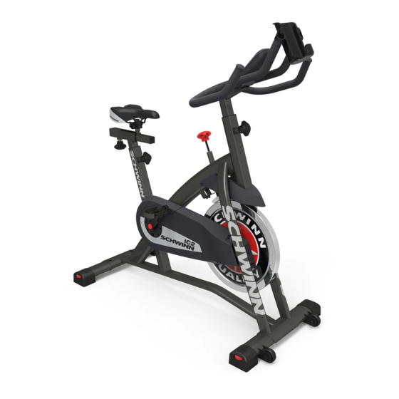
IC2 Bike
Service Manual
Page Number
2
3
3
4
4
6
6
7
8
9
10
11
11
14
16
20
20
22
24
27
29
32
35
39
41
45
52
60
Service Manual
004-4774.070118.C
Advertisement
Table of Contents

Related Manuals for Schwinn IC2


Summary of Contents for Schwinn IC2
-
Page 1: Table Of Contents
| © 2013 Nautilus, Inc. | ® indicates trademarks registered in the United States. These marks may be registered in other nations or otherwise protected by common law. Schwinn and the Schwinn logo are trademarks owned by or licensed to Nautilus, Inc. | ORIGINAL DOCUMENT - ENGLISH VERSION ONLY... -
Page 2: Important Safety Instructions
Nautilus, Inc., www.NautilusInc.com, 5415 Centerpoint Parkway, Groveport, OH 43125 U.S.A. - Customer Service: North America (800) 605-3369, csnls@nautilus.com | outside U.S. www.nautilusin- ternational.com | © 2013 Nautilus, Inc. | ® indicates trademarks registered in the United States. These marks may be registered in other nations or otherwise protected by common law. Schwinn and the Schwinn logo are trademarks owned by or licensed to Nautilus, Inc. -
Page 3: Safety Warning Labels And Serial Number
Safety Warning Labels and Serial Numbers 250lbs. (113kg). Serial number 250lbs. (113kg). Reading the Serial Number The instructions below show how to decode the information contained on the serial number. SERIAL NO. FORMAT AAAAAA - Product SKU VVV - Supplier code AAAAAAVVVYYWW9999 YY - Manufactured year WW - Manufactured week... -
Page 4: Specifications
Specifications Maximum User Weight 250 lbs. (113 kg) Power Requirements 2 AA batteries (LR6) Operational Voltage 1.0 - 3.3VDC 48.4” (123cm) 44.5” (113cm) 22.2” (56.4cm) Maintenance Read all maintenance instructions fully before you start any repair work. In some conditions, an assistant is necessary to do the necessary tasks. - Page 5 Chain Lubrication Do not apply lubricant when the chain is moving. Be sure to keep fingers clear of all pinch hazards. Remove the chain guard door and apply a small amount of lithium grease to the chain (C). Note: Use caution to avoid staining clothes or carpet. Replacing the Console Batteries The Console display will show “Batt”...
- Page 6 Moving the Bike To move the bike, carefully pull the Handlebars toward you while pushing the front of the bike downward. Push the bike to the desired location. NOTICE: Be careful when you move the machine. Abrupt motions can affect the computer operation.
-
Page 7: Troubleshooting
Troubleshooting Condition/Problem Things to Check Solution Console will not power up/turn Batteries Make sure batteries are installed correctly. If batteries are on/start correctly installed, replace with a set of new batteries. Check data cable integrity All wires in cable should be intact. If any are visibly crimped or cut, replace cable. -
Page 8: Console Service Mode
Console Service Mode Service Mode lets you set the units of measure to either English or Metric, see machine statistics and firmware version (for technician use only). When the Console is in Workout Mode or Pause Mode, push and hold down the button for 5 seconds to go into Service Mode. Note: Tap the button to move through the Service Mode Menu options. -
Page 9: Maintenance Parts Exploded View
Maintenance Parts Exploded View Your machine may differ. Use only as a guide. A Console Crank Arms Chain B Water Bottle Holder Pedals Speed Sensor Magnet C Handlebars Seat RPM Sensor D Brake/Resistance Knob Seat Post Sprocket Drive Brake Assembly M Adjustment Knobs Data Cable Chain Guard... -
Page 10: Replacement Procedure Skill Level
REPLACEMENT PROCEDURE SKILL LEVEL Level I : Low - very little mechanical knowledge or exposure. Level II : Intermediate - some experience with mechanical procedures Level III : Advanced - knowledgeable about mechanical procedures For instructions to replace the following parts, please refer to the Assembly Manual for your bike: •... - Page 11 ® on the Schwinn IC2 Bike 8003618.070118.B ® NOTICE: This document provides instructions for the lubrication of the Brake Pad on the Schwinn IC2 Bike. If you need assistance, please call Schwinn Customer Service at 1-800-605-3369. This icon means a potentially hazardous situation which, if not avoided, could result in death or serious injury. Read and understand all Warnings on this machine.
- Page 12 Disconnect the data cable from the console before you service this machine. Note: Your machine may not match the image. For reference only. 1. Using a #2 Phillips screwdriver, loosen and remove the hardware that attaches the Brake Cover to the Main Frame. Set the Brake cover and hardware safely aside for reassembly.
- Page 13 5. Saturate the Brake Pad felt (D) with silicone lubricant. Wipe off the excess lubricant to prevent drips and stains. 6. Reinstall the Brake Pad (B). NOTICE: Do not crimp the cable. 7. Reinstall the Brake Cover. NOTICE: Do not crimp the cable. Adjust the Resistance Knob (A) as necessary.
- Page 14 Replacement Procedure Skill Level: I ® on the Schwinn IC2 Bike 8003617.070118.B NOTICE: This document provides instructions for the adjustment of the Brake Assembly on the Schwinn ® IC2 Bike. If you need assistance, please call Schwinn Customer Service at 1-800-605-3369.
- Page 15 Disconnect the data cable from the console before you service this machine. Note: Your machine may not match the image. For reference only. Using a #2 Phillips screwdriver, loosen and remove the hardware that attaches the Brake Cover to the Main Frame. Set the Brake cover and hardware safely aside for reassembly.
- Page 16 Skill Level: II ® on the Schwinn IC2 Bike 8003619.070118.B NOTICE: This document provides instructions for the adjustment of the Drive Chain Tension on the Schwinn ® IC2 Bike. If you need assistance, please call Schwinn Customer Service at 1-800-605-3369.
- Page 17 Disconnect the data cable from the console before you service this machine. Note: Your machine may not match the image. For reference only. Loosen and remove the right Pedal. Set it safely aside for reassembly.
- Page 18 Carefully remove the Chain Guard Center from the Chain Guard Cover, and set it safely aside for reassembly. Remove the hardware that attaches the Chain Guard Cover to the Chain Guard Inside, and set it safely aside for reassembly. Carefully remove the Chain Guard Cover and set it safely aside for reassembly.
- Page 19 Use a 15 mm crescent wrench to hold the Axle Nut (B) on one side steady and loosen the Axle Nut on the opposite side with a 15 mm socket and wrench. Be sure to keep fingers clear of all pinch hazards. Check the tension: Find the point where the Drive Chain (A) is tightest during one revolution of the Crank (C).
-
Page 20: Pedals
Replacement Procedure Skill Level: I ® on the Schwinn IC2 Bike 8003620.070118.B NOTICE: This document provides instructions for the replacement of the Pedals on the Schwinn ® IC2 Bike. If you need assistance, please call Schwinn Customer Service at 1-800-605-3369. - Page 21 Disconnect the data cable from the console before you service this machine. Note: Your machine may not match the image. For reference only. 1. Loosen and remove the old Pedals. Discard the old Pedals. Note: The Left Pedal is reverse-threaded. Orientation is based from a seated position on the bike.
- Page 22 Skill Level: I ® on the Schwinn IC2 Bike 8003621.070118.B ® NOTICE: This document provides instructions for the replacement of the Console on the Schwinn IC2 Bike. If you need assistance, please call Schwinn ® Customer Service at 1-800-605-3369. This icon means a potentially hazardous situation which, if not avoided, could result in death or serious injury. Read and understand all Warnings on this machine.
-
Page 23: Console
Disconnect the data cable from the console before you service this machine. Note: Your machine may not match the image. For reference only. 1. Be sure the Data Cable is disconnected from the back of the Console. Remove the Console from the Console Bracket. Discard the old Console. -
Page 24: Handlebars And Handlebar Post
Skill Level: I ® on the Schwinn IC2 Bike 8003622.070118.B NOTICE: This document provides instructions for the replacement of the Handlebar and Handlebar Post on the Schwinn ® IC2 Bike. If you need assistance, please call Schwinn Customer Service at 1-800-605-3369. - Page 25 Disconnect the data cable from the console before you service this machine. Note: Your machine may not match the image. For reference only. 1. Be sure the Data Cable is disconnected from the back of the Console. Carefully remove the Console, and set it safely aside for reassembly.
- Page 26 3. Loosen and pull the Adjustment Knob (A) that holds the Handlebar Post in position in the Main Frame. Hold the Handlebar so that it does not fall. 4. Remove the Handlebar assembly from the Main Frame. NOTICE: Do not crimp the cable. 5.
-
Page 27: Brake Cover
® on the Schwinn IC2 Bike 8003623.070118.B ® NOTICE: This document provides instructions for the replacement of the Brake Cover on the Schwinn IC2 Bike. If you need assistance, please call Schwinn Customer Service at 1-800-605-3369. This icon means a potentially hazardous situation which, if not avoided, could result in death or serious injury. Read and understand all Warnings on this machine. - Page 28 Disconnect the data cable from the console before you service this machine. Note: Your machine may not match the image. For reference only. Loosen and remove the hardware that attaches the Brake Cover to the Main Frame. Set the hardware safely aside for reassembly.
-
Page 29: Brake Assembly And Resistance Knob Assembly
Replacement Procedure Skill Level: I Knob Assembly on the IC2 Bike 8003624.070118.B NOTICE: This document provides instructions for the replacement of the Brake Assembly and the Resistance Knob Assembly on the Schwinn ® IC2 Bike. If you need assistance, please call Schwinn Customer Service at 1-800-605-3369. - Page 30 Disconnect the data cable from the console before you service this machine. Note: Your machine may not match the image. For reference only. Keep the flywheel stable during this procedure. Do not turn the crank arms. Flywheel movement can pull fingers in and cause injury.
- Page 31 6. Remove the hex nut (D) at the end of the Resistance Knob rod (A1). 7. Loosen the Resistance Knob (A) to release the square nut (E) and spring (F) from the square mount (G) on the Frame. 8. Remove the old Resistance Knob assembly (A) and bushing (H) from the mount tube (I) on top of the Frame.
-
Page 32: Left Crank Arm
® on the Schwinn IC2 Bike 8003625.070118.B ® NOTICE: This document provides instructions for the replacement of the Left Crank Arm on the Schwinn IC2 Bike. If you need assistance, please call Schwinn Customer Service at 1-800-605-3369. This icon means a potentially hazardous situation which, if not avoided, could result in death or serious injury. Read and understand all Warnings on this machine. - Page 33 Disconnect the data cable from the console before you service this machine. Note: Your machine may not match the image. For reference only. Loosen and remove the Left Pedal. Set it safely aside for reassembly. Note: The Left Pedal is reverse-threaded. Orientation is based from a seated position on the bike.
- Page 34 Using a wrench and socket, remove the Hex Head Bolt (C) under the threaded Cap (B). Thread the Crank Puller into the Crank Arm (A). When the Crank Puller is in the correct position, only 1-2 threads on the outer portion (CP2) of the Crank Puller should show.
- Page 35 ® on the Schwinn IC2 Bike 8003626.070118.B ® NOTICE: This document provides instructions for the replacement of the Speed Sensor on the Schwinn IC2 Bike. If you need assistance, please call Schwinn Customer Service at 1-800-605-3369. This icon means a potentially hazardous situation which, if not avoided, could result in death or serious injury. Read and understand all Warnings on this machine.
-
Page 36: Speed Sensor
Disconnect the data cable from the console before you service this machine. Note: Your machine may not match the image. For reference only. Carefully remove the Chain Guard Door, and set it safely aside for reassembly. Disconnect the Speed Sensor cable (A) from the data cable (B) in the Frame. - Page 37 ® on the Schwinn IC2 Bike 8003627.070118.B ® NOTICE: This document provides instructions for the adjustment of the Drive Chain Tension on the Schwinn IC2 Bike. If you need assistance, please call Schwinn Customer Service at 1-800-605-3369. This icon means a potentially hazardous situation which, if not avoided, could result in death or serious injury. Read and understand all Warnings on this machine.
- Page 38 Disconnect the data cable from the console before you service this machine. Note: Your machine may not match the image. For reference only. Loosen and remove the Pedals. Set them safely aside for reassembly. Note: The Left Pedal is reverse-threaded. Orientation is based from a seated position on the bike.
-
Page 39: Chain Guard Covers
Loosen and remove the hardware that attaches the Chain Guard Cover to the Chain Guard Inside. Carefully remove the Chain Guard Cover and discard it. Disconnect the Speed Sensor cable (A) from the data cable (B) in the Frame. NOTICE: Do not crimp the cable. Remove the hardware (C) that attaches the Speed Sensor (D) to the Main Frame. - Page 40 Loosen and remove the hardware that attaches the Chain Guard Inside to the Main Frame. Set the hardware safely aside. Carefully lift and slide the Chain Guard Inside forward to disengage from the axles, then move it toward the rear of the bike.
- Page 41 Skill Level: II ® on the Schwinn IC2 Bike 8003628.070118.B NOTICE: This document provides instructions for the replacement of the Flywheel Retainer Clips on the Schwinn ® IC2 Bike. If you need assistance, please call Schwinn Customer Service at 1-800-605-3369.
- Page 42 NOTICE: At the end of this procedure, make sure that the Drive Chain tension is correct. Refer to the “Adjust the Chain Tension” procedure. Disconnect the data cable from the console before you service this machine. Note: Your machine may not match the image. For reference only. Loosen and remove the right Pedal.
- Page 43 Remove the hardware that attaches the Chain Guard Cover to the Chain Guard Inside, and set it safely aside for reassembly. Carefully remove the Chain Guard Cover and set it safely aside for reassembly. Mark the position of the Flywheel Retainer Clips (A) on the flywheel brackets (B) on the Frame.
-
Page 44: Retainer Clips
To loosen the Flywheel hardware, use a 15 mm crescent wrench to hold the Axle Nut (D) on one side steady and loosen the Axle Nut on the opposite side with a 15 mm socket and wrench. Remove the Axle Nuts from the Flywheel axle (E). Set the hardware safely aside for reassembly. -
Page 45: Drive Chain
® on the Schwinn IC2 Bike 8003629.070118.B ® NOTICE: This document provides instructions for the replacement of the Drive Chain on the Schwinn IC2 Bike. If you need assistance, please call Schwinn Customer Service at 1-800-605-3369. This icon means a potentially hazardous situation which, if not avoided, could result in death or serious injury. Read and understand all Warnings on this machine. - Page 46 NOTICE: At the end of this procedure, make sure that the Drive Chain tension is correct. Refer to the “Adjust the Chain Tension” procedure. Disconnect the data cable from the console before you service this machine. Note: Your machine may not match the image. For reference only. Loosen and remove the Pedals.
- Page 47 Loosen and remove the hardware that attaches the Chain Guard Cover to the Chain Guard Inside. Carefully remove the Chain Guard Cover and set it safely aside for reassembly. Disconnect the Speed Sensor cable (S1) from the data cable (S2) in the Frame. NOTICE: Do not crimp the cable.
- Page 48 Loosen and remove the hardware that attaches the Chain Guard Inside to the Main Frame. Set the hardware safely aside. Carefully lift and slide the Chain Guard Inside forward to disengage from the axles, then move it toward the rear of the bike.
- Page 49 Mark the position of the Flywheel Retainer Clips (A) on the flywheel brackets (B) on the Frame. Record the number of threads showing on the Hex Head Bolt (C) that attaches each Flywheel Retainer Clip to the Frame. 10. To loosen the Flywheel hardware, use a 15 mm crescent wrench to hold the Axle Nut (D) on one side steady and loosen the Axle Nut on the opposite side with a 15 mm socket and wrench.
- Page 50 11. Loosen the Hex Head Bolt (C) that attaches each Flywheel Retainer Clip (A) to the Frame. Remove the Hex Head Bolts, Flywheel Retainer Clips and Nuts (F) from the Frame. Keep the hardware safely aside for reassembly. Loosen the Resistance Knob (R) to the minimum resistance setting. 12.
- Page 51 15. Installation is the reverse procedure. NOTICE: Install the Flywheel Retainer Clips (A) at the position that you recorded in step 9. Make sure the Flywheel (G) can turn easily. NOTICE: Do not crimp any cables. Note: Before closing the Chain Guard Door (1), verify that the Speed Sensor (S4) and Speed Sensor Magnet (S5) on the Sprocket Drive (K) do not touch.
-
Page 52: Flywheel Assembly
Replacement Procedure Skill Level: III ® on the Schwinn IC2 Bike 8003630.070118.B NOTICE: This document provides instructions for the replacement of the Flywheel Assembly on the Schwinn ® IC2 Bike. If you need assistance, please call Schwinn Customer Service at 1-800-605-3369. - Page 53 NOTICE: At the end of this procedure, make sure that the Drive Chain tension is correct. Refer to the “Adjust the Chain Tension” procedure. Disconnect the data cable from the console before you service this machine. Note: Your machine may not match the image. For reference only. Loosen and remove the Pedals.
- Page 54 4. Loosen the Resistance Knob (R) to the minimum resistance setting. 5. Using a 3mm hex key, remove the hardware (1a) that attaches the Brake Assembly (1) to the Frame Mount (2). Set the hardware safely aside for reassembly. Note: The nuts may turn along with the screws when you try to loosen the hardware (1a).
- Page 55 Loosen and remove the hardware that attaches the Chain Guard Cover to the Chain Guard Inside. Carefully remove the Chain Guard Cover and set it safely aside for reassembly. 10. Disconnect the Speed Sensor cable (S1) from the data cable (S2) in the Frame.
- Page 56 12. Loosen and remove the hardware that attaches the Chain Guard Inside to the Main Frame. Set the hardware safely aside. 13. Carefully lift and slide the Chain Guard Inside forward to disengage from the axles, then move it toward the rear of the bike.
- Page 57 14. Mark the position of the Flywheel Retainer Clips (A) on the flywheel brackets (B) on the Frame. Record the number of threads showing on the Hex Head Bolt (C) that attaches each Flywheel Retainer Clip to the Frame. 15. To loosen the Flywheel hardware, use a 15 mm crescent wrench to hold the Axle Nut (D) on one side steady and loosen the Axle Nut on the opposite side with a 15 mm socket and wrench.
- Page 58 16. Loosen the Hex Head Bolt (C) that attaches each Flywheel Retainer Clip (A) to the Frame. Remove the Hex Head Bolts, Flywheel Retainer Clips and Nuts (F) from the Frame. Keep the hardware safely aside for reassembly. 17. Carefully move the Flywheel (G) to the opening in the flywheel brackets (B).
- Page 59 19. Installation is the reverse procedure. NOTICE: Install the Flywheel Retainer Clips (A) at the position that you recorded in step 14. Make sure the Flywheel (G) can turn easily. NOTICE: Do not crimp any cables. Note: Before closing the Chain Guard Door (3), verify that the Speed Sensor (S4) and Speed Sensor Magnet (S5) on the Sprocket Drive (K) do not touch.
- Page 60 ® on the Schwinn IC2 Bike 8003631.070118.B ® NOTICE: This document provides instructions for the replacement of the Right Crank Arm/Sprocket Drive Assembly on the Schwinn IC2 Bike. If you need assistance, please call Schwinn Customer Service at 1-800-605-3369. This icon means a potentially hazardous situation which, if not avoided, could result in death or serious injury. Read and understand all Warnings on this machine.
- Page 61 NOTICE: At the end of this procedure, make sure that the Drive Chain tension is correct. Refer to the “Adjust the Chain Tension” procedure. Disconnect the data cable from the console before you service this machine. Note: Your machine may not match the image. For reference only. Loosen and remove the Pedals.
- Page 62 Loosen and remove the hardware that attaches the Chain Guard Cover to the Chain Guard Inside. Carefully remove the Chain Guard Cover and set it safely aside for reassembly. Disconnect the Speed Sensor cable (S1) from the data cable (S2) in the Frame. NOTICE: Do not crimp the cable.
- Page 63 Loosen and remove the hardware that attaches the Chain Guard Inside to the Main Frame. Set the hardware safely aside. Carefully lift and slide the Chain Guard Inside forward to disengage from the axles, then move it toward the rear of the bike.
- Page 64 Mark the position of the Flywheel Retainer Clips (A) on the flywheel brackets (B) on the Frame. Record the number of threads showing on the Hex Head Bolt (C) that attaches each Flywheel Retainer Clip to the Frame. 10. To loosen the Flywheel hardware, use a 15 mm crescent wrench to hold the Axle Nut (D) on one side steady and loosen the Axle Nut on the opposite side with a 15 mm socket and wrench.
- Page 65 11. Loosen the Hex Head Bolt (C) that attaches each Flywheel Retainer Clip (A) to the Frame. Remove the Hex Head Bolts, Flywheel Retainer Clips and Nuts (F) from the Frame. Keep the hardware safely aside for reassembly. 12. Carefully move the Flywheel (G) to the opening in the flywheel brackets (B).
- Page 66 14. Using a flathead screwdriver, remove the threaded Cap (L) from the Sprocket Drive/Crank Arm assembly (K). 15. Using a wrench and socket, remove the Hex Head Bolt (M) under the threaded Cap (L). 16. Thread the Crank Puller into the Crank Arm (K). When the Crank Puller is in the correct position, only 1-2 threads on the outer portion (CP2) of the Crank Puller should show.
Need help?
Do you have a question about the IC2 and is the answer not in the manual?
Questions and answers