Table of Contents
Advertisement
Quick Links
GE Healthcare
Module Frames and Modules
Technical Manual
CAUTION: U.S. Federal law restricts this device to sale by or on the order of a licensed medical practitioner.
Outside the USA, check local laws for any restriction that may apply.
All specifications subject to change without notice.
English
Order code
#2062973-004 paper
October 5, 2016
© 2013 - 2016 General Electric Company. All rights reserved.
Advertisement
Chapters
Table of Contents
Troubleshooting

Related Manuals for GE HEALTHCARE E-PSMP


Summary of Contents for GE HEALTHCARE E-PSMP
- Page 1 GE Healthcare Module Frames and Modules Technical Manual CAUTION: U.S. Federal law restricts this device to sale by or on the order of a licensed medical practitioner. Outside the USA, check local laws for any restriction that may apply. All specifications subject to change without notice.
- Page 3 #2062978-002 DVD 510(k) #2062973-004 paper Description About this manual PRESTN Modules, E-PRESTN, E-RESTN, E-PRETN Patient Side Modules, E-PSM, E-PSMP Rev.01 PiCCO Module, E-PiCCO Cardiac Output Modules E-COP and E-COPSv Rev. 01 Pressure Module, E-P, Pressure Temp Module, E-PT, Dual Pressure Module, E-PP...
- Page 4 Module Frames and Modules For your notes: 2062973-004...
- Page 5 Table of contents Table of contents About this manual Intended use of the manual ............1-1 Intended audience of the manual.
- Page 6 Module Frames and Modules 1 - ii 2062973-004...
-
Page 7: About This Manual
About this manual About this manual 1.1 Intended use of the manual This Module Frames and Modules Technical Manual must be used in conjunction with the CARESCAPE modular monitor’s technical manual for important safety information. This manual contains instructions necessary to perform planned and corrective maintenance to the parameter modules and module frames. - Page 8 Module Frames and Modules − Regular maintenance, irrespective of usage, is essential to ensure that the equipment will always be functional when required. 1.5.1 Equipment identification Every GE device has a unique serial number for identification. A sample of the information found on a serial number label is shown below.
- Page 9 F5 and F7. Figure 1 Device plate location, Patient Data Module and module frames The device plate is located beside the docking rails of the E-PSM and E-PSMP modules and on the left side of the plug-in E-modules. Figure 2 Device plate location, E-PSM and E-modules 1.5.4 Access to Webmin...
- Page 10 Module Frames and Modules For your notes: 1 - 4 2062973-004...
- Page 11 Hemodynamic Modules E-PRESTN, E-RESTN, E-PRETN (Rev. 00) E-PSMP, E-PSM (Rev. 01) Technical Manual...
-
Page 13: Table Of Contents
Table of contents Table of contents Product overview Introduction ............... . 2-1 Measurement principle. - Page 14 Patient Side Modules, E-PSM, E-PSMP (Rev. 01) ........
-
Page 15: Product Overview
Hemodynamic Modules E-PRESTN, E-RESTN, E-PRETN, E-PSMP, E-PSM Product overview 1.1 Introduction This document provides information for the maintenance and service of the Patient Side Modules E-PSMP and E-PSM, and the double-width plug-in hemodynamic modules, E-PRETN, E-PRESTN and E-RESTN. These modules provide general hemodynamic parameters. Figure 1 Patient Side Module, E-PSMP, and Hemodynamic Module, E-PRESTN. -
Page 16: Measurement Principle
Module Frames and Modules Safety symbol for the E-PRESTN, E-RESTN, and E-PRETN modules: When displayed on the module, indicates that protection against cardiac defibrillator discharge is due in part to the accessories for pulse oximetry (SpO temperature (T) and invasive pressure (P) measurement. 1.2 Measurement principle 1.2.1 ECG Electrocardiography analyzes the electrical activity of the heart by measuring the electrical... -
Page 17: Pulse Oximetry
Hemodynamic Modules E-PRESTN, E-RESTN, E-PRETN, E-PSMP, E-PSM These modules use the constant current method. The NTC-resistor is connected in series with a normal resistor and a constant voltage is applied across them. The temperature dependent voltage can be detected at the junction of the resistors, thus producing the temperature signal from the patient. - Page 18 Module Frames and Modules Pulse rate The pulse rate calculation is done by peak detection of the plethysmographic pulse wave. The signals are filtered to reduce noise and checked to separate artifacts. Figure 2 Absorption of infrared light in the finger SpO 2 sensor connector IRED Em itter...
-
Page 19: Nibp
Hemodynamic Modules E-PRESTN, E-RESTN, E-PRETN, E-PSMP, E-PSM The standard probe is a finger clamp probe which contains the light source LEDs in one half and the photodiode detector in the other half. Different kinds of probes are available from GE Healthcare. -
Page 20: Main Components
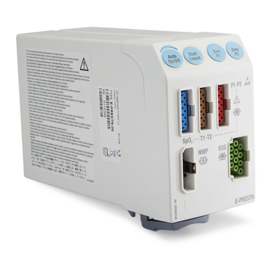
Module Frames and Modules 1.3 Main components 1.3.1 Controls and connectors Figure 4 Front and back panel connectors of E-PRESTN module Module keys Module Description Auto On/Off E-PRESTN, E-PRETN, E-RESTN Starts and stops autocycling NIBP measurements Start Cancel Starts a single NIBP measurement, and cancels any measurement. - Page 21 Hemodynamic Modules E-PRESTN, E-RESTN, E-PRETN, E-PSMP, E-PSM Figure 5 Front panel and connectors of E-PSMP module and the back of the module Module keys Module Description Auto On/Off E-PSM, E-PSMP Starts and stops autocycling NIBP measurements Start Cancel Starts a single NIBP measurement, and cancels any measurement.
-
Page 22: E-Psm(P) And E-(P)Re(S)Tn Modules
Module Frames and Modules 1.3.2 E-PSM(P) and E-(P)RE(S)TN modules The modules contain three main PC boards, the STP board, the ECG board, and the NIBP board. Each of these boards contain a processor and software in the processor flash memory. The boards produce their own supply voltages from the Vmod 13.8-16 V line that is available via the module bus connector. -
Page 23: Ecg Board
Hemodynamic Modules E-PRESTN, E-RESTN, E-PRETN, E-PSMP, E-PSM 1.3.3 ECG board The ECG measurement consists of the functions shown in the figure6. All functions are located in the ECG board except the ECG input unit. Figure 6 ECG measurement block diagram... - Page 24 Module Frames and Modules ECG amplifiers and baseline restoration The function of the ECG amplifiers and baseline restoration is to amplify the signal and to restore the baseline of the signal in the middle of the display after the change of the signal level, e.g.
-
Page 25: Stp Board
Hemodynamic Modules E-PRESTN, E-RESTN, E-PRETN, E-PSMP, E-PSM In diagnostic mode the upper frequency is 150 Hz and it is limited by software. 1.3.4 STP board Figure 7 STP board block diagram Microprocessor unit The CPU is a 16 bit H8/3052 single-chip microcomputer. It contains 128 kbytes of flash memory and 4 kbytes of RAM. - Page 26 Module Frames and Modules Temperature measurement unit The NTC-resistor value in the probe depends on the patient’s temperature. It is measured with the following principle. The constant current source supplies about 38 μA current through the temperature sensor (400 series NTC resistor). The constant current causes a voltage over the temperature sensor (NTC resistor).
- Page 27 Hemodynamic Modules E-PRESTN, E-RESTN, E-PRETN, E-PSMP, E-PSM Figure 9 Pressure measurement principle Pulse oximetry measurement section LED control signals The D/A converters of the microcontroller on the STP board set the LED intensity adjustment values for the infrared and red LEDs of the SpO probe.
- Page 28 Module Frames and Modules Figure 10 Pulse oximetry measurement block diagram Red and infrared channel separation It is possible to multiplex the detector signal to four different channels depending on the content of the signal. The detector signal must at least multiplex into infrared and red signals. Other channels are e.g.
- Page 29 Hemodynamic Modules E-PRESTN, E-RESTN, E-PRETN, E-PSMP, E-PSM Figure 11 Serial communication of E-PSM(P) and E-(P)RE(S)TN module Signals and isolation barrier The communication signals transfer over the isolation barrier by using high isolation voltage (6kV) opto isolators. Power supply section The power for the electronics on the floating part of the STP and the ECG boards is made on each board with the switching power supplies connected to a high voltage isolated transformer.
-
Page 30: Nibp Board
Module Frames and Modules 1.3.5 NIBP board Figure 12 NIBP board functional block diagram Signal processing Two signals from the pressure transducers are amplified and sent to the A/D converter. After the converter, digitized signals are sent to the microprocessor for data processing. The NIBP board is controlled with an H8/3052 microprocessor at 16 MHz oscillator frequency. - Page 31 Hemodynamic Modules E-PRESTN, E-RESTN, E-PRETN, E-PSMP, E-PSM Software control The software controls valves and a pump. In addition to the individual on/off signals for each component there is a common power switch for the valves and the pump that can be used at pump/valve failures.
- Page 32 Module Frames and Modules Figure 14 E-PSMP pneumatics The modules have the following pneumatics parts: NIBP air filter for preventing dust and other parts from entering the air pump and the valves. Air pump for pumping the measuring pressure of the cuff.
- Page 33 Hemodynamic Modules E-PRESTN, E-RESTN, E-PRETN, E-PSMP, E-PSM Figure 15 NIBP pneumatics diagram Power supply section of the NIBP board All connections are established via a module bus connector. The module needs a +15 V power supply to operate. The supply voltage (+15V) is generated in the power supply section of the monitor.
-
Page 34: Configuration
Configuration 2.1 STP/TP /ST-Settings The E-PRESTN, E-PRETN, E-RESTN, E-PSM and E-PSMP modules include the STP board and software. The STP/TP/ST setting defines the parameter set the module is capable of measuring. This setting is stored into the permanent memory of the module. - Page 35 Hemodynamic Modules E-PRESTN, E-RESTN, E-PRETN, E-PSMP, E-PSM Activation and verification The new STP/TP/ST setting will come into effect only after the module is restarted. To restart the module: Disconnect the configured module and wait for approximately 5 seconds. Reconnect the configured module.
-
Page 36: Maintenance And Checkout
6.2.2. Replacing the NIBP air filter (E-PRESTN, E-PRETN and E-RESTN) and section 6.3.4. Replacing the NIBP air filter (E-PSMP and E-PSM). 3.2 Visual inspections Detach the module from the module slot and check: • that the front cover is intact •... -
Page 37: Electrical Safety Tests
Hemodynamic Modules E-PRESTN, E-RESTN, E-PRETN, E-PSMP, E-PSM • the module and applied parts are clean The cleaning precautions, cleaning requirements, cleaning procedures, and recommended cleaning solutions for the monitor are described in the patient monitor’s user’s manual. For details about cleaning, disinfecting and sterilizing the accessories, see the instructions for use in the accessory package. - Page 38 Module Frames and Modules NOTE: The diameter of a a rigid cylinder should be correct for the cuff selected. A too small or big cylinder may impact NIBP calibration check result. See CARESCAPE monitor’s user's manual for details about Cuff Positioning. −...
- Page 39 Hemodynamic Modules E-PRESTN, E-RESTN, E-PRETN, E-PSMP, E-PSM Monitor configuration ECG: Configure the ECG1, ECG2 and ECG3 waveform fields to the monitor screen with adequate priority. Select the Setup tab in the ECG menu and configure: ECG1 Lead: II ECG2 lead: V1...
- Page 40 Module Frames and Modules Select the P1 tab in the Invasive Pressure menu and configure: Label: P1 Scale (mmHg): 0-200 mmHg Parameter Format: Sys/Dia (Mean) Select the P2 tab in the Invasive Pressure menu and configure: Label: P2 Scale (mmHg): 0-200 mmHg Parameter Format: Sys/Dia (Mean) Temperature: Configure the T1 and T2 parameter windows to the monitor screen with adequate...
-
Page 41: Ecg Tests
Hemodynamic Modules E-PRESTN, E-RESTN, E-PRETN, E-PSMP, E-PSM InvBP outputs: " 0 mmHg static pressure" or "atmosphere" Temperature • Configure the simulator’s temperature channels as follows: ° ° C /98.6 Temperature 3.4.2 ECG tests Normal Sinus Rhythm Check that the monitor displays the ECG leads II, V1 & aVL and the waveforms are noise-free. -
Page 42: Invasive Pressure Tests
Module Frames and Modules 3.4.4 Invasive pressure tests Perform the following test steps to both to the P1 and to the P2 invasive pressure channels. NOTE: The ‘x’ in the PX refers to the invasive pressure channel being tested. Zeroing Ensure that the simulator InvBP output channel is configured to "... -
Page 43: Nibp Tests
Hemodynamic Modules E-PRESTN, E-RESTN, E-PRETN, E-PSMP, E-PSM Check that the SpO2 reading in the parameter window is between 90-100 and the plethysmographic waveform appears on the screen. NOTE: You can verify the functionality of a pulse oximeter probe and monitor with a functional SpO2 tester, but you cannot evaluate their accuracy with such a device. -
Page 44: Test Completion
Module Frames and Modules 16. NIBP calibration Calibrate the Non-invasive blood pressure (NIBP) channel according to the instructions in 4.3. NIBP calibration” section. 17. NIBP hose detection Disconnect the calibration setup Attach an infant NIBP cuff hose without cuff identification to the module and check that the module identifies the hose by showing a 'Select inflation limits' message in the NIBP field. -
Page 45: Calibration And Adjustments
Hemodynamic Modules E-PRESTN, E-RESTN, E-PRETN, E-PSMP, E-PSM Calibration and adjustments 4.1 Invasive pressure calibration Invasive pressure calibration shall be performed: • whenever the pressure transducer in use is replaced with a new type of transducer • if the invasive pressure calibration check in section “3.4.4” failed. -
Page 46: Procedure
Module Frames and Modules 4.1.2 Procedure Select Monitor Setup > Service Calibrations. Enter the User Name and the Password and press Enter to get into the Calibrations menu. Select Invasive Pressures. Select the tab of the invasive pressure channel, P1 or P2, you want to calibrate. Prepare the transducer for the zeroing by opening the dome stopcock to room air. -
Page 47: Temperature Calibration
Hemodynamic Modules E-PRESTN, E-RESTN, E-PRETN, E-PSMP, E-PSM NOTE: 'Calibration Error' message is shown, if you do not start inflating the pressure within 45 seconds after the automatic zeroing is completed, or if the calibration fails. 4.2 Temperature calibration Temperature calibration shall be performed: •... -
Page 48: Nibp Calibration
Module Frames and Modules Select Calibrate to start the calibration procedure. Wait until 'Plug in 25 °C' message is shown. Plug in the temperature calibration plug labelled with TEMP 25°C/77°F to the dual temperature adapter cable connector T1 (=temperature channel T1) or T2 (=temperature channel T2). Wait until the value is shown in the Temperature °C field and select Confirm. -
Page 49: Setup
Hemodynamic Modules E-PRESTN, E-RESTN, E-PRETN, E-PSMP, E-PSM 4.3.1 Setup Required tools − A pressure manometer with either an integrated or a separate pressure pump − Adult NIBP hose (with cuff id) − Adult NIBP cuff − a rigid cylinder or pipe −... - Page 50 Module Frames and Modules Set the NIBP calibration protection "Off" to enable NIBP calibration: • Press the module buttons Auto On/Off and Start Cancel simultaneously for 3 seconds to activate the Protection drop-down menu. • Select Protection "Off". Select Start to start Calibration. NIBP calibration sequence starts with automatic zeroing. Wait until the message 'Zeroing' is replaced by a message 'Zero Ok'.
- Page 51 Hemodynamic Modules E-PRESTN, E-RESTN, E-PRETN, E-PSMP, E-PSM Auto On/Off Start Cancel Press the module buttons simultaneously for 3 seconds to inactivate the Protection drop-down menu. NOTE: Calibration protection is set automatically "On" after 30 seconds of inactivity, after the NIBP calibration menu is closed, and after zeroing or calibration failure. Set the calibration protection "Off"...
-
Page 52: Troubleshooting
Module Frames and Modules Troubleshooting The problems and solutions in this chapter represent only a few of the faults that you may encounter and are not intended to cover every possible problem that may occur. This chapter focuses on troubleshooting technical problems. Refer also to the troubleshooting hints on the patient monitor’s user’s manual for troubleshooting monitoring problems, performance issues and clinical configuration issues. -
Page 53: Service Interface
Service logs are used for recording different system events, errors and alarms to help troubleshoot equipment problems. The following service logs may contain information related to the E-PRESTN, E-PRETN, E-RESTN, E-PSMP and E-PSM module. • Clinical Log is used for recording different system events, messages, clinical alarms, user interactions and internal communication events. -
Page 54: Messages
Module Frames and Modules To view a log file in Webmin: Log on to the Webmin application. Select the Diagnostics tab. Select View Logs. Select one of the log files for viewing. To download a log file to an external media: Log on to the Webmin application. - Page 55 Hemodynamic Modules E-PRESTN, E-RESTN, E-PRETN, E-PSMP, E-PSM Message Location Possible causes Possible solutions Artifact Motion artifact. Check the patient status. Check the electrodes. Unreliable HR calculation or Ensure that the patient is not distorted waveform, possibly shivering. during defibrillation or because Incorrect ECG filter.
-
Page 56: Impedance Respiration
Module Frames and Modules 5.4.2 Impedance respiration The messages below appear in the Resp parameter window (PW), ImpResp waveform field (WF) or the message field (MF). Message Location Possible causes Possible solutions Measurement off WF, PW ECG cable is disconnected. Connect the ECG cable. - Page 57 Hemodynamic Modules E-PRESTN, E-RESTN, E-PRETN, E-PSMP, E-PSM Message Location Possible causes Possible solutions Px under range Measured pressure is under -40 The measurement range is mmHg /-5 kPa lower between -40 mmHg and 320 <-40 mmHg' or '<-5 kPa specification limit.
-
Page 58: Temperature
Module Frames and Modules 5.4.4 Temperature The messages below appear in the Temperature parameter window (PW) or the message field (MF). Message Location Possible causes Possible solutions Identical temperature Identical temperature modules. Remove one of the modules module The module detects the same providing identical temperature temperature channel from two or channel. -
Page 59: Nibp
Hemodynamic Modules E-PRESTN, E-RESTN, E-PRETN, E-PSMP, E-PSM 5.4.6 NIBP The messages below appear in the NIBP parameter window (PW) or the message field (MF). Message Location Possible causes Possible solutions NIBP measurement The module is disconnected. Reconnect the module. removed NIBP cuff occlusion 1. - Page 60 Module Frames and Modules Message Location Possible causes Possible solutions NIBP air leakage 1. Hose or cuff leaking. Reasons: 1. Replace cuff Air leakage cuff damaged Replace cuff. cuff connector damaged Replace cuff connector (if the fault is in hose connector). O-ring damaged or missing Replace O-ring.
- Page 61 Hemodynamic Modules E-PRESTN, E-RESTN, E-PRETN, E-PSMP, E-PSM Message Location Possible causes Possible solutions Weak pulsation All invisible reasons, weak Requires immediate correction oscillation, or poor performance i.e. changed cuff position etc. like algorithm etc. technically related reasons. Weak or unstable oscillation...
- Page 62 Module Frames and Modules Message Location Possible causes Possible solutions Call Service: Error x NIBP hardware error. Contact Message stays on screen until the authorized service personnel. problem is fixed. Replace module and contact authorized service x = error number 1 - 99. personnel.
-
Page 63: Troubleshooting Chart
Hemodynamic Modules E-PRESTN, E-RESTN, E-PRETN, E-PSMP, E-PSM 5.5 Troubleshooting chart 5.5.1 Invasive Pressure Problem Possible causes Possible solutions Abnormally low pressure. Transducer wrongly Check mid-heart level and positioned. reposition transducer. No pressure. Defective transducer. Check or replace transducer. Module not connected. -
Page 64: Disassembly And Reassembly
Module Frames and Modules Disassembly and reassembly 6.1 Disassembly guidelines Field service of the module is limited to replacing faulty circuit boards and mechanical parts only (see chapter 7. Service parts for details). WARNING Attempting a field repair on a PCB or a factory sealed component or assembly could jeopardize the safe and effective operation of the module, and void the warranty. -
Page 65: Required Tools
Hemodynamic Modules E-PRESTN, E-RESTN, E-PRETN, E-PSMP, E-PSM 6.1.3 Required tools antistatic wristband pincers flat blade screwdriver torx screwdrivers; T6, T8 and T10 6.2 Disassembling and reassembling procedure, E-PRESTN, E-PRETN, E-RESTN In case you are replacing either the Front chassis unit or the manifold, start by removing the Module Front Cover from the module by releasing the snaps that hold the front cover to the front chassis. - Page 66 Module Frames and Modules 3. Removing the ECG board Remove the four screws (T6) holding the insulator cover and lift the cover up. NOTE: When reassembling, push the ECG board a little to ensure that the insulator plates are correctly reassembled. Guide the upper plate inside the lips of the lower plate.
- Page 67 Hemodynamic Modules E-PRESTN, E-RESTN, E-PRETN, E-PSMP, E-PSM Disconnect the ECG input flex connector from the ECG board. Be careful not to damage the flex. 4. Removing the STP board. Lift the ECG-STP board insulator plate up. Disconnect the module bus connector from the STP board.
- Page 68 Module Frames and Modules 5. Removing the NIBP board: Lift the STP-NIBP board insulator plate up. Flip the module over and disconnect the hoses (2 pcs) coming from the manifold. NOTE: Note the positions of the hoses; mark them if necessary to ensure they are replaced correctly.
- Page 69 Hemodynamic Modules E-PRESTN, E-RESTN, E-PRETN, E-PSMP, E-PSM 7. Removing the Front Chassis Unit: Carefully push/ pull the STP input flex connector through the ferrites to the other side of the frame. The ferrites should stay in place, if not, remember to reassemble them.
- Page 70 Module Frames and Modules 8. Removing the manifold: Open the connector lock from the NIBP flex board and disconnect the membrane keyboard flex. Remove the two (T6) screws holding the manifold to the Front chassis. Disconnect the NIBP flex board connector from the STP input board.
-
Page 71: Removing The Pump Unit
Hemodynamic Modules E-PRESTN, E-RESTN, E-PRETN, E-PSMP, E-PSM • screws are tightened properly • cables and hoses are connected properly • there are no loose objects inside the module 6.2.1 Removing the pump unit 1. Follow the disassembly instruction steps 1 and 2. -
Page 72: Replacing The Nibp Air Filter
2. Remove the NIBP air filter cover and replace the filter. Reassemble in reverse order. 6.3 Disassembling and reassembling procedure, E-PSMP and E-PSM 1. Remove the four screws (T8) holding the module cover to the frame from the bottom of the module. - Page 73 Hemodynamic Modules E-PRESTN, E-RESTN, E-PRETN, E-PSMP, E-PSM 3. Removing the NIBP board NOTE: You may remove the NIBP filter cover and the filter before disconnecting the flex cable. Disconnect the module bus connector, pump connector and NIBP flex connector. Disconnect the hoses (2 pcs) coming from the manifold.
- Page 74 Module Frames and Modules 5. Lift the NIBP-STP insulator plate carefully up. 6. To remove the STP board Carefully open the connector lock and then disconnect the STP input flex cable from the STP board. NOTE: When reassembling, ensure that the flex cable is aligned properly and the connector is locked.
- Page 75 Hemodynamic Modules E-PRESTN, E-RESTN, E-PRETN, E-PSMP, E-PSM 7. Remove the STP-ECG insulator plate. Be careful not to damage the NIBP hoses. 8. Hold down the ECG board. Carefully open the connector lock and then disconnect the ECG input flex cable from the ECG board.
-
Page 76: Removing The Pump Unit
Module Frames and Modules 11. Remove the four screws (T6) with washers holding the NIBP pump to the frame. 12. Flip the module over and remove the two (T6) screws holding the lock unit to the frame. While pulling the tab push the lockers with a screwdriver to remove the lock unit. -
Page 77: Removing The Manifold Unit
Hemodynamic Modules E-PRESTN, E-RESTN, E-PRETN, E-PSMP, E-PSM 6.3.2 Removing the manifold unit 15. Disconnect the two (T6) screws holding the manifold to the front cover unit. 16. Open the connector lock from the NIBP flex board and disconnect the membrane keyboard flex. -
Page 78: Removing The Module Bus Connector
Module Frames and Modules • there are no loose objects 6.3.3 Removing the module bus connector 18. Use a flat blade screwdriver to unlock the module bus connector insulator cover. Put the screwdriver in the hole and move the blade backwards (away from the flex cable) until the insulator cover unlocks. -
Page 79: Replacing The Nibp Air Filter
Hemodynamic Modules E-PRESTN, E-RESTN, E-PRETN, E-PSMP, E-PSM 6.3.4 Replacing the NIBP air filter 1. Follow the disassemble instruction steps 1 and 2. 2. Remove the NIBP air filter cover and replace the filter. Reassemble in reverse order. 2 - 65... -
Page 80: Service Parts
3. Maintenance and checkout each time after you have opened the module casing. 7.1 Ordering parts To order parts, contact GE Healthcare. Contact information is available at www.gehealthcare.com. Make sure you have all necessary information at hand. 2 - 66... -
Page 81: E-Prestn, E-Pretn, E-Restn
Hemodynamic Modules E-PRESTN, E-RESTN, E-PRETN, E-PSMP, E-PSM 7.2 E-PRESTN, E-PRETN, E-RESTN Item Description Order No. SCREW, thread forming, M3x8mm, WN1423, torx T10, flat countersunk head, steel Module Casing, Double M1021037 NIBP Board PSM M1007747 STP - NIBP insulator M1008207 E-PRESTN Module bus connection board... - Page 82 Module Frames and Modules Item Description Order No. Board Cover, E-(P)RE(S)TN M1038754 SCREW, PT, 2.2mmx10mm, torx head T6, pan head, steel FILTER, air filter, 30um, HDPE, D=6.5mm, d=3.3mm, L=46mm M1221481 Filter cover M1020996 Membrane Keyboard, E-(P)RE(S)TN M1023085 see the list of front covers Latch M1021039 Torsion Spring...
- Page 83 Hemodynamic Modules E-PRESTN, E-RESTN, E-PRETN, E-PSMP, E-PSM Item Description Order No. FILT-EMI, low pass, soft ferrite for 16way flat cable, solid 304508 Frame, E-(P)RE(S)TN M1023076 NIBP Pump Extension Wires, E-PRESTN M1027664 NIBP Manifold Unit, E-PRESTN M1027676 Washer 2.5x7.5x1 mm E-PRESTN NIBP pump connection board...
-
Page 84: Front Cover For E-Prestn, E-Pretn, E-Restn
Module Frames and Modules Tube silicon 3,18x6,35 73375-HEL Angled hose, E-(P)RE(S)TN M1023083 Snap spring M1036967 *) Part is not available from GE. Source locally. 7.2.1 Front cover for E-PRESTN, E-PRETN, E-RESTN Item Description Order No. Front Cover, CS, E-PRESTN M1063515 Front Cover, DA, E-PRESTN M1027792 Front Cover, DE, E-PRESTN... - Page 85 Hemodynamic Modules E-PRESTN, E-RESTN, E-PRETN, E-PSMP, E-PSM Item Description Order No. Front Cover, PT, E-PRETN M1027859 Front Cover, SV, E-PRETN M1027860 Front Cover, CS, E-RESTN M1063519 Front Cover, DA, E-RESTN M1027866 Front Cover, DE, E-RESTN M1027867 Front Cover, EN, E-RESTN...
-
Page 86: Patient Side Modules, E-Psm, E-Psmp (Rev. 01)
Module Frames and Modules 7.3 Patient Side Modules, E-PSM, E-PSMP (Rev. 01) FRU Description Parts Included Order No. E-PSM(P)-01, NIBP Board, FRU 2) NIPB Board M1221544 E-PSM(P)-01, STP Board, FRU 4) STP Board M1221543 E-PSM(P)-01, Module Bus Connector Board, FRU... - Page 87 16) Front Panel Unit 2086478-003 17) Front Mask - ES 18) Front Panel Stickers: ES E-PSMP-01, Front Panel Unit - CS, DA, FI, NO, PL, FRU 16) Front Panel Unit 2086478-004 17) Front Mask - CS, DA, FI, NO, PL...
-
Page 88: Patient Side Modules, E-Psm, E-Psmp (Rev. 00)
Module Frames and Modules 7.4 Patient Side Modules, E-PSM, E-PSMP (Rev. 00) FRU / Item Description Parts Included Order No. NIBP Board, E-PSM(P) 2) NIPB Board M1007747 STP-CO Board, E-PSM(P) 4) STP Board M1018406 Module Flex Board Unit, E-PSM(P) 7) Module Bus Connector... -
Page 89: Front Panel Labeling, E-Psm(P) (Rev. 00 And 01)
Front Panel Unit, E-PSMP - ES 16) Front Panel Unit M1027529 17) Front Mask - ES Front Panel Unit, E-PSMP - FI, DA, NO, PL, CS 16) Front Panel Unit M1027523 17) Front Mask - CS, DA, FI, NO, PL... -
Page 90: Spare Parts For Psm Mounts
Front Panel Sticker, E-PSM - PL M1023750 Front Panel Sticker, E-PSM - PT M1023745 Front Panel Sticker, E-PSM - SV M1023747 Front Panel Sticker, E-PSMP - CS M1063611 Front Panel Sticker, E-PSMP - DA M1021379 Front Panel Sticker, E-PSMP - DE M1021348... -
Page 91: Earlier Revisions
Hemodynamic Modules E-PRESTN, E-RESTN, E-PRETN, E-PSMP, E-PSM Earlier revisions Patient Side Modules E-PSM, E-PSMP (Rev. 00) 2 - 77 2062973-004... - Page 92 Module Frames and Modules For your notes: 2 - 78 2062973-004...
-
Page 93: Maintenance Check Form
Hemodynamic Modules E-PRESTN, E-RESTN, E-PRETN, E-PSMP, E-PSM Maintenance check form Hemodynamic Modules E-PRESTN, E-RESTN, E-PRETN, E-PSMP, E-PSM Customer Monitor Service Service engineer Software Module type Planned maintenance Corrective maintenance Prior to testing verify all equipment is calibrated via “Cal” labeling and record Cal Due Dates... - Page 94 Module Frames and Modules For your notes: 2 - 80 2062973-004...
- Page 95 Continuous Cardiac Output Module, E-PiCCO Technical Manual...
- Page 97 Table of contents Table of contents Product overview Introduction ............... . 3-1 Measurement principle.
- Page 98 Module Frames and Modules 6.1.3 Required tools............. . . 3-22 Disassembling and reassembling procedure .
-
Page 99: Product Overview
Continuous Cardiac Output Module, E-PiCCO Product overview 1.1 Introduction This document provides information for the maintenance and service of single width plug-in Continuous Cardiac Output Module, E-PiCCO. Figure 1 Cardiac output setup with closed injectate delivery system E-PiCCO module P8 pressure connector and cable (red) CCO connector and cable (gray) Flush (bag of fluids) PiCCO continuous cardiac output cable... -
Page 100: Measurement Principle
Module Frames and Modules Equipment safety symbols This symbol on the module refers to defibrillator precautions. To ensure protection against the effects of cardiac defibrillator discharge, always use the recommended cables and leadwires only (see the supplemental information manual). Using other cables or leadwires may result in damage to the equipment and compromise patient and/or user safety. -
Page 101: Main Components
Continuous Cardiac Output Module, E-PiCCO 1.3 Main components 1.3.1 Controls and connectors Figure 3 Front panel of Continuous Cardiac Output Module, E-PiCCO, and the back of the module. Module key Module Description Zero P8 E-PiCCO Key for pressure zeroing Connector Module Description E-PiCCO... - Page 102 Module Frames and Modules • Serial communication • Isolation • Power supply Processor section The CPU has a 32-bit high-speed H8SX single-chip microcontroller. It contains 768 Kbytes of flash memory and 24 Kbytes of RAM. The clock frequency is 16 MHz. Cardiac output measurement section The catheter and the probe contain a NTC resistor that reacts to temperature change.
- Page 103 Continuous Cardiac Output Module, E-PiCCO Invasive blood pressure measurement section An isolated +5 V supply is connected to the input of the pressure transducer bridge circuit. A differential voltage, which depends on blood pressure and input supply voltage, is calculated from the bridge circuit output using the following formula: Uout = Uin x Pressure x 5 V, where Uin = 5 V ...
- Page 104 Module Frames and Modules Isolation section There are two opto isolators for data signal. Signals are processed on logical high-low levels even though the outputs of the opto isolators in the isolation section are analog signals. Power supply section The module isolated power supply is developed from the +15 V (non-isolated) supply received from the module bus.
-
Page 105: Configuration
Continuous Cardiac Output Module, E-PiCCO Configuration There is no configuration for the E-PiCCO module. 2.1 Software update The module software can be updated using a software CD and Webmin. The software update process involves transferring and activating the module software. First, you transfer the new software to the host monitor, either from the software CD using service laptop connected to the monitor, or by using InSite ExC. -
Page 106: Maintenance And Checkout
Module Frames and Modules Maintenance and checkout To help ensure the equipment remains in proper operational and functional order, adhere to a good maintenance schedule. Corrective maintenance Service personnel shall perform the following checkout procedure after any corrective maintenance, before taking the module back into clinical use: Required checkout procedure Visual inspections Electrical safety test... -
Page 107: Functional Check
Continuous Cardiac Output Module, E-PiCCO 3.3 Functional check Turn the patient monitor on. Wait until the normal monitoring screen appears. 3.3.1 Test setup Required tools − A multiparameter patient simulator with an adapter cable to the GE invasive pressure connector −... -
Page 108: Invasive Pressure Tests
Module Frames and Modules NOTE: Refer to the simulators' documentation for details on how to use and configure the simulators. 3.3.2 Invasive pressure tests Zeroing Ensure that the simulator InvBP output channel is configured to "0 mmHg static pressure" or "atmosphere". Zero P8 Zero the P8 invasive pressure channel by pressing module key in the... -
Page 109: Test Completion
Continuous Cardiac Output Module, E-PiCCO Select Confirm C.O. & Calibrate to complete the C.O. calibration. NOTE: The PiCCO CCO simulator test is for functional check purpose only. Results can't be used for accuracy checking. Mark this task as complete on the checkout form. 3.3.4 Test completion Select Discharge patient or Reset case to discard any changes made to the monitor configuration during checkout. -
Page 110: Calibration And Adjustments
Module Frames and Modules Calibration and adjustments 4.1 Invasive pressure calibration Invasive pressure calibration shall be performed: • whenever the pressure transducer in use is replaced with a new type of transducer • if the invasive pressure calibration check in section “3.3.2” failed •... - Page 111 Continuous Cardiac Output Module, E-PiCCO Enter the User Name and the Password and press Enter to get into the Calibrations menu. Select Invasive Pressures. Select the P8 tab to calibrate the Invasive Pressure channel for E-PiCCO Prepare the transducer for the zeroing by opening the dome stopcock to room air. Select Calibrate.
-
Page 112: Troubleshooting
Module Frames and Modules Troubleshooting The problems and solutions in this chapter represent only a few of the faults that you may encounter and are not intended to cover every possible problem that may occur. This chapter focuses on troubleshooting technical problems. Refer also to the troubleshooting hints on the patient monitor’s user’s manual for troubleshooting monitoring problems, performance issues, and clinical configuration issues. -
Page 113: Service Interface
Continuous Cardiac Output Module, E-PiCCO • Press a module key. Check that the related menu is opened or activity is started. Inoperatibility may refer to a loose keypad cable or other problem in the module. • Do a visual check to the accessories used with the module. If in doubt, replace the accessories with known good ones. - Page 114 Module Frames and Modules NOTE: Depending on the CARESCAPE Monitor type, the log file downloading may be enabled only through remote Webmin access with a service laptop. 3 - 16 2062973-004...
-
Page 115: Messages
Continuous Cardiac Output Module, E-PiCCO 5.4 Messages 5.4.1 Invasive pressure The messages below appear in the InvBP parameter window (PW), InvBP waveform field (WF) or the message field (MF). Message Location Possible causes Possible solutions No P8 transducer Pressure transducer and/or Connect the pressure transducer transducer adapter cable and/or transducer adapter cable... -
Page 116: Cardiac Output
Module Frames and Modules Message Location Possible causes Possible solutions Calibration failed Pressure calibration failure Recalibrate. Start inflating the due to time-out. pressure within 45 seconds after the automatic zeroing is Pulsating waveform completed. detected during the calibration. Check the manometer reading to ensure that a static 100-300 Gain is beyond the limits mmHg pressure is present for... - Page 117 Continuous Cardiac Output Module, E-PiCCO Message Location Possible causes Possible solutions CO measurement The module is disconnected. Reconnect the module or select removed Audio Pause to reset message. Identical CO modules Two or more of the following Connect only one of the listed modules are connected at modules at a time.
-
Page 118: Troubleshooting Chart
Module Frames and Modules 5.5 Troubleshooting chart 5.5.1 Invasive pressure Problem Possible causes Possible solutions Abnormally low pressure Transducer is wrongly positioned. Check mid-heart level and reposition the transducer. No pressure. Defective transducer. Check or replace the transducer. Module is not connected. Connect the module. -
Page 119: Disassembly And Reassembly
Continuous Cardiac Output Module, E-PiCCO Disassembly and reassembly 6.1 Disassembly guidelines Field service of the module is limited to replacing faulty mechanical parts only (see chapter Service parts for details). WARNING Attempting a field repair on a PCB or a factory sealed component or assembly could jeopardize the safe and effective operation of the module, and void the warranty. -
Page 120: Required Tools
Module Frames and Modules 6.1.3 Required tools torx screwdriver, T10 flat blade screwdriver pincers antistatic wristband 6.2 Disassembling and reassembling procedure Disassembling the Continuous Cardiac Output Modules, E-PiCCO (see the exploded view of the module in chapter 7. Service parts): 6.2.1 To replace the front cover Detach the front cover of the module, use a small flat blade screwdriver to release the snaps that hold the front cover to the front chassis unit by. -
Page 121: Service Parts
Continuous Cardiac Output Module, E-PiCCO Service parts 7.1 Ordering parts To order parts, contact GE Healthcare. Contact information is available at www.gehealthcare.com. Make sure you have all necessary information at hand. NOTE: Perform the checkout procedure described in chapter 3. Maintenance and checkout each time after you have opened the module casing. - Page 122 Module Frames and Modules Item Description Order No. Front Cover, FR, E-PiCCO, Spare part 2086160-001 Front Cover, HU, E-PiCCO, Spare part 2086161-001 Front Cover, IT, E-PiCCO, Spare part 2086162-001 Front Cover, JA, E-PiCCO, Spare part 2086163-001 Front Cover, NL, E-PiCCO, Spare part 2086164-001 Front Cover, NO, E-PiCCO, Spare part 2086165-001...
-
Page 123: Maintenance Check Form
Continuous Cardiac Output Module, E-PiCCO Maintenance check form Continuous Cardiac Output Module, E-PiCCO Customer Monitor Service Service engineer Software Module type Planned maintenance Corrective maintenance Prior to testing verify all equipment is calibrated via “Cal” labeling and record Cal Due Dates Measuring equipment / test gases used: Equipment / tool / gas: Manufacturer:... - Page 124 Module Frames and Modules For your notes: 3 - 26 2062973-004...
- Page 125 Cardiac Output and SvO Module, E-COPSv (Rev. 01) Cardiac Output Module, E-COP (Rev. 01) Technical Manual...
- Page 127 Table of contents Table of contents Product overview Introduction ............... . 4-1 Measurement principle.
- Page 128 Module Frames and Modules 6.1.1 ESD precautions............. 4-24 6.1.2 Before disassembly.
-
Page 129: Product Overview
Cardiac Output Modules, E-COPSv, E-COP Product overview 1.1 Introduction This document provides information for the maintenance and service of single width plug-in Cardiac Output Modules, E-COP-01 and E-COPSv-01. NOTE: Some information in this document may vary compared to older E-COP and E-COPSv module versions. -
Page 130: Measurement Principle
Module Frames and Modules Equipment safety symbols This symbol on the module refers to defibrillator precautions. To ensure protection against the effects of cardiac defibrillator discharge, always use the recommended cables and leadwires only (see the supplemental information manual). Using other cables or leadwires may result in damage to the equipment and compromise patient and/or user safety. -
Page 131: Svo2 Measurement
Cardiac Output Modules, E-COPSv, E-COP Figure 2 Cardiac output measurement curve A = area derived by integration of the time-temperature curve. C = area beneath the time-temperature curve between t % and end of the curve. Computation based on an exponential fit to the curve between t % of the peak and t REF (right ventricular ejection fraction) measurement is a part of the time-temperature (thermodilution) cardiac output measurement. -
Page 132: Invasive Blood Pressure Measurement
Module Frames and Modules 1.2.3 Invasive blood pressure measurement To measure invasive blood pressure, a catheter is inserted into an artery or vein. The invasive pressure setup, consisting of connecting tubing, pressure transducer, and an intravenous bag of normal saline all connected together by stopcocks, is attached to the catheter. The pressure transducer is placed at the same level with the heart, and electrically zeroed. -
Page 133: E-Cop And E-Copsv Modules
Cardiac Output Modules, E-COPSv, E-COP Connector Module Description SvO2 E-COPSv Connector for SvO measurement C.O. E-COP, E-COPSv Connector for C.O. measurement P4 or P4/P8 E-COP, E-COPSv Connector for invasive blood pressure measurement D25 connector E-COP, E-COPSv Module bus connector 1.3.2 E-COP and E-COPSv modules The Cardiac Output Module, E-COP, consists of a COP circuit board and two input boards: a CO input board and a P input board, attached to the front chassis unit. - Page 134 Module Frames and Modules Figure 4 Measurement board block diagram. In E-COP module the SvO section is excluded 4 - 6 2062973-004...
- Page 135 Cardiac Output Modules, E-COPSv, E-COP Invasive blood pressure measurement section An isolated +5 V supply is connected to the input of the pressure transducer bridge circuit. A differential voltage, which depends on blood pressure and input supply voltage, is calculated from the bridge circuit output using the following formula: Uout = Uin x Pressure x 5 V, where Uin = 5 V ...
- Page 136 Module Frames and Modules Signal processing and SvO calculation The reflected red and infrared signals transferred from the optical module to the COPSv module are filtered, and SvO is calculated on the basis of the ratio of the two signals. Automatic gain control The intensity of the red and infrared signals can be amplified by four different gains.
- Page 137 Cardiac Output Modules, E-COPSv, E-COP Power supply section The module isolated power supply is developed from the +15 V (non-isolated) supply received from the module bus. The isolated power supply is a switched-mode circuit where a FET switch is controlled by an oscillator using a bipolar timer. The frequency of the oscillator is approximately 30 kHz with a pulse ratio of 50%: switching of the FET is slow to suppress spurious interference.
-
Page 138: Configuration
Module Frames and Modules Configuration There is no configuration for the E-COP or E-COPSv modules. 4 - 10 2062973-004... -
Page 139: Maintenance And Checkout
Cardiac Output Modules, E-COPSv, E-COP Maintenance and checkout To help ensure the equipment remains in proper operational and functional order, adhere to a good maintenance schedule. Corrective maintenance Service personnel shall perform the following checkout procedure after any corrective maintenance, before taking the module back into clinical use: Required checkout procedure Visual inspections Electrical safety test... -
Page 140: Functional Check
Module Frames and Modules 3.3 Functional check Turn the monitor on. Wait until the normal monitoring screen appears. NOTE: SvO related checkout procedure steps below are valid for the E-COPSv module only. 3.3.1 Test setup Required tools − A multiparameter patient simulator with adapter cables to the GE invasive pressure connector and cardiac output connector −... -
Page 141: Invasive Pressure Tests
Cardiac Output Modules, E-COPSv, E-COP Computation constant: 0.542 Measurement Type: Manual Injectate Volume: 10 ml Ref Measurement: Deselect Select the TBlood Alarm tab > Setup tab in the C.O. menu and configure: TBlood Measurement: On Configure the SvO parameter window to the monitor screen with adequate priority. Simulator configuration Invasive pressure: Configure the simulator invasive pressure channels as follows:... -
Page 142: Cardiac Output Tests
Module Frames and Modules Check that the pressure waveform for the P8 invasive pressure channel appears in the waveform window and the Sys/Dia (Mean) pressure values are shown in the related parameter window. Mark this task as complete on the checkout form. 3.3.3 Cardiac output tests Check the C.O. -
Page 143: Test Completion
Cardiac Output Modules, E-COPSv, E-COP Turn the SvO2 simulator's pulsation switch to 'Normal pulse' position. Select Calibrate to start In-Vivo calibration. Wait until the ‘In vivo calibrating’ message disappears from SvO parameter window and the Draw Blood Sample button is enabled in the SvO calibration menu. -
Page 144: Calibration And Adjustments
Module Frames and Modules Calibration and adjustments 4.1 Invasive pressure calibration Invasive pressure calibration shall be performed: • whenever the pressure transducer in use is replaced with a new type of transducer • if the invasive pressure calibration check in section “3.3.2” failed •... -
Page 145: Procedure
Cardiac Output Modules, E-COPSv, E-COP 4.1.3 Procedure Select Monitor Setup > Service Calibrations. Enter the User Name and the Password and press Enter to get into the Calibrations menu. Select Invasive Pressures. Select the P8 tab to calibrate the Invasive Pressure channel for E-COP(Sv) NOTE: The invasive pressure connector in the E-COP and the E-COPSv module is labelled either as a P4 or as a P4/P8. - Page 146 Module Frames and Modules NOTE: 'Calibration Error' message is shown, if you do not start inflating the pressure within 45 seconds after the automatic zeroing is completed, or if the calibration fails. 4 - 18 2062973-004...
-
Page 147: Troubleshooting
Cardiac Output Modules, E-COPSv, E-COP Troubleshooting The problems and solutions in this chapter represent only a few of the faults that you may encounter and are not intended to cover every possible problem that may occur. This chapter focuses on troubleshooting technical problems. Refer also to the troubleshooting hints on the patient monitor’s user’s manual for troubleshooting monitoring problems, performance issues, and clinical configuration issues. -
Page 148: Service Interface
Module Frames and Modules • Press a module key. Check that the related menu is opened or activity is started. Inoperatibility may refer to a loose keypad cable or other problem in the module. • Do a visual check to the accessories used with the module. If in doubt, replace the accessories with known good ones. - Page 149 Cardiac Output Modules, E-COPSv, E-COP NOTE: Depending on the CARESCAPE Monitor type, the log file downloading may be enabled only through remote Webmin access with a service laptop. 4 - 21 2062973-004...
-
Page 150: Messages
Module Frames and Modules 5.4 Messages 5.4.1 Invasive pressure The messages below appear in the InvBP parameter window (PW), InvBP waveform field (WF) or the message field (MF). Message Location Possible causes Possible solutions No P8 transducer Pressure transducer Connect the pressure transducer and/or transducer and/or transducer adapter cable to adapter cable are/is... -
Page 151: Cardiac Output
Cardiac Output Modules, E-COPSv, E-COP Message Location Possible causes Possible solutions Calibrated Calibration of an invasive No actions. pressure channel is completed successfully. Zeroing Zeroing of an invasive Wait until zeroing is completed pressure channel is in successfully. progress. Zeroing failed Pulsating waveform is Open the transducer to room air and detected. -
Page 152: Svo2
Module Frames and Modules 5.4.3 SvO The messages below appear in the message field (MF). Message Location Possible causes Possible solutions SvO2 cable off The SvO2 cable is Re-connect the cable to the module. disconnected from the module. SvO2 signal poor Signal pulsation. -
Page 153: Disassembly And Reassembly
Cardiac Output Modules, E-COPSv, E-COP Disassembly and reassembly 6.1 Disassembly guidelines Field service of the module is limited to replacing faulty mechanical parts only (see chapter Service parts for details). WARNING Attempting a field repair on a PCB or a factory sealed component or assembly could jeopardize the safe and effective operation of the module, and void the warranty. -
Page 154: Required Tools
Module Frames and Modules 6.1.3 Required tools torx screwdriver, T10 flat blade screwdriver pincers antistatic wristband 6.2 Disassembling and reassembling procedure Disassembling the Cardiac Output Modules, E-COP and E-COPSv (see the exploded view of the module in chapter 7. Service parts): 6.2.1 To replace the front cover Detach the front cover of the module by releasing the snaps that hold the front cover to... -
Page 155: Service Parts
Cardiac Output Modules, E-COPSv, E-COP Service parts 7.1 Ordering parts To order parts, contact GE Healthcare. Contact information is available at www.gehealthcare.com. Make sure you have all necessary information at hand. NOTE: Perform the checkout procedure described in chapter 3. Maintenance and checkout each time after you have opened the module casing. - Page 156 Module Frames and Modules Item Description Order No. Front Cover, CS, E-COP 2086151-001 Front Cover, DA, E-COP 2086171-001 Front Cover, DE, E-COP 2086172-001 Front Cover, EN, E-COP 2086173-001 Front Cover, ES, E-COP 2086174-001 Front Cover, FI, E-COP 2086175-001 Front Cover, FR, E-COP 2086176-001 Front Cover, HU, E-COP 2086177-001...
-
Page 157: Cardiac Output Module, E-Copsv
Cardiac Output Modules, E-COPSv, E-COP 7.3 Cardiac Output Module, E-COPSv Item Description Order No. E-COPSv module unit, FRU 2082033-001 - Front chassis unit, FRU (inc. front chassis, membrane keyboard, connector unit, latch, torsion spring) - Measurement board, FRU (inc. Measurement board, metal frame, mounting screws)) Front Cover Unit, CS, E-COPSV 2086152-001... - Page 158 Module Frames and Modules Item Description Order No. Front Cover Unit, HU, E-COPSV 2086191-001 Front Cover Unit, IT, E-COPSV 2086192-001 Front Cover Unit, JA, E-COPSV 2086193-001 Front Cover Unit, NL, E-COPSV 2086194-001 Front Cover Unit, NO, E-COPSV 2086195-001 Front Cover Unit, PL, E-COPSV 2086196-001 Front Cover Unit, PT, E-COPSV 2086197-001...
- Page 159 Cardiac Output Modules, E-COPSv, E-COP 4 - 31 2062973-004...
- Page 160 Module Frames and Modules For your notes: 4 - 32 2062973-004...
-
Page 161: Maintenance Check Form
Cardiac Output Modules, E-COPSv, E-COP Maintenance check form Cardiac Output Modules, E-COPSv, E-COP Customer Monitor Service Service engineer Software Module type Planned maintenance Corrective maintenance Prior to testing verify all equipment is calibrated via “Cal” labeling and record Cal Due Dates Measuring equipment / test gases used: Equipment / tool / gas: Manufacturer:... - Page 162 Module Frames and Modules For your notes: 4 - 34 2062973-004...
- Page 163 Dual Pressure Module, E-PP Pressure Temp Module, E-PT Pressure Module, E-P Technical Manual...
- Page 165 Table of contents Table of contents Product overview Introduction ............... . 5-1 Measurement principle.
- Page 166 Module Frames and Modules Disassembly and reassembly 5-24 Disassembly guidelines ............5-24 6.1.1 ESD precautions.
-
Page 167: Product Overview
Pressure Modules, E-P, E-PP, E-PT Product overview 1.1 Introduction This document provides information for the maintenance and service of the Pressure Module, E-P, Pressure Temp Module, E-PT and Dual Pressure Module, E-PP. The E-P, E-PT and E-PP modules are single width plug-in modules. Module Invasive BP Temp... -
Page 168: Measurement Principle
Module Frames and Modules Figure 2 Temperature measurement Adapter cable for temperature probes Reusable temperature probe Adapter cable for disposable temperature probe Disposable temperature probe Equipment safety symbols This symbol on the module refers to defibrillator precautions. To ensure protection against the effects of cardiac defibrillator discharge, always use the recommended cables and leadwires only (see the supplemental information manual). -
Page 169: Main Components
Pressure Modules, E-P, E-PP, E-PT The E-PT module uses the constant current method. The NTC resistor is connected in series with a normal resistor and a constant voltage is applied across them. The temperature dependent voltage can be detected at the junction of the resistors, thus producing the temperature signal from the patient. -
Page 170: Controls And Connectors
Module Frames and Modules 1.3.1 Controls and connectors Figure 3 Front panel of E-P, E-PT and E-PP Modules and the back of the module NOTE: The invasive pressure connector in the E-P and the E-PT module is labelled either as a P3 or as a P3/P7. -
Page 171: Stp Main Assembly
Pressure Modules, E-P, E-PP, E-PT 1.3.2 STP Main Assembly Figure 4 Block diagram - STP Main Assembly and input connectors 5 - 5 2062973-004... - Page 172 Module Frames and Modules Microprocessor unit The CPU is a 16 bit H8/3052 single-chip microcomputer. It contains 128 kilobytes of flash memory and 4 kilobytes of RAM. The clock frequency is 16 MHz. Timing for the clock is from the oscillator. Temperature measurement unit The NTC-resistor value in the probe depends on the patient’s temperature.
- Page 173 Pressure Modules, E-P, E-PP, E-PT Pressure amplification is realized in the instrumentation amplifier. The gain of the amplifier is set to keep the level of the signal transferred to A/D converter within the measurement range even when there are circumstantial offsets or offsets caused by the transducer. There is a filter before the amplifier to attenuate high frequency disturbances.
- Page 174 Module Frames and Modules Signals and isolation barrier The communication signals transfer over the isolation barrier by using high isolation voltage (6kV) opto isolators. Power supply section The power for the electronics on the floating part of the STP Main Assembly is made with the switching power supply connected to a high voltage isolated transformer.
-
Page 175: Configuration
Pressure Modules, E-P, E-PP, E-PT Configuration 2.1 P/PT/PP-setting The E-P, E-PT and E-PP modules include the STP board and software. The P/PT/PP-setting defines the parameter set the module is capable to measure. This setting is stored into the permanent memory of the module. The P/PT/PP-setting should be always checked and, if necessary, reconfigured after the STP main assembly has been replaced. - Page 176 Module Frames and Modules Check that the current configuration is now correct for the module. Reconnect all other modules. 5 - 10 2062973-004...
-
Page 177: Maintenance And Checkout
Pressure Modules, E-P, E-PP, E-PT Maintenance and checkout To help ensure the equipment remains in proper operational and functional order, adhere to a good maintenance schedule. Corrective maintenance Service personnel shall perform the following checkout procedure after any corrective maintenance, before taking the module back into clinical use: Required checkout procedure Visual inspections Electrical safety test... -
Page 178: Functional Check
Module Frames and Modules 3.3 Functional check Turn the monitor on. Wait until the normal monitoring screen appears. 3.3.1 Test setup Required tools − A multiparameter patient simulator with adapter cables to GE invasive pressure and temperature connectors − Dual temperature adapter cable NOTE: See the CARESCAPE monitor supplemental information manual for compatible accessories. -
Page 179: Invasive Pressure Tests
Pressure Modules, E-P, E-PP, E-PT Select the T3, T4-tab in the Temperatures–menu and configure: T3 Measurement: On T4 Measurement: On Simulator configuration Configure the simulator invasive pressure channels as follows: Sensitivity: 5 μV/V/mmHg InvBP output:“0 mmHg static pressure” or “atmosphere” °... -
Page 180: Test Completion
Module Frames and Modules NOTE: Recalibration is needed, if the measured value is not within the specification limits. Calibrate the temperature channels according to the instructions in section 4.2. Temperature Calibration”. NOTE: NOTE: You can alternatively perform the above test using a "temperature test set", P/N 884515-HEL. -
Page 181: Calibration And Adjustments
Pressure Modules, E-P, E-PP, E-PT Calibration and adjustments 4.1 Invasive Pressure Calibration Invasive pressure calibration shall be performed: • whenever the pressure transducer in use is replaced with a new type of transducer • if the invasive pressure calibration check in section “3.3.2”... - Page 182 Module Frames and Modules Enter the User Name and the Password and press Enter to get into the Calibrations menu. Select Invasive Pressures Select the tab for the Invasive Pressure channel you want to calibrate Module Inv BP channel E-PP P5 or P6 E-P or E-PT P3 / P7...
-
Page 183: Temperature Calibration
Pressure Modules, E-P, E-PP, E-PT Repeat the above procedure, steps 4 through 11, for the other invasive pressure channel in the E-PP module. NOTE: A message 'Zero Failure' is shown in case the zeroing fails. NOTE: A message 'Calibration Error' is shown, if you do not start inflating the pressure within 45 seconds after the automatic zeroing is completed, or if the calibration fails. - Page 184 Module Frames and Modules Select Calibrate to start the calibration procedure. Wait until a message 'Plug in 25 °C' is shown. Plug in the temperature calibration plug labeled with TEMP 25°C/77°F to the dual temperature adapter cable connector T1 (=temperature channel T3) or T2 (=temperature channel T4). Wait until the value is shown in the Temperature °C -field and select Confirm.
-
Page 185: Troubleshooting
Pressure Modules, E-P, E-PP, E-PT Troubleshooting The problems and solutions in this chapter represent only a few of the faults that you may encounter and are not intended to cover every possible problem that may occur. This chapter focuses on troubleshooting technical problems. Refer to the patient monitor’s user’s manual for troubleshooting monitoring problems, performance issues and clinical configuration issues. -
Page 186: Device Information
Module Frames and Modules Select the Information -tab. Select Configuration Information Check that the P/PT/PP setting for the module is correct. 5.3.2 Device Information The Device Information shows the hardware and software information of the system and the modules. Ensure that the module is connected to the monitor. To view Device information: Log on to the Webmin application. - Page 187 Pressure Modules, E-P, E-PP, E-PT Message Location Possible causes Possible Solutions No P5 transducer Pressure transducer and/or Connect pressure transducer transducer adapter cable and/or transducer adapter cable No P6 transducer disconnected from the to the module. No P7 transducer module. Not zeroed PW, WF There is at least one invasive...
-
Page 188: Temperature
Module Frames and Modules Message Location Possible causes Possible Solutions Calibrated Calibration of an invasive No actions. pressure channel is completed successfully. Zeroing Zeroing of an invasive Wait until zeroing is completed pressure channel is in successfully. progress. Zeroing failed Pulsating waveform Open the transducer to room air detected. -
Page 189: Troubleshooting Chart
Pressure Modules, E-P, E-PP, E-PT 5.5 Troubleshooting chart 5.5.1 Invasive Pressure Problem Possible causes Possible Solutions Abnormally low pressure Transducer wrongly positioned Check mid-heart level and reposition transducer. No Pressure Defective transducer Check or replace transducer Module not connected Connect module. Transducer adapter cable not Connect the transducer adapter cable connected to the module... -
Page 190: Disassembly And Reassembly
Module Frames and Modules Disassembly and reassembly 6.1 Disassembly guidelines Field service of the module is limited to replacing faulty circuit boards and mechanical parts only (see chapter 7. Service parts” for details). WARNING Attempting a field repair on a PCB or a factory sealed component or assembly could jeopardize the safe and effective operation of the module, and void the warranty. -
Page 191: Required Tools
Pressure Modules, E-P, E-PP, E-PT 6.1.3 Required tools torx screwdriver, T10 flat blade screwdriver pincers antistatic wristband 6.2 Disassembling and reassembling procedure Disassembling the E-P, E-PT or E-PP (see the exploded view of the module in the chapter Service parts”): 6.2.1 Replacing the front cover Detach the front cover of the module by releasing the snaps that hold the front cover to the front chassis unit by using a small flat blade screwdriver. -
Page 192: Service Parts
Module Frames and Modules Service parts 7.1 Ordering Parts To order parts, Contact GE Healthcare. Contact information is available at www.gehealthcare.com. Make sure you have all necessary information at hand. NOTE: Perform the checkout procedure described in chapter 3. Maintenance and checkout”... - Page 193 Pressure Modules, E-P, E-PP, E-PT Item Description Order No. Module Casing, Single M1021035 Body Plate, E-P, E-PP, E-PT M1012033 SCREW, screw for plastic, x12mm, WN1452, torx head, pan head, steel, zinc, SCREW-PT, PAN-HEAD, TORX, 3.0x12mm, ST-ZN, WN1452 E-P Input board M1025766 E-PP Input board M1022749...
-
Page 194: The Front Covers For E-P, E-Pt, E-Pp
Module Frames and Modules Figure 9 Exploded view, E-PP, E-PT 7.2.1 The front covers for E-P, E-PT, E-PP Item Description Order No. Front Cover, CS, E-P 2086265-015 Front Cover, DA, E-P 2086265-001 Front Cover, DE, E-P 2086265-002 Front Cover, ES, E-P 2086265-004 Front Cover, EN, E-P 2086265-003... - Page 195 Pressure Modules, E-P, E-PP, E-PT Item Description Order No. Front Cover, JA, E-P 2086265-008 Front Cover, NL, E-P 2086265-009 Front Cover, NO, E-P 2086265-010 Front Cover, PL, E-P 2086265-011 Front Cover, PT, E-P 2086265-012 Front Cover, SV, E-P 2086265-013 Front Cover, ZH, E-P 2086265-016 Front Cover, CS, E-PP 2085617-015...
- Page 196 Module Frames and Modules Item Description Order No. Front Cover, NO, E-PT 2086271-010 Front Cover, PL, E-PT 2086271-011 Front Cover, PT, E-PT 2086271-012 Front Cover, SV, E-PT 2086271-013 Front Cover, ZH, E-PT 2086271-016 5 - 30 2062973-004...
- Page 197 Pressure Modules, E-P, E-PP, E-PT Maintenance check form Pressure Modules, E-P, E-PP, E-PT Customer Monitor Service Service engineer Software Module type Planned maintenance Corrective maintenance Prior to testing verify all equipment is calibrated via “Cal” labeling and record Cal Due Dates Measuring equipment / test gases used: Equipment / tool / gas: Manufacturer:...
- Page 198 Module Frames and Modules For your notes: 5 - 32 2062973-004...
- Page 199 Masimo Module, E-MASIMO Technical Manual...
- Page 201 Table of contents Table of contents Product overview Introduction ............... . 6-1 Main components.
- Page 202 Module Frames and Modules 6 - ii 2062973-004...
-
Page 203: Product Overview
Masimo Module, E-MASIMO Product overview 1.1 Introduction This document provides information for the maintenance and service of the Masimo Compatible Saturation Module, E-MASIMO. The E-MASIMO is a single width plug-in module. The device is intended to provide continuous monitoring of arterial oxygen saturation and pulse rate of hospitalized patients. -
Page 204: Masimo Spo 2 Board (Ms-2011)
Module Frames and Modules Figure 1 Front of Masimo Compatible Saturation Module, E-MASIMO, and the back of the module Connector Module Description SpO2 E-MASIMO SpO2 connector D25 connector E-MASIMO Module bus connector Sensors can be plugged into the E-MASIMO module by using the MasimoSAT(R) interconnect cable. -
Page 205: E-Masimo Interface Board
Masimo Module, E-MASIMO 1.2.2 E-MASIMO Interface board Figure 2 E-MASIMO Interface board block diagram RS485 drivers There are drivers for data and for optional module reset function. These drivers are used for driving the RS485 type serial communication bus between the module and the monitor. Data transmission speed of the bus is 500 kbps. - Page 206 Module Frames and Modules Microprocessor, optional non-volatile memory The microprocessor with an on-chip memory is used for converting and transferring data from the Masimo pulse oximeter MS-2011 to the monitor. The communication between MS-2011 and the CPU of E-MASIMO interface board is realized with bi-directional asynchronous serial communication.
-
Page 207: Configuration
Masimo Module, E-MASIMO Configuration There is no configuration for the E-MASIMO module. 6 - 5 2062973-004... -
Page 208: Maintenance And Checkout
Module Frames and Modules Maintenance and checkout To help ensure the equipment remains in proper operational and functional order, adhere to a good maintenance schedule. Corrective maintenance Service personnel shall perform the following checkout procedure after any corrective maintenance, before taking the module back into clinical use: Required checkout procedure Visual inspections Electrical safety test... -
Page 209: Functional Check
Masimo Module, E-MASIMO 3.3 Functional check Turn the monitor on. Wait until the normal monitoring screen appears. 3.3.1 Test setup Required tools − Masimo SpO finger sensor, adult − Masimo SpO interconnect cable NOTE: See the CARESCAPE monitor supplemental information manual for compatible accessories. -
Page 210: Calibration And Adjustments
Module Frames and Modules Calibration and adjustments There are no calibration or adjustments for the E-MASIMO module. 6 - 8 2062973-004... -
Page 211: Troubleshooting
Masimo Module, E-MASIMO Troubleshooting The problems and solutions in this chapter represent only a few of the faults that you may encounter and are not intended to cover every possible problem that may occur. This chapter focuses on troubleshooting technical problems. Refer also to the troubleshooting hints on the patient monitor’s user’s manual for troubleshooting monitoring problems, performance issues and clinical configuration issues. -
Page 212: Service Interface
Module Frames and Modules • Do a visual check to the accessories used with the module. If in doubt, replace the accessories with known good ones. • If the problem remains, contact service. Make sure you have all necessary information of the product at hand. -
Page 213: Messages
Masimo Module, E-MASIMO 5.4 Messages The messages in the table below appear in the SpO parameter window (PW), SpO waveform field (WF) or the message field (MF). Message Location Possible causes Possible solutions Probe off The SpO2 probe is not Connect the SpO2 probe to the connected to the patient. -
Page 214: Disassembly And Reassembly
Module Frames and Modules Disassembly and reassembly 6.1 Disassembly guidelines Field service of the module is limited to replacing faulty circuit boards or mechanical parts only (see chapter 7. Service parts for details). WARNING Attempting a field repair on a PCB or a factory sealed component or assembly could jeopardize the safe and effective operation of the module, and void the warranty. -
Page 215: Required Tools
Masimo Module, E-MASIMO 6.1.3 Required tools torx screwdriver, T10 flat blade screwdriver pincers antistatic wristband 6.2 Disassembly and reassembly procedure Disassembling the E-MASIMO Module (see the exploded view of the module in chapter Service parts): 6.2.1 To replace the front cover Detach the front cover of the module by releasing the snaps that hold the front cover to the front chassis unit by using a small flat blade screwdriver. -
Page 216: Service Parts
7.1 Ordering parts To order parts, contact GE Healthcare. Contact information is available at www.gehealthcare.com. Make sure you have all necessary information at hand. 7.2 Masimo compatible Saturation Module, E-MASIMO... - Page 217 Masimo Module, E-MASIMO Item Description Order No. SCREW, machine, M3x8mm, DIN965, torx head, flat countersunk head, steel, zinc coated Module Casing, Single, Injection molded M1021035 Metal frame 879184 SCREW, machine screw, 3x6, DIN7985, ISO7045, TORX Masimo Interface board, E-MASIMO 2081822-001 SCREW, screw for plastic,3.0 x12mm, torx head, Front Cover, E-MASIMO M1121205...
- Page 218 Module Frames and Modules For your notes: 6 - 16 2062973-004...
-
Page 219: Maintenance Check Form
Masimo Module, E-MASIMO Maintenance check form Masimo Module, E-MASIMO Customer Monitor Service Service engineer Software Module type Planned maintenance Corrective maintenance Prior to testing verify all equipment is calibrated via “Cal” labeling and record Cal Due Dates Measuring equipment / test gases used: Equipment / tool / gas: Manufacturer: Model/Type/Part No:... - Page 220 Module Frames and Modules For your notes: 6 - 18 2062973-004...
- Page 221 Nellcor Compatible Module, E-NSAT, E-NSATX Technical Manual...
-
Page 223: Nellcor Compatible Saturation Module, E-Nsatx
Table of contents Table of contents Product overview Introduction ............... . 7-1 Main components. - Page 224 Module Frames and Modules 7 - ii 2062973-004...
-
Page 225: Product Overview
Nellcor Compatible Module, E-NSAT, E-NSATX Product overview 1.1 Introduction This document provides information for the maintenance and service of the Nellcor Compatible Saturation Module, E-NSAT/E-NSATX. The E-NSAT/E-NSATX is a single width plug-in module. The E-NSAT/E-NSATX module utilizes Nellcor pulse oximetry algorithm and it should only be used with Nellcor pulse oximetry sensors specified in the “Instructions for use”... -
Page 226: E-Nsat
Module Frames and Modules Figure 1 Front of Nellcor Compatible Saturation Module, E-NSAT and E-NSATX, and the back of the module Connector Module Description SpO2 E-NSAT, E-NSATX SpO2 connector D25 connector E-NSAT, E-NSATX Module bus connector 1.2.1 E-NSAT Sensors can be plugged into the E-NSAT module using the sensor extension cable DOC-10 available from Nellcor. -
Page 227: Nio Interface Board
Nellcor Compatible Module, E-NSAT, E-NSATX The measured SpO2 and pulse rate values, as well as status information, are transferred from the NELL1GE to the NIO interface board. Communication between the NELL1GE and NIO interface board is established through an RS232C serial interface. The NIO interface board, in turn, transmits the measurement information to the module bus of the monitor through RS485 serial interface. - Page 228 Module Frames and Modules Power supply, isolated section The secondary voltages of the isolation transformer are rectified, filtered, and regulated. Opto isolation The signals of the serial communication bus between the NIO Interface board and the monitor are transferred through the patient isolation by high speed opto couplers. Microprocessor, UART, non-volatile memory The microprocessor with an on-chip memory is used for converting and transferring data from the Nellcor pulse oximeter board to the monitor.
-
Page 229: Configuration
Nellcor Compatible Module, E-NSAT, E-NSATX Configuration There is no configuration for the E-NSAT and E-NSATX modules. 7 - 5 2062973-004... -
Page 230: Maintenance And Checkout
Module Frames and Modules Maintenance and checkout To help ensure the equipment remains in proper operational and functional order, adhere to a good maintenance schedule. Corrective maintenance Service personnel shall perform the following checkout procedure after any corrective maintenance, before taking the module back into clinical use: Required checkout procedure Visual inspections Electrical safety test... -
Page 231: Functional Check
Nellcor Compatible Module, E-NSAT, E-NSATX 3.3 Functional check Turn the monitor on. Wait until the normal monitoring screen appears. 3.3.1 Test setup Required tools − Nellcor SpO Interconnect cable − Nellcor SpO Finger sensor, adult NOTE: See the supplemental information manual for compatible accessories. Connections Ensure that the module is connected to the monitor. -
Page 232: Calibration And Adjustments
Module Frames and Modules Calibration and adjustments There are no calibration or adjustments for the E-NSAT and E-NSATX modules. 7 - 8 2062973-004... -
Page 233: Troubleshooting
Nellcor Compatible Module, E-NSAT, E-NSATX Troubleshooting The problems and solutions in this chapter represent only a few of the faults that you may encounter and are not intended to cover every possible problem that may occur. This chapter focuses on troubleshooting technical problems. Refer also to the troubleshooting hints on the patient monitor’s user’s manual for troubleshooting monitoring problems, performance issues and clinical configuration issues. -
Page 234: Service Interface
Module Frames and Modules • Do a visual check to the accessories used with the module. If in doubt, replace the accessories with known good ones. • If the problem remains, contact service. Make sure you have all necessary information of the product at hand. -
Page 235: Messages
Nellcor Compatible Module, E-NSAT, E-NSATX 5.4 Messages The messages in the table below appear in the SpO2 parameter window (PW), SpO2 waveform field (WF) or the message field (MF). Message Location Possible causes Possible solutions Probe off’ SpO2 probe is not Connect the SpO2 probe to the connected to the patient. - Page 236 Module Frames and Modules 7 - 12 2062973-004...
-
Page 237: Disassembly And Reassembly
Nellcor Compatible Module, E-NSAT, E-NSATX Disassembly and reassembly 6.1 Disassembly guidelines Field service of the module is limited to replacing faulty circuit boards or mechanical parts only (see chapter 7. Service parts for details). WARNING Attempting a field repair on a PCB or a factory sealed component or assembly could jeopardize the safe and effective operation of the module, and void the warranty. -
Page 238: Required Tools
Module Frames and Modules 6.1.3 Required tools torx screwdriver, T10 flat blade screwdriver pincers antistatic wristband 6.2 Disassembly and reassembly procedure Disassembling the E-NSAT/E-NSATX module (see the exploded view of the module in chapter Service parts): 6.2.1 To replace the front cover Detach the front cover of the module by releasing the snaps that hold the front cover to the front chassis unit by using a small flat blade screwdriver. -
Page 239: Service Parts
Nellcor Compatible Module, E-NSAT, E-NSATX Service parts Ordering parts To order parts, contact GE Healthcare. Contact information is available at www.gehealthcare.com. Make sure you have all necessary information at hand. NOTE: Perform the checkout procedure described in chapter 3. Maintenance and checkout each time after you have opened the module casing. -
Page 240: Service Parts For Nellcor Compatible Saturation Module, E-Nsatx
Module Frames and Modules 7.1 Service parts for Nellcor compatible Saturation Module, E-NSATX Item Description Order No. SCREW, machine, M3x8mm, DIN965, torx head, flat Module Casing, Single M1021035 Metal Frame 879184 SCREW, machine screw, 3x6mm, DIN7985, ISO7045, torx NELL1GE Interface board, E-NSATX 2081717-001 SCREW, screw for plastic, 3x12mm, WN1452, torx head, pan Front Cover, CS, E-NSATX... - Page 241 Nellcor Compatible Module, E-NSAT, E-NSATX Item Description Order No. Front Cover, EN, E-NSATX M1071160 Front Cover, ES, E-NSATX M1071162 Front Cover, FI, E-NSATX M1071163 Front Cover, FR, E-NSATX M1071164 Front Cover, HU, E-NSATX M1071174 Front Cover, IT, E-NSATX M1071166 Front Cover, JA, E-NSATX M1071169 Front Cover, NL, E-NSATX M1071167...
-
Page 242: Oxygen Saturation Module, E-Nsat
Module Frames and Modules 7.2 Oxygen Saturation Module, E-NSAT Item Description Order No. SCREW, machine, M3x8mm, DIN965, torx head, flat countersunk head, steel, zinc coated Module Casing, Single, Injection molded M1021035 Metal frame 879184 SCREW,CYLINDER HEAD,MRT,M3x6,STZN (FZB),8.8,M,DIN7985 TORX Interface board E-NSAT for MP100, Printed Circuit Assembly M1026771 SCREW, screw for plastic,3.0 x12mm, torx head, SCREW, machine, M3x4mm, DIN7985, torx head, pan head, steel, zinc coated *... - Page 243 Nellcor Compatible Module, E-NSAT, E-NSATX Item Description Order No. Front Cover, CS, E-NSAT M1063523 Front Cover, EN, E-NSAT M1024919 Front Cover, DA, E-NSAT M1025070 Front Cover, DE, E-NSAT M1025073 Front Cover, ES, E-NSAT M1025075 Front Cover, FI, E-NSAT M1025077 Front Cover, HU, E-NSAT M1046302 Front Cover, IT, E-NSAT M1025079...
- Page 244 Module Frames and Modules For your notes: 7 - 20 2062973-004...
-
Page 245: Maintenance Check Form
Nellcor Compatible Module, E-NSAT, E-NSATX Maintenance check form Nellcor Compatible Module, E-NSAT, E-NSATX Customer Monitor Service Service engineer Software Module type Planned maintenance Corrective maintenance Prior to testing verify all equipment is calibrated via “Cal” labeling and record Cal Due Dates Measuring equipment / test gases used: Equipment / tool / gas: Manufacturer:... - Page 246 Module Frames and Modules For your notes: 7 - 22 2062973-004...
- Page 247 Respiratory Modules E-sCAiOV, E-sCAiO, E-sCOV, E-sCAiOVX, E-sCOVX, E-sCO Technical Manual...
- Page 249 Table of contents Table of contents Product overview Introduction ............... . 8-1 Measurement principle.
- Page 250 Module Frames and Modules Troubleshooting 8-35 Visual inspection..............8-35 Troubleshooting checklist .
-
Page 251: Product Overview
Respiratory Modules, E-sCAiOVX, E-sCAiOV, E-sCAiO, E-sCOVX, E-sCOV, E-sCO Product overview 1.1 Introduction This document provides information for the maintenance and service of the CARESCAPE Respiratory modules, E-sCO, E-sCOV, E-sCOVX, E-sCAiO, E-sCAiOV, and E-sCAiOVX. The CARESCAPE Respiratory modules are single width plug-in modules. The CARESCAPE Respiratory modules provide airway and respiratory measurements. - Page 252 Module Frames and Modules System compatibility The CARESCAPE Respiratory Modules can be used for respiratory monitoring in the following host systems: • CARESCAPE Monitor B850 • CARESCAPE Monitor B650 • CARESCAPE Monitor B450 (gas exchange measurement not supported). NOTE: The Neonatal Intensive Care Unit (NICU) software package of the CARESCAPE modular patient monitors may not support the use of CARESCAPE Respiratory Modules.
- Page 253 Respiratory Modules, E-sCAiOVX, E-sCAiOV, E-sCAiO, E-sCOVX, E-sCOV, E-sCO Figure 3 Absorbance of N O and CO Identification of anesthetic agents and calculation of their concentrations is performed by measuring absorptions at five wavelengths in the 8-9 μm band and solving the concentrations from a set of equations.
-
Page 254: Measurement Principle
Module Frames and Modules 1.2.2 O measurement The differential oxygen measuring unit uses the paramagnetic principle in a pneumatic bridge configuration. The signal picked up with a differential pressure transducer unit is generated in a measuring cell with a strong magnetic field that is switched on and off at a main frequency of 164 Hz. - Page 255 Respiratory Modules, E-sCAiOVX, E-sCAiOV, E-sCAiO, E-sCOVX, E-sCOV, E-sCO PEEP =intrinsic PEEP, PEEP -PEEP Static pressure measurement maneuvers are automatically identified based on an increased zero flow period at the end of the inspiration or expiration. Static Compliance is calculated, if Static PEEP and Static P measurements were made within plat a 2 minute period.
-
Page 256: Main Components
Module Frames and Modules where P(t), V’(t) and V(t) are the pressure, flow and volume measured at the D-lite at a time t, Raw is the airway resistance, Compl is the compliance and PEEP +PEEP is the total positive end expiratory pressure (PEEP 1.2.4 Gas exchange measurement The gas exchange measurement uses the D-lite flow sensor and the gas sampling system. -
Page 257: Controls And Connectors
Respiratory Modules, E-sCAiOVX, E-sCAiOV, E-sCAiO, E-sCOVX, E-sCOV, E-sCO • MiniTPX measuring unit • MiniOM measuring unit • MiniPVX measuring unit • CPU board 1.3.1 Controls and connectors Figure 6 Front of CARESCAPE Respiratory Module, E-sCAiOV, and the back of the module D-fend Pro water trap Gas sample, sampling line connector on the water trap Water trap container... -
Page 258: Gas Sampling System
Module Frames and Modules 1.3.2 Gas sampling system The gas sampling system draws a 120ml/min sample from the patient's airway to the module. The sampling system also takes about 30ml/min flow of room air to the oxygen sensor. When the gas sensors are zeroed, room air is taken through the CO -absorber to the gas sensors instead of the sampled gas from the patient's breathing. - Page 259 Respiratory Modules, E-sCAiOVX, E-sCAiOV, E-sCAiO, E-sCOVX, E-sCOV, E-sCO D-fend Pro(+) water trap The gas sampling line is connected to the input of the water trap where a special membrane passes gases and vapors but stops liquids. The gas flowing through the membrane continues via the main flow connector of the water trap to the module.
- Page 260 Module Frames and Modules Working pressure transducer The working pressure transducer measures absolute working pressure near the MiniTPX unit and MiniOM unit. It is used for messages: ‘Sample line blocked’, ‘Check D-fend’, ‘Replace D-fend’ and ‘Check sample gas out’. Pneumatics unit The pneumatics unit contains the zero valve, the occlusion valve and the pneumatics block with tubing connections.
-
Page 261: Minitpx Measuring Unit
Respiratory Modules, E-sCAiOVX, E-sCAiOV, E-sCAiO, E-sCOVX, E-sCOV, E-sCO Sample flow control The gas flow in the sampling line is monitored by measuring the gas flow at the input of the gas pump and the reference flow to the oxygen sensor is estimated by measuring the pressure in the reference gas flow branch. -
Page 262: Miniom Oxygen Sensor
Module Frames and Modules • Preamplifiers for the eight thermopile detectors and for the two temperature sensors. A 16 channel buffered multiplexer is used to transfer the signals to the CPU board. • PWM controlled power for the IR source. •... - Page 263 Respiratory Modules, E-sCAiOVX, E-sCAiOV, E-sCAiO, E-sCOVX, E-sCOV, E-sCO NOTE: The sensor is assembled in the module using flexible suspension to prevent the mechanical vibrations of the gas pump and cooling fan from disturbing the Oxygen measurement. All gas lines to the sensor must also be carefully assembled so that they do not pick up mechanical vibrations of the module mechanics.
-
Page 264: Minipvx Measuring Unit
Module Frames and Modules The factory calibration coefficients of the sensor are stored in an EEPROM memory on the miniOM board. When the module starts up, the calibration coefficients are read to the module CPU and then used for calculating the O2 concentration from the Oxygen raw data received from the sensor. -
Page 265: Cpu Board
Respiratory Modules, E-sCAiOVX, E-sCAiOV, E-sCAiO, E-sCOVX, E-sCOV, E-sCO 1.3.7 CPU board The CPU board contains the processor, memories and an A/D-converter that is common to the whole module. The CPU board also contains sensors for pressure, temperature and humidity as well as drivers for valves, the fan and the pump. -
Page 266: Main Component Interactions
Module Frames and Modules 1.3.10 Main Component Interactions The figure below describes the functionality of the module and the division of tasks between different components. Figure 14 Block diagram 8 - 16 2062973-004... -
Page 267: Configuration
Respiratory Modules, E-sCAiOVX, E-sCAiOV, E-sCAiO, E-sCOVX, E-sCOV, E-sCO Configuration There is no configuration for the CARESCAPE Respiratory Modules. 2.1 Software update The module software can be updated using a software CD and Webmin. The software update process involves transferring and activating the module software. First, you transfer the new software to the host monitor, either from the software CD using service laptop connected to the monitor, or by using InSite ExC. -
Page 268: Maintenance And Checkout
Module Frames and Modules Maintenance and checkout To help ensure the equipment remains in proper operational and functional order, adhere to a good maintenance schedule. General warnings This symbol is identified by a yellow background, black triangular band, and a black symbol. WARNING Only perform maintenance procedures specifically described in the manual. -
Page 269: Replacement Of Planned Maintenance Parts
Respiratory Modules, E-sCAiOVX, E-sCAiOV, E-sCAiO, E-sCOVX, E-sCOV, E-sCO 3.1 Replacement of planned maintenance parts 3.1.1 Required parts Replace the following parts that wear in use at the recommended interval. Description Pieces Replacement interval Nafion Tube, 230 mm (mainflow) Once a year OM Reference gas filter assembly Once a year including O-ring... -
Page 270: Visual Inspections
Module Frames and Modules • Check that the tubing inside the module is not contaminated. Any contamination inside the tubing may indicate that the valves or sensors are contaminated, too. This can increase a risk of faulty operation in valves or sensors. The valves or gas sensors are not possible to clean in the field. -
Page 271: Functional Check
Respiratory Modules, E-sCAiOVX, E-sCAiOV, E-sCAiO, E-sCOVX, E-sCOV, E-sCO 3.3 Functional check Turn the monitor on. Wait until the normal monitoring screen appears. 3.3.1 Test setup Required tools − A barometer − A mass flowmeter for measuring air flow, minimum measurement range from 0 to 200ml/min, accuracy 5% or better in the 0 to 200 ml/min range. - Page 272 Module Frames and Modules Check the gas sampling system for possible leakages. Disconnect the module from the monitor. Detach the module front cover and casing, see chapters “6.2.1. Detaching the Front Cover” and “6.2.2. Detaching the Module Casing”. Block the OM reference tube with the forceps. Correct positioning of the forceps is indicated by the figure below.
- Page 273 Respiratory Modules, E-sCAiOVX, E-sCAiOV, E-sCAiO, E-sCOVX, E-sCOV, E-sCO Ensure the module is disconnected from the monitor. Connect a pressure manometer to the spirometry connectors. Pump ~68 cmH O (50 mmHg ±10 mmHg) pressure to the Spirometry sampling system. Let the pressure stabilize for approximately 10 seconds. Verify that the pressure reading does not drop more than 4 cmH O (3 mmHg) during one minute.
- Page 274 Module Frames and Modules Connect the flowmeter to the OM reference gas inlet on the side of the module with a piece of tubing. Check that the Reference Flow is within the following range: 10 - 50 ml/min. Detach the water trap. Attach the front cover.
- Page 275 Respiratory Modules, E-sCAiOVX, E-sCAiOV, E-sCAiO, E-sCOVX, E-sCOV, E-sCO Check that the anesthesia agent is identified as Desflurane and the IDu value (=agent ID unreliability) shown in the Monitor Setup / Service calibrations / Gases menu is lower than 75. If the value is higher, repeat the gas calibration and check the value again. 10.
-
Page 276: Test Completion
Module Frames and Modules 3.3.3 Test completion • Select Discharge patient or Reset case to discard any changes made to the monitor configuration during checkout. • Disconnect and reconnect the module before starting a new case. • Complete the “Maintenance check form” on page 67. 8 - 26 2062973-004... -
Page 277: Calibration And Adjustments
Respiratory Modules, E-sCAiOVX, E-sCAiOV, E-sCAiO, E-sCOVX, E-sCOV, E-sCO Calibration and adjustments 4.1 Sample Flow Rate Adjustment Sample flow rate shall be adjusted: • if the sample flow rate check in section “3.3.2. Procedure” failed. 4.1.1 Calibration setup Required tools − A mass flowmeter for measuring air flow, minimum measurement range from 0 to 200ml/min, accuracy 5% or better in the 0 to 200 ml/min range. - Page 278 Module Frames and Modules Adjust the sample flow to the nominal value 120 ml/min by using the Sample Flow Gain up-down spinner controls: • To decrease the sample flow rate measured by the flow meter by approximately 7,5 ml / min, add gain value by 0.05. •...
-
Page 279: Calibration Setup
Respiratory Modules, E-sCAiOVX, E-sCAiOV, E-sCAiO, E-sCOVX, E-sCOV, E-sCO 4.2 Gas Calibration General warnings This symbol is identified by a yellow background, black triangular band, and a black symbol. WARNING Failure in zeroing or calibrating gases might cause inaccurate readings. WARNING Since calibration gas contains anesthetic agents, always ensure sufficient ventilation of the room during calibration. -
Page 280: Procedure
Module Frames and Modules Figure 15 Connecting a gas regulator to the calibration gas container and connecting a sampling line to the gas regulator. 4.2.2 Procedure NOTE: Gas calibration is not available during the first 5 minutes after the module is connected. A message 'Gas calibration is not available during first 5 minutes' is shown in the lower left corner of the Calibration menu. - Page 281 Respiratory Modules, E-sCAiOVX, E-sCAiOV, E-sCAiO, E-sCOVX, E-sCOV, E-sCO The monitor will start automatic zeroing of the gas sensors. Wait until the message 'Zeroing' is replaced by a message 'Zero Ok' for all measured gases. Open the regulator after a message 'Feed gas' is shown for all measured gases. The measured gas concentrations are shown in real-time in the gas calibration menu.
-
Page 282: Spirometry Calibration
Module Frames and Modules 4.3 Spirometry Calibration Patient spirometry does not require regular service calibration during planned maintenance, or after the MiniPVX unit has been replaced. Calibration is only needed if there is a permanent difference between the measured inspiratory and expiratory volumes. The MiniPVX measuring unit is calibrated at the factory and due to the unit's design, spirometry calibration is not regularly needed in the field. -
Page 283: Calibration Check
Respiratory Modules, E-sCAiOVX, E-sCAiOV, E-sCAiO, E-sCOVX, E-sCOV, E-sCO • Set the Tidal Volume (TV) to 500 ml/min when doing calibration check and calibration with adult sensor and 100 ml/min with pediatric sensor. • Set the RR =15, I/E =1/2 and PEEP 0cmH2O. 4.3.2 Calibration check Perform the calibration check according to the steps 1 through 12a in the "Instructions for Use"... - Page 284 Module Frames and Modules 8 - 34 2062973-004...
-
Page 285: Troubleshooting
Respiratory Modules, E-sCAiOVX, E-sCAiOV, E-sCAiO, E-sCOVX, E-sCOV, E-sCO Troubleshooting The problems and solutions in this chapter represent only a few of the faults that you may encounter and are not intended to cover every possible problem that may occur. This chapter focuses on troubleshooting technical problems. Refer also to the troubleshooting hints on the CARESCAPE monitor user’s manual for troubleshooting monitoring problems, performance issues and clinical configuration issues. -
Page 286: Gas Sampling System Troubleshooting
Module Frames and Modules • Do a visual check to the accessories used with the module. If in doubt, replace the accessories with known good ones. After troubleshooting if the problem remains, contact service. Make sure you have all necessary information of the product at hand. Describe the problem and the troubleshooting done so far. -
Page 287: Cpu Board Troubleshooting
Respiratory Modules, E-sCAiOVX, E-sCAiOV, E-sCAiO, E-sCOVX, E-sCOV, E-sCO • Perform spirometry system leak test to check if there is any leakages in the internal or external spirometry tubing. 5.2.5 CPU board troubleshooting • Due to the complexity of the large scale integrated circuitry, there are few faults in the CPU digital electronics that can be located without special equipment. -
Page 288: Messages
Module Frames and Modules Select Download Logs Select one of the log files for downloading. 5.4 Messages 5.4.1 Gas measurements The messages below appear in the gas parameter windows (PW), gas waveform fields (WF) or the message field (MF). Message Location Possible causes Possible solutions... - Page 289 Respiratory Modules, E-sCAiOVX, E-sCAiOV, E-sCAiO, E-sCOVX, E-sCOV, E-sCO Message Location Possible causes Possible solutions Calibrating PW & Gas calibration is in progress. Wait until the calibration is calibration completed successfully. menu Failure in Agent ID Agent ID has failed. Perform gas calibration. Check agent ID unreliability (see functional check).
- Page 290 Module Frames and Modules Message Location Possible causes Possible solutions Sensor INOP MiniOM unit failure Check flex cable connection. temperature internal supply voltages other internal failure MiniTPX unit failure temperature internal supply voltages IR lamp failure MiniPVX unit failure pressure sensor failure internal supply voltages CPU failure internal supply voltages...
-
Page 291: Spirometry
Respiratory Modules, E-sCAiOVX, E-sCAiOV, E-sCAiO, E-sCOVX, E-sCOV, E-sCO Message Location Possible causes Possible solutions Incompatible gas Incompatible gas module detected Check the compatibility of the module by the monitor. gas module. Gas measurements The module is disconnected. Reconnect the module. removed Identical gas The monitor detects gas... -
Page 292: Gas Exchange
Module Frames and Modules Message Location Possible causes Possible solutions Scale changed Displayed for 10 seconds after autoscaling mode has changed Flow, Paw, or Vol scale. Saving loop Spirometry loop is being saved. Printing loop Spirometry loop is being printed. Spirometry The module is disconnected. -
Page 293: Service Gas Module Messages
Respiratory Modules, E-sCAiOVX, E-sCAiOV, E-sCAiO, E-sCOVX, E-sCOV, E-sCO 5.4.4 Service gas module messages Message Location Possible cause Possible solutions Service Gas Module - Error Code MiniTPX measuring unit Return the module to GE 0xGAS0001 failure Healthcare for service Service gas module, CO2, N2O and AA sensor failed Service gas module Service Gas Module - Error Code... - Page 294 Module Frames and Modules Message Location Possible cause Possible solutions Service Gas Module - Error Code General gas measurement Return the module to GE 0xGAS1000 failure Healthcare for service Service gas module, gas measurement failed Service gas module Service Gas Module - Error Code Simultaneous MiniTPX Return the module to GE 0xGAS1001...
-
Page 295: Troubleshooting Charts
Respiratory Modules, E-sCAiOVX, E-sCAiOV, E-sCAiO, E-sCOVX, E-sCOV, E-sCO 5.5 Troubleshooting charts 5.5.1 CO measurement Problem Possible clinical cause Possible technical cause What to do too low EtCO value sudden decrease in leak in sampling system check all connections circulation calibration error check calibration pulmonary embolism high by-pass flow from... - Page 296 Module Frames and Modules Problem Possible clinical cause Possible technical cause What to do exp TV> insp TV spirometry tube leak check leakages — perform leak test water inside D-lite or change tubings and D-lite tubings do not use active humidification Loop overscale wrong scale selected...
-
Page 297: Gas Exchange
Respiratory Modules, E-sCAiOVX, E-sCAiOV, E-sCAiO, E-sCOVX, E-sCOV, E-sCO 5.5.3 Gas exchange Problem Possible clinical cause Possible technical cause What to do “Strange” values ventilation mode: BiPaP, gas exchange not CPAP with high measurable continuous by-pass flow do not use N O or presence of N O or... -
Page 298: Disassembly And Reassembly
Module Frames and Modules Disassembly and reassembly 6.1 Disassembly guidelines General warnings This symbol is identified by a yellow background, black triangular band, and a black symbol. WARNING Disconnect the module from any monitoring system before performing any repair. WARNING Always perform gas sampling system leak test after the module cover is reassembled. -
Page 299: Esd Precautions
Respiratory Modules, E-sCAiOVX, E-sCAiOV, E-sCAiO, E-sCOVX, E-sCOV, E-sCO measuring unit itself, the entire module should be replaced and the faulty module be sent to GE for repair. NOTE: The MiniTPX measuring unit can only be repaired and calibrated at the factory. In case of failure, the entire module should be replaced and the faulty module be sent to GE for repair. -
Page 300: Before Disassembly
Module Frames and Modules • Remove the protective caps on the gas pump only immediately before assembling it to the module • Take the CO -absorber out from the plastic bag only immediately before assembling it to the module. • The clothing of the service person must be such that the dust risk is taken into account. -
Page 301: Detaching The
Respiratory Modules, E-sCAiOVX, E-sCAiOV, E-sCAiO, E-sCOVX, E-sCOV, E-sCO Disassembly workflow Use this workflow diagram to find the simplest way to disassemble the required parts of the module. Follow the arrows from the top down to the required part and disassemble the module by following the steps in between 6.2.1 Detaching the Front Cover 1. -
Page 302: Detaching The Module Casing
Module Frames and Modules 6.2.2 Detaching the Module Casing 1. Remove the two T8 screws mounting the D25 connector shield. 2. Detach the connector shield. 3. Remove the two T8 screws to detach the module casing. 4. Push the latch and pull the module casing. NOTE: When reassembling ensure that the module casing does not damage the conductive sealings on the front chassis unit. -
Page 303: Replacement Of Planned Maintenance Parts
Respiratory Modules, E-sCAiOVX, E-sCAiOV, E-sCAiO, E-sCOVX, E-sCOV, E-sCO 6.2.3 Replacement of Planned Maintenance Parts 1. Carefully remove the main flow nafion tube and every 4 year the shorter zero line nafion tube. NOTE: Remember the route of the tubes and reassemble correctly. -
Page 304: Detaching The Latch
Module Frames and Modules 6.2.5 Detaching the Latch 1. Pull the latch from the front chassis. NOTE: Remember to detach the front cover first. 2. Remove the spring by squeezing it. 8 - 54 2062973-004... -
Page 305: Detaching The Front Chassis Unit
Respiratory Modules, E-sCAiOVX, E-sCAiOV, E-sCAiO, E-sCOVX, E-sCOV, E-sCO 6.2.6 Detaching the Front Chassis Unit 1. Remove the two T8 screws which fasten the PVX unit to the front chassis. 2. Remove the two screws (T10). 3. Carefully detach the three tubes. 8 - 55 2062973-004... -
Page 306: Detaching The Main Flow Connector
Module Frames and Modules 4. Disconnect the fan and keypad cables. 5. Detach the front chassis unit. NOTE: When reassembling insert the pump silicone tube in the front chassis connector. 6.2.7 Detaching the Main Flow Connector Original Main Flow Connector is required to maintain proper gas flow restriction in the module. When the Front Chassis Unit is replaced move the original connector to the new unit. -
Page 307: Detaching The Pvx Unit
Respiratory Modules, E-sCAiOVX, E-sCAiOV, E-sCAiO, E-sCOVX, E-sCOV, E-sCO 6.2.8 Detaching the PVX Unit The PVX unit is available as a FRU for E-sCAiOV and E-sCOV module models only. WARNING The PVX unit of E-sCAiOVX and E-sCOVX modules must not be replaced in the field. -
Page 308: Detaching The Pump
Module Frames and Modules 6.2.9 Detaching the Pump 1. Carefully detach the tube from the pump. 2. Disconnect the pump cable from the CPU board. 3. Lift the pump from the metal brackets. 8 - 58 2062973-004... -
Page 309: Detaching The Om Holder
Respiratory Modules, E-sCAiOVX, E-sCAiOV, E-sCAiO, E-sCOVX, E-sCOV, E-sCO 6.2.10 Detaching the OM holder 1. Carefully detach the three tubes from the OM unit. 2. Carefully disconnect the OM flex cable from the CPU board. 3. Carefully pass the flex cable through metal frame. -
Page 310: Service Parts
Module Frames and Modules Service parts 7.1 Ordering parts To order parts, Contact GE. Contact information is available at www.gehealthcare.com. Make sure you have all necessary information at hand. NOTE: Perform the checkout procedure described in chapter “3. Maintenance and checkout”... -
Page 311: Spare Parts
Respiratory Modules, E-sCAiOVX, E-sCAiOV, E-sCAiO, E-sCOVX, E-sCOV, E-sCO 7.2 Spare parts Table 6: FRU# FRU/ Item description FRU / Item part number FRU, Front Chassis Unit, E-sCAiO, E-sCO M1206530 Front Chassis Assembly FRU, Front Chassis Unit, E-sCAiOV, E-sCAiOVX, E-sCOV, E-sCOVX M1206529 Front Chassis Assembly including Membrane Keyboard FRU, HW Kit... - Page 312 Module Frames and Modules Table 7: FRU# FRU/ Item description FRU / Item part number FRU, Pump Unit M1206290 FRU, OM Holder M1206531 M1206528 FRU, PVX Unit , E-sCAiOV, E-sCOV CO2 Absorber M1206555 1 The PVX unit is available as a FRU for E-sCAiOV and E-sCOV module models only. WARNING The PVX unit of E-sCAiOVX and E-sCOVX modules must not be replaced in the field.
-
Page 313: Front Covers
Respiratory Modules, E-sCAiOVX, E-sCAiOV, E-sCAiO, E-sCOVX, E-sCOV, E-sCO 7.2.1 Front covers Table 8: FRU# FRU/ Item description FRU / Item part number FRU, Front Cover, E-sCAiO M1206538 FRU, Front Cover, US, E-sCAiO M1206558 FRU, Front Cover, E-sCO M1206539 FRU, Front Cover, US, E-sCO M1206559 FRU, Front Cover, EN, E-sCAiOVX 2080272-001... - Page 314 Module Frames and Modules Table 8: FRU# FRU/ Item description FRU / Item part number FRU, Front Cover, SV, E-sCAIOVX 2080319-001 FRU, Front Cover, ZH, E-sCAIOVX 2080320-001 FRU, Front Cover, US, E-sCAIOVX 2080321-001 FRU, Front Cover, CS, E-sCAIOVX 2080322-001 FRU, Front Cover, ES, E-sCAIOVX 2080323-001 FRU, Front Cover, EN, E-sCAiOV M1207033...
- Page 315 Respiratory Modules, E-sCAiOVX, E-sCAiOV, E-sCAiO, E-sCOVX, E-sCOV, E-sCO Table 8: FRU# FRU/ Item description FRU / Item part number FRU, Front Cover, NL, E-sCOVX 2080386-001 FRU, Front Cover, NO, E-sCOVX 2080387-001 FRU, Front Cover, PL, E-sCOVX 2080388-001 FRU, Front Cover, PT, E-sCOVX ...
- Page 316 Module Frames and Modules For your notes: 8 - 66 2062973-004...
-
Page 317: Maintenance Check Form
Respiratory Modules, E-sCAiOVX, E-sCAiOV, E-sCAiO, E-sCOVX, E-sCOV, E-sCO Maintenance check form Respiratory Modules, E-sCAiOVX, E-sCAiOV, E-sCAiO, E-sCOVX, E-sCOV, E-sCO Customer Monitor type Service record # Module type Service engineer Software version Start date Planned maintenance Corrective maintenance Prior to testing verify all equipment is calibrated via “Cal” labeling and record Cal Due Dates Measuring equipment / test gases used: Equipment / tool / gas: Manufacturer:... - Page 318 Module Frames and Modules 3.3. Functional check Observed result Acceptance criteria PASS N.A. FAIL 5. Fan Fan is running. 6. Module Keys Keys are working correctly. 7. Zero Valve Operation CO2: CO2 value drops back near 0%. O2 value is near 21% (room air). N20: N2O value drops back near 0%.
- Page 319 Compact Airway Modules E-CAiOVX, E-CAiOV, E-CAiO, E-COVX, E-COV, E-CO Technical Manual...
- Page 321 Table of contents Table of contents Product overview Introduction ............... . 9-1 Measurement principle.
- Page 322 Module Frames and Modules 5.2.2 OM Measuring unit troubleshooting ......... . 9-34 5.2.3 TPX Measuring unit troubleshooting .
-
Page 323: Product Overview
Compact Airway Modules, E-CAiOVX, E-CAiOV, E-CAiO, E-COVX, E-COV Product overview 1.1 Introduction This document provides information for the maintenance and service of the Compact Airway modules, E-CO, E-COV, E-COVX, E-CAiO, E-CAiOV and E-CAiOVX. The Compact Airway modules are double width plug-in modules. The Compact Airway modules provide airway and respiratory measurements. -
Page 324: Measurement Principle
Module Frames and Modules 1.2 Measurement principle 1.2.1 CO O, and agent measurement TPX is a side stream gas analyzer, measuring real time concentrations of CO O, and anesthetic agents (Halothane, Enflurane, Isoflurane, Desflurane, and Sevoflurane). Figure 2 TPX sensor principle Anesthetic agents or mixtures of two anesthetic agents are automatically identified, and concentrations of the identified agents are measured. - Page 325 Compact Airway Modules, E-CAiOVX, E-CAiOV, E-CAiO, E-COVX, E-COV Identification of anesthetic agents and calculation of their concentrations is performed by measuring absorptions at five wavelengths in the 8-9 μm band and solving the concentrations from a set of five equations. Figure 4 Infrared absorbance of AAs The measuring accuracy is achieved utilizing numerous software compensations.
-
Page 326: Patient Spirometry
Module Frames and Modules 1.2.3 Patient spirometry In mechanical ventilation, breaths are delivered to the patient by a ventilator with a proper tidal volume (TV), respiration rate (RR), and inspiration / expiration ratio in time (I:E) determined by the settings of the ventilator. The Patient Spirometry monitors patient ventilation. -
Page 327: Gas Exchange Measurement
Compact Airway Modules, E-CAiOVX, E-CAiOV, E-CAiO, E-COVX, E-COV The airway resistance, Raw, is calculated using an equation that describes the kinetics of the gas flow between the lungs and the D-lite. The equation states that the pressure at the D-lite can at any moment of the breath be approximated using the equation Formula 3 where P(t), V’(t) and V(t) are the pressure, flow and volume measured at the D-lite at a time t,... -
Page 328: Main Components
Module Frames and Modules Using inspiratory and expiratory minute volumes MV and MV and volume-weighted inspiratory concentrations fi and fe, these equations can be rewritten as: Formula 7 Formula 8 To obtain results which are less sensitive to errors in volume measurements, the so-called Haldane transformation is used. -
Page 329: Controls And Connectors
Compact Airway Modules, E-CAiOVX, E-CAiOV, E-CAiO, E-COVX, E-COV 1.3.1 Controls and connectors Figure 6 Front of Compact Airway Module, E-CAiOVX, and the back of the module D-fend water trap Sampling line connector Water trap latch Oxygen reference gas inlet Sample gas outlet Cooling fan with dust filter Module keys Module... -
Page 330: Gas Sampling System
Module Frames and Modules 1.3.2 Gas sampling system The sampling system takes care of drawing a gas sample into the analyzers at a fixed rate. The gas sampling system samples the measured air to the module, and removes water and impurities from it. - Page 331 Compact Airway Modules, E-CAiOVX, E-CAiOV, E-CAiO, E-COVX, E-COV Working pressure transducer The working pressure transducer measures absolute working pressure between the TPX unit and OM unit. It is used for messages: ‘Sample line blocked’, ‘Check D-fend’, ‘Replace D-fend’ and ‘Check sample gas outlet’. Pneumatic unit The pneumatic unit contains a zeroing valve, occlusion valve and tubing connections.
-
Page 332: Tpx Measuring Unit
Module Frames and Modules Tubing marked with 1) is thinner in E-CAiOVX and E-COVX module. Figure 9 Gas tubing layout 1.3.3 TPX measuring unit The TPX unit is a non dispersive infrared analyzer, measuring absorption of the gas sample at seven infrared wavelengths, which are selected using optical narrow band filters. -
Page 333: Pvx Measuring Unit
Compact Airway Modules, E-CAiOVX, E-CAiOV, E-CAiO, E-COVX, E-COV OM measuring unit The oxygen measurement is based on paramagnetic susceptibility. The gas and the reference gas, which is room air, are conducted into a gap in an electromagnet with a strong magnetic field switched on and off at a frequency of approximately 165 Hz. -
Page 334: Cpu Board
Module Frames and Modules The patient’s breathing flow passing through the D-lite adapter creates a pressure difference. This pressure difference is measured by a pressure transducer, B1. Overpressure and negative pressure in airways are measured by another pressure transducer, B2. Gas exchange The gas exchange measurement uses the concentrations measured by the TPX measurement unit and the O... -
Page 335: Om Board
Compact Airway Modules, E-CAiOVX, E-CAiOV, E-CAiO, E-COVX, E-COV Figure 14 Control logic Figure 15 Calibration data stored in EEPROM 1.3.6 OM board The Oxygen board contains the specific electronics for the oxygen sensor. Sample flow measurement and sampling system pressure sensors are on this board. It also contains EEPROMs that store calibration data of both TPX and OM sensors. - Page 336 Module Frames and Modules For your notes: 9 - 14 2062973-004...
-
Page 337: Configuration
Compact Airway Modules, E-CAiOVX, E-CAiOV, E-CAiO, E-COVX, E-COV Configuration There is no configuration for the Compact Airway Modules. 9 - 15 2062973-004... -
Page 338: Maintenance And Checkout
Module Frames and Modules Maintenance and checkout To help ensure the equipment remains in proper operational and functional order, adhere to a good maintenance schedule. Corrective maintenance Service personnel shall perform the following checkout procedure after any corrective maintenance, before taking the module back into clinical use: Required checkout procedure Visual inspections Functional check... -
Page 339: Planned Maintenance Kits
The valves or gas sensors are not possible to clean in the field. Therefore, if you noticed any contamination in the module tubing, contact GE Healthcare for factory repair. 9 - 17... - Page 340 Module Frames and Modules NOTE: The nafion tubes do not include the silicon fittings they connect to. Use the original silicon fittings unless they are not damaged or leaking. NOTE: Some older versions of Compact Airway modules were equipped with a longer 300 mm nafion tube in the zero line.
- Page 341 Compact Airway Modules, E-CAiOVX, E-CAiOV, E-CAiO, E-COVX, E-COV Replace the reference gas filter assembly: Detach the reference gas sticker. Open the screw that holds the reference gas filter assembly to the front cover. Pull out the reference gas filter assembly and discard it. Attach a new O-ring into the new reference gas filter assembly.
-
Page 342: Visual Inspections
Module Frames and Modules 3.2 Visual inspections Detach the module from the module slot and check that: • the front cover and the front panel sticker are intact • all connectors are intact and are attached properly • the D-fend latch is moving properly •... -
Page 343: Procedure
Compact Airway Modules, E-CAiOVX, E-CAiOV, E-CAiO, E-COVX, E-COV Connections • Disconnect the module from the monitor, if connected. Monitor configuration Configure the CO2, O2, AA, and Flow waveform fields to the monitor screen with adequate priority. Configure the Spiro 1 split screen to the monitor screen. Select the Setup tab in the Spirometry and Gas Exchange menu and configure: Scaling: Auto Sensor Type: Adult... - Page 344 Module Frames and Modules Pump 50 mmHg ±10 mmHg (~68 cmH O) pressure to the Spirometry sampling system. Let the pressure stabilize for approximately 10 seconds. Verify that the pressure reading does not drop more than 3 mmHg during one minute.
- Page 345 75. If the value is higher, repeat the gas calibration and check the value again. If the value does not drop below 75, contact GE Healthcare for factory repair. 10. Ambient Pressure Use a barometer to check the operation of the absolute pressure sensor.
-
Page 346: Test Completion
Module Frames and Modules 11. Fall Time Measurement Select Start Fall Time Measurement. Feed calibration gas until the message 'Feed gas' near the fall time values changes to 'Ready'. Check that the measured fall times are within the following ranges: CO2: <... -
Page 347: Calibration And Adjustments
Compact Airway Modules, E-CAiOVX, E-CAiOV, E-CAiO, E-COVX, E-COV Calibration and adjustments 4.1 Sample Flow Rate Adjustment Sample flow rate shall be adjusted: • if the sample flow rate check in section “3.3.2” failed. 4.1.1 Calibration setup Required tools − A mass flowmeter for measuring air flow, minimum measurement range 100-300ml/min, accuracy 5% or better in the 100-300ml/min range. -
Page 348: Gas Calibration
Module Frames and Modules Adjust the sample flow to the nominal value 200 ml/min by using the Sample Flow Gain up-down spinner controls: • To decrease the sample flow rate measured by the flow meter by approximately 7,5 ml / min, add gain value by 0.05. •... -
Page 349: Calibration Setup
2 m / 7 ft anesthesia gas sampling line (with E-COVX and E-CAiOVX modules) NOTE: Use only the specified GE Healthcare calibration gas for the gas calibration to ensure measurement accuracy. Do not use any other calibration gases. Check the calibration gas container's labeling to ensure that the calibration gas has not expired. -
Page 350: Procedure
Module Frames and Modules 4.2.2 Procedure Select Monitor Setup > Service Calibrations Enter the User Name and the Password and press Enter to get into the Calibrations menu. Select Gases Select Gases Calibration NOTE: Gas calibration is not available during the first 5 minutes after the module is connected. A message 'Gas calibration is not available during first 5 minutes' is shown in the lower left corner of the calibration menu. -
Page 351: Spirometry Calibration
Compact Airway Modules, E-CAiOVX, E-CAiOV, E-CAiO, E-COVX, E-COV calibration gas container. Select Accept to accept the adjusted values when the gas readings match each other. Wait until a message 'Ok' is shown for all measured gases. NOTE: A message 'Zero Error' is shown in case the zeroing fails. NOTE: A message 'Calibration Error' is shown, if you do not start feeding gas within 1 minute after the automatic zeroing is completed, or if the calibration fails due to too large gain adjustment. -
Page 352: Calibration Check
Module Frames and Modules Monitor configuration • Configure the Flow waveform field to the monitor screen with adequate priority. • Select the Setup tab in the Spirometry and Gas Exchange menu and configure: Scaling: Auto Sensor Type: Adult Show Volume: TV Ventilator configuration •... - Page 353 Compact Airway Modules, E-CAiOVX, E-CAiOV, E-CAiO, E-COVX, E-COV 9 - 31 2062973-004...
-
Page 354: Troubleshooting
Module Frames and Modules Troubleshooting The problems and solutions in this chapter represent only a few of the faults that you may encounter and are not intended to cover every possible problem that may occur. This chapter focuses on troubleshooting technical problems. Refer also to the troubleshooting hints on the patient monitor’s user’s manual for troubleshooting monitoring problems, performance issues and clinical configuration issues. -
Page 355: Gas Sampling System Troubleshooting
• The TPX measuring unit can only be repaired at the factory. In case of failure, the entire module should be replaced and the faulty module be sent to GE Healthcare for repair. • Perform anesthetic agent measurement range check, if the agent identification check fails. - Page 356 If the monitor shows abnormal readings or 0.00 when you feed the anesthetic agent, and/ or “Failure in Agent ID” error message on the monitor screen, the entire module must be replaced. In this case, contact GE Healthcare service for factory repair. 9 - 34...
-
Page 357: Pvx Measuring Unit Troubleshooting
Compact Airway Modules, E-CAiOVX, E-CAiOV, E-CAiO, E-COVX, E-COV 5.2.4 PVX Measuring unit troubleshooting • In case of failure, the PVX unit can be replaced. • Perform spirometry system leak test to check if there is any leakages in the internal or external spirometry tubing. -
Page 358: Messages
Module Frames and Modules To download a log file to an external media: Log on to the Webmin application. Select the Diagnostics tab. Select Download Logs Select one of the log files for downloading. 5.4 Messages 5.4.1 Gas measurements The messages below appear in the gas parameter windows (PW), gas waveform fields (WF) or the message field (MF). - Page 359 “Anesthetic agent measurement range check” (see TPX Measuring unit troubleshooting). If the calibration and either of the checks fail, send the module to GE Healthcare for factory repair. Zeroing PW & Zeroing is in progress. Wait until zeroing is completed calibration successfully.
- Page 360 Module Frames and Modules Message Location Possible causes Possible solutions Apnea deactivated Apnea alarm start-up conditions are Apnea alarm detection is not reached. activated after the 3 breaths are detected. Sensor INOP IR Lamp failure. Check lamp wire connection. Ambient pressure is too high or low. Check the ambient pressure from the Gas Calibrations menu.
-
Page 361: Spirometry
Compact Airway Modules, E-CAiOVX, E-CAiOV, E-CAiO, E-COVX, E-COV 5.4.2 Spirometry The messages below appear in the spirometry parameter windows (PW), spirometry waveform fields (WF) or the message field (MF). Message Location Possible causes Possible solutions MVexp<<MVinsp Expired volume is much smaller (70% Replace the spirometry tube. -
Page 362: Gas Exchange
Module Frames and Modules 5.4.3 Gas Exchange The messages below appear in the gas exchange parameter windows (PW). Message Location Possible causes Possible solutions No VO2, FiO2>85% Unable to measure gas VO Use lower O concentrations. because the measured FiO out of gas exchange specification (>85%). -
Page 363: Patient Spirometry
Compact Airway Modules, E-CAiOVX, E-CAiOV, E-CAiO, E-COVX, E-COV no response to apnea sampling line or water check all connections breathing trap loose or blocked (air (disconnection) leak) sample gas outlet check that outlet is blocked open ETCO overscale abnormally high ETCO sensor contaminated contact GE Healthcare for factory... - Page 364 Module Frames and Modules Problem Possible clinical cause Possible technical cause What to do Fluctuating Raw mucus in airways or ventilator exp. valve check the tubings and tubings causes fluctuations D-fend during exp. flow breathing effort against the ventilator check the patient status patient triggered breathes Too high Raw...
-
Page 365: Gas Exchange
Compact Airway Modules, E-CAiOVX, E-CAiOV, E-CAiO, E-COVX, E-COV 5.5.3 Gas exchange Problem Possible clinical cause Possible technical cause What to do “Strange” values ventilation mode: BiPaP, gas exchange not CPAP with high measurable continuous by-pass flow do not use N O or presence of N O or... -
Page 366: Disassembly And Reassembly
Healthcare for repair. NOTE: The TPX measuring unit can only be repaired and calibrated at the factory. In case of failure, the entire module should be replaced and the faulty module be sent to GE Healthcare for repair. 9 - 44... -
Page 367: Esd Precautions
Compact Airway Modules, E-CAiOVX, E-CAiOV, E-CAiO, E-COVX, E-COV 6.1.3 ESD precautions All external connectors of the module are designed with protection from ESD damage. However, if the module requires service, exposed components and assemblies inside are susceptible to ESD damage. This includes human hands, non-ESD protected work stations or improperly grounded test equipment. -
Page 368: Required Tools
Module Frames and Modules 6.1.6 Required tools • pozidrive screwdrivers • flat blade screwdriver • pincers • antistatic wristband • hexacon screwdriver 6.2 Disassembly and reassembly procedure 6.2.1 Removing the module casing To disassemble the compact airway module (see the exploded view of the module in chapter Service parts): Remove the two screws from the back of the module. -
Page 369: Tightening The Screw Inside The Sampling Pump
Compact Airway Modules, E-CAiOVX, E-CAiOV, E-CAiO, E-COVX, E-COV Unplug the hoses of the pump. Disconnect the pump’s cable from the CPU board. Pass the cable under the pneumatic unit by lifting it. Reassembling the module: reverse the order of the disassembly steps. 6.2.4 Tightening the screw inside the sampling pump Remove the module casing. -
Page 370: Software Of Cpu Board
Module Frames and Modules 6.2.6 Software of CPU board Remove the module casing. Detach the CPU board and OM board from the module chassis (4 screws). Disconnect the pump cable, pneumatics unit cable, fan cable, and the other cable of the TPX unit from the CPU board. -
Page 371: Service Parts
Compact Airway Modules, E-CAiOVX, E-CAiOV, E-CAiO, E-COVX, E-COV Service parts 7.1 Ordering parts To order parts, Contact GE Healthcare. Contact information is available at www.gehealthcare.com. Make sure you have all necessary information at hand. NOTE: Perform the checkout procedure described in chapter 3. -
Page 372: Spare Parts For E-Caiovx, E-Caiov, E-Caio, E-Covx, E-Cov, E-Co
Module Frames and Modules 7.2 Spare parts for E-CAiOVX, E-CAiOV, E-CAiO, E-COVX, E-COV, E-CO Item Description Order No. Nafion tubing 300mm 733382-HEL Nafion tubing 130mm M1080137 Reference gas in sticker (white, all languages) M1130739 SCREW, machine screw, M3x6mm, DIN7985 ISO7045, Pozidrive, pan head, steel, zinc 9 - 50 2062973-004... - Page 373 Compact Airway Modules, E-CAiOVX, E-CAiOV, E-CAiO, E-COVX, E-COV Item Description Order No. Casing, E-GAS M1023095 CPU BOARD, M-CAiOVX 8001806 Cover Plate for Gas Units M1029000 SCREW, machine screw, M3x18mm, DIN7985, ISO7045, Pozidrive, pan head, steel, zinc, STZn Air deflector M-CAiOV 886239 Filter Base, E-GAS M1021041...
- Page 374 Module Frames and Modules Item Description Order No. SCREW, machine screw, M2.5x10mm, DIN7985, ISO7045, Pozidrive, pan head, steel Fan filter, E-CAiOV M1028987 Latch M1021039 Torsion Spring, E-REC, E-GAS M1024356 Joint, E-GAS, Turned M1023087 Front Panel Sticker, E-CAiO, CS (A, B, D) M1062551 Front Panel Sticker, E-CAiO, DA (A, B, D) M1035122...
- Page 375 Compact Airway Modules, E-CAiOVX, E-CAiOV, E-CAiO, E-COVX, E-COV Item Description Order No. Front Panel Sticker, E-CAiOV, NO (A,B,C) M1035838 Front Panel Sticker, E-CAiOV, PL (A,B,C) M1035844 Front Panel Sticker, E-CAiOV, PT (A,B,C) M1035832 Front Panel Sticker, E-CAiOV, SV (A,B,C) M1035836 Front Panel Sticker, E-CAiOVX, CS (A,B,C) M1062554 Front Panel Sticker, E-CAiOVX, DA (A,B,C)
- Page 376 Module Frames and Modules Item Description Order No. Front Panel Sticker, E-CO, PL (A,B,D) M1036200 Front Panel Sticker, E-CO, PT (A,B,D) M1036184 Front Panel Sticker, E-CO, SV (A,B,D) M1036188 Front Panel Sticker, E-COV, (A,B,C), DE M1036299 Front Panel Sticker, E-COV, CS (A,B,C) M1062560 Front Panel Sticker, E-COV, DA (A,B,C) M1036330...
-
Page 377: D-Fend Latch
Compact Airway Modules, E-CAiOVX, E-CAiOV, E-CAiO, E-COVX, E-COV Item Description Order No. Front Panel Sticker, E-COVX, PT (A,B,C) M1036431 Front Panel Sticker, E-COVX, SV (A,B,C) M1036435 PVX Unit, E-CAiOV M1029209 PUMP, 0V, 10V, Air pump, max 0.39l/min, 10VDC, EPDM 57313 Zero absorber, M-Cxxx 895933 *) Part is not available from GE. -
Page 378: Maintenance Check Form
Module Frames and Modules Maintenance check form Compact Airway Modules, E-CAiOVX, E-CAiOV, E-CAiO, E-COVX, E-COV Customer Monitor Service Service engineer Software Module type Planned maintenance Corrective maintenance Prior to testing verify all equipment is calibrated via “Cal” labeling and record Cal Due Dates Measuring equipment / test gases used: Equipment / tool / gas: Manufacturer:... - Page 379 Compact Airway Modules, E-CAiOVX, E-CAiOV, E-CAiO, E-COVX, E-COV 9 - 57 2062973-004...
- Page 380 Module Frames and Modules For your notes: 9 - 58 2062973-004...
- Page 381 Single-width Airway Module, E-miniC Technical Manual...
- Page 383 Table of contents Table of contents Product overview 10-3 Introduction ............... 10-3 Measurement principle.
- Page 384 Module Frames and Modules 6.1.2 Service limitations ............10-29 6.1.3 ESD precautions.
-
Page 385: Product Overview
Single-width Airway Module, E-miniC Product overview 1.1 Introduction This document provides information for the maintenance and service of the Single-width Airway Module, E-miniC. The Single-width Airway Module provides airway and respiratory measurements. Letter C in the module name stands for CO Figure 1 Airway gases setup with Single-width Airway Module, E-miniC Module for measuring airway gases... - Page 386 Module Frames and Modules Concentration of CO is calculated from absorption measured at 4.2 to 4.3 μm. Figure 2 Absorbance of CO 10 - 4 2062973-004...
-
Page 387: Main Components
Single-width Airway Module, E-miniC 1.3 Main components 1.3.1 Controls and connectors Figure 3 Front panel of the E-miniC module and the back of the module. Water trap latch Sampling line connector Mini D-fend water trap Sample gas outlet Connector Module Description D25 connector E-miniC... - Page 388 Module Frames and Modules Figure 4 MiniC block diagram Mini D-fend The sample is drawn through the sampling line. The gas then enters the module through the water trap where it is divided into two flows, a main flow and a side flow. The main flow goes into the analyzer.
- Page 389 Single-width Airway Module, E-miniC Sample flow differential pressure transducer The sample flow differential pressure transducer measures pressure drop across a restrictor and calculates the sample flow from the pressure difference. Working pressure transducer The working pressure transducer measures differential pressure between the tubing and ambient air near the miniC sensor.
-
Page 390: Minic Sensor
Module Frames and Modules 1.3.3 MiniC sensor The miniC sensor is a non-dispersive infrared analyzer measuring absorption of the gas sample at 4.2 to 4.3 μm infrared wavelength, which is selected using an optical narrow band filter. The IR lamp is a filament surrounded by thermal isolation. There is a hole in the isolation, passing the radiation to a conical measuring chamber with 3 mm length. -
Page 391: Configuration
Single-width Airway Module, E-miniC Configuration There is no configuration for the E-miniC module. 10 - 9 2062973-004... -
Page 392: Maintenance And Checkout
Module Frames and Modules Maintenance and checkout To help ensure the equipment remains in proper operational and functional order, adhere to a good maintenance schedule. Corrective maintenance Service personnel shall perform the following checkout procedure after any corrective maintenance, before taking the module back into clinical use: Required checkout procedure Visual inspections Functional check... -
Page 393: Replacement Procedures
Single-width Airway Module, E-miniC 3.1.2 Replacement procedures Replace the specified planned maintenance parts according to the following procedure. Refer to chapter 6. Disassembly and reassembly and to chapter 7. Service parts for additional information. Replace the zero valve air filter once every 3 years. Use a small flat blade screwdriver to pull the old zero line air filter. -
Page 394: Visual Inspections
Module Frames and Modules Set the new rubber O-rings into place and attach a new Mini D-fend. 3.2 Visual inspections Detach the module from the module slot and check that: • the front cover panel is intact • all connectors are intact and attached properly •... -
Page 395: Procedure
Single-width Airway Module, E-miniC Monitor configuration Configure the CO2 waveform field to the monitor screen with adequate priority. Gases Select CO2 Setup tab in menu and configure: FiO2 level: 21-40% 3.3.2 Procedure Gas sampling system leak test Check the gas sampling system for possible leakages. Disconnect the module from the monitor. -
Page 396: Test Completion
Module Frames and Modules Connect the end of the gas sampling line to the regulator on the gas container. Leave the regulator overflow port open to room air. Select Monitor Setup > Service Calibrations. Enter the User Name and the Password and press Enter to get into the Calibrations menu. - Page 397 Single-width Airway Module, E-miniC • Complete on the “Maintenance check form” on page 10-36. 10 - 15 2062973-004...
-
Page 398: Calibration And Adjustments
Module Frames and Modules Calibration and adjustments 4.1 Sample flow rate adjustment Sample flow rate shall be adjusted: • if the sample flow rate check in section “3.3.2” failed. 4.1.1 Calibration setup Required tools − A mass flowmeter for measuring air flow, minimum measurement range 100-300ml/min, accuracy 5% or better in the 100-300ml/min range. -
Page 399: Gas Calibration
Single-width Airway Module, E-miniC Adjust the sample flow close to the nominal value 150 ml/min by using the Sample Flow Gain up-down spinner controls: • To decrease the sample flow rate measured by the flow meter by approximately 7,5 ml / min, add gain value by 0.05. •... -
Page 400: Calibration Setup
− NOTE: See the supplemental information manual for compatible accessories. NOTE: Use only the specified GE Healthcare calibration gas for the gas calibration to ensure measurement accuracy. Do not use any other calibration gases. Check the calibration gas container's labelling to ensure that the calibration gas has not expired. -
Page 401: Procedure
Single-width Airway Module, E-miniC 4.2.2 Procedure Select the CO Setup tab in the Gases menu and set the FiO level to '21-40%'. Monitor Setup Select > Service Calibrations. Enter the User Name and the Password and press Enter to get into the ‘Calibrations’ menu. - Page 402 Module Frames and Modules Use the CO up-down spinner controls in the calibration menu to adjust the CO reading shown in the calibration menu to match with the CO reading in the labelling of the calibration gas container. Select Accept to accept the adjusted value when the two CO readings match each other.
-
Page 403: Troubleshooting
Single-width Airway Module, E-miniC Troubleshooting The problems and solutions in this chapter represent only a few of the faults that you may encounter and are not intended to cover every possible problem that may occur. This chapter focuses on troubleshooting technical problems. Refer also to the troubleshooting hints on the patient monitor’s user’s manual for troubleshooting monitoring problems, performance issues and clinical configuration issues. -
Page 404: Gas Sampling System Troubleshooting
Module Frames and Modules • Do a visual check to the accessories used with the module. If in doubt, replace the accessories with known good ones. After troubleshooting if the problem remains, contact service. Make sure you have all necessary information of the product at hand. Describe the problem and the troubleshooting done so far. -
Page 405: Log Files
Single-width Airway Module, E-miniC 5.3.2 Log files Service logs are used for recording different system events, errors and alarms to help troubleshoot equipment problems. The following service logs may contain information related to the E-miniC module: • Clinical Log is used for recording different system events, messages, clinical alarms, user interactions and internal communication events. -
Page 406: Messages
Module Frames and Modules 5.4 Messages The messages below appear in the CO2 parameter window (PW), CO2 waveform field (WF) or the message field (MF). Message Location Possible causes Possible solutions Check water trap PW, MF Water trap is not connected. Connect water trap to the module. - Page 407 Single-width Airway Module, E-miniC Message Location Possible causes Possible solutions Zero error PW & Autozeroing during Check the zero valve operation. calibration measurement or in the Replace zero valve and filter. menu beginning of gas calibration failed. Calibrating error PW & Feeding calibration gas was not Recalibrate.
-
Page 408: Troubleshooting Chart
Module Frames and Modules 5.5 Troubleshooting chart Problem Possible causes Possible solutions Too low ETCO value sudden decrease in circulation check all connections pulmonary embolism check calibration hyperventilation very large dead-space large shunting leak in sampling system calibration error high by-pass flow from ventilator Too high ETCO hypoventilation change Mini D-fend... - Page 409 Single-width Airway Module, E-miniC Problem Possible causes Possible solutions Abnormally high (or low) response Pressure transducer failure. Replace miniCO2 assembly. to CO2, or sudden occlusion message. Unable to perform gas calibration. Gas calibration is not available Wait until warm-up is completed. during the first 5 minute after the module is connected.
- Page 410 Module Frames and Modules 10 - 28 2062973-004...
-
Page 411: Disassembly And Reassembly
Single-width Airway Module, E-miniC Disassembly and reassembly 6.1 Disassembly guidelines Field service of the module frame is limited to replacing faulty circuit boards or mechanical parts only. WARNING Attempting a field repair on a PCB or a factory sealed component or assembly could jeopardize the safe and effective operation of the module, and void the warranty. -
Page 412: Protection From Dust
Module Frames and Modules • A grounded, antistatic wristband or heel strap should be worn at all times while handling or repairing assemblies containing semiconductors. • Use properly grounded test equipment. • Use a static-free work surface while handling or working on assemblies containing semiconductors. -
Page 413: Disassembling And Reassembling Procedure
Single-width Airway Module, E-miniC 6.2 Disassembling and reassembling procedure 6.2.1 Removing the module casing To disassemble the airway module (see the exploded view of the module in chapter 7. Service parts): Remove the two screws from the back of the module. While pressing the release latch: pull the module casing slowly backwards and remove it from the main body. -
Page 414: Replacing The Minico2 Assembly
Module Frames and Modules Figure 8 Uncovered E-miniC module 6.2.3 Replacing the miniCO2 assembly Detach the front cover of the module by releasing the snaps that hold the front cover to he front chassis unit by using a small flat blade screwdriver. There are 2 snaps on both sides of the module and 1 snap on the top. -
Page 415: Service Parts
Single-width Airway Module, E-miniC Service parts 7.1 Ordering parts To order parts, contact GE Healthcare. Contact information is available at www.gehealthcare.com. Make sure you have all necessary information at hand. NOTE: Perform the checkout procedure described in chapter 3. Maintenance and checkout after you have replaced any of the service parts listed below. - Page 416 Module Frames and Modules Item Description Order No. Mini D-fend, pkg of 10 pcs 8002174 MiniCO2 assembly, including the following components (CPU board, mini CO2 2083290-001 sensor, pump unit, tubing unit and zero valve and pressure transducers) Module Casing, Single M1021035 Front Chassis Unit, E-miniC M1027134...
- Page 417 Single-width Airway Module, E-miniC Item Description Order No. Metal frame 879184 Frame, E-miniC M1024360 Nafion tubing 300mm 733382-HEL MAGN-VALVE, N.O. valve, 3/2, 5VDC, 0.55W, includes seal 585714 Module Connection Flex, E-miniC M1027744 Cross cylinder head screw M3x6 Pump Unit for miniC 2083166-001 Air filter, M-MiniC M1011471...
-
Page 418: Maintenance Check Form
Module Frames and Modules Maintenance check form Single-width Airway Module, E-miniC Customer Monitor Service Service engineer Software Module type Planned maintenance Corrective maintenance Prior to testing verify all equipment is calibrated via “Cal” labeling and record Cal Due Dates Measuring equipment / test gases used: Equipment / tool / gas: Manufacturer: Model/Type/Part No:... - Page 419 Entropy Module, E-ENTROPY (Rev. 01) Technical Manual...
- Page 421 Table of contents Table of contents Product overview 11-1 Introduction ............... 11-1 Measurement principle .
- Page 422 Module Frames and Modules Entropy Module, E-ENTROPY-01 ........... 11-17 Maintenance check form 11-19 11 - ii...
-
Page 423: Product Overview
Entropy Module, E-ENTROPY (Rev. 01) Product overview 1.1 Introduction This document provides information for the maintenance and service of the Entropy Module, E-ENTROPY-01. The E-ENTROPY-01 module is a single width plug-in module. NOTE: Some information in this document may vary compared to older E-Entropy module version. -
Page 424: Measurement Principle
Module Frames and Modules 1.2 Measurement principle Entropy is a measure of irregularity in any signal. During general anesthesia, EEG changes from irregular to more regular patterns when anesthesia deepens. Similarly, FEMG quiets down as the deeper parts of the brain are increasingly saturated with anesthetics. The Entropy Module measures these changes by quantifying the irregularity of EEG and FEMG signals. -
Page 425: Impedance Measurement
Entropy Module, E-ENTROPY (Rev. 01) 1.2.4 Impedance measurement The impedance measurement is performed for all leads at the same time and the EntrEEG is stopped for no longer than 5 seconds during the impedance measurement. Differences in the electrode impedance of the electrodes cause common mode noise coupling to the measured signal. -
Page 426: Entropy Board
Module Frames and Modules 1.3.2 Entropy board The Entropy board consists of the following functional sections: • Microprocessor for measurement control, and for processing the measurement signal • Digital I/O circuit for smart chip communication (the chip is located in the entropy sensor) •... -
Page 427: Configuration
Entropy Module, E-ENTROPY (Rev. 01) Configuration There is no configuration for the E-ENTROPY module. 11 - 5 2062973-004... -
Page 428: Maintenance And Checkout
Module Frames and Modules Maintenance and checkout To help ensure the equipment remains in proper operational and functional order, adhere to a good maintenance schedule. Corrective maintenance Service personnel shall perform the following checkout procedure after any corrective maintenance, before taking the module back into clinical use: Required checkout procedure Visual inspections Electrical safety test... -
Page 429: Functional Check
Entropy Module, E-ENTROPY (Rev. 01) 3.3 Functional check Turn the monitor on. Wait until the normal monitoring screen appears. 3.3.1 Test setup Required tools − P/N: N-ES or Simulator for E-ENTROPY − Entropy sensor cable NOTE: See the supplemental information manual delivered with the manual for compatible accessories. -
Page 430: Calibration And Adjustments
Module Frames and Modules Calibration and adjustments There are no calibration or adjustments for the E-ENTROPY module. 11 - 8 2062973-004... -
Page 431: Troubleshooting
Entropy Module, E-ENTROPY (Rev. 01) Troubleshooting The problems and solutions in this chapter represent only a few of the faults that you may encounter and are not intended to cover every possible problem that may occur. This chapter focuses on troubleshooting technical problems. Refer also to the troubleshooting hints on the patient monitor’s user’s manual for troubleshooting monitoring problems, performance issues, and clinical configuration issues. -
Page 432: Service Interface
Module Frames and Modules • Do a visual check to the accessories used with the module. If in doubt, replace the accessories with known good ones. • If the problem remains, contact service. Make sure you have all necessary information of the product at hand. -
Page 433: Messages
Entropy Module, E-ENTROPY (Rev. 01) 5.4 Messages The messages in the table below appear in the Entropy parameter window (PW), InvBP waveform field (WF) or the message field (MF). Message Location Possible causes Possible solutions Cable off Entropy sensor cable is Connect the Entropy sensor disconnected from the module. - Page 434 Module Frames and Modules Message Location Possible causes Possible solutions Sensor check failed Sensor check failed. One or more Reattach the sensor to the of the electrode impedances patient by following the sensor Entropy sensor check failed exceeds the impedance instructions.
-
Page 435: Troubleshooting Chart
Entropy Module, E-ENTROPY (Rev. 01) 5.5 Troubleshooting chart Problem Possible causes Possible solutions No EntEEG waveform or Entropy Entropy module is not connected. Connect the Entropy module to the parameter window on the screen. monitor and the Entropy sensor cable to the module. EntEEG waveform or Entropy Configure EntEEG waveform or parameter window is not... -
Page 436: Disassembly And Reassembly
Module Frames and Modules Disassembly and reassembly 6.1 Disassembly guidelines Field service of the module frame is limited to replacing faulty circuit boards or mechanical parts only. WARNING Attempting a field repair on a PCB or a factory sealed component or assembly could jeopardize the safe and effective operation of the module, and void the warranty. -
Page 437: Required Tools
Entropy Module, E-ENTROPY (Rev. 01) 6.1.3 Required tools antistatic wristband pincers torx screwdriver, T10 flat blade screwdriver 6.2 Disassembling and reassembling procedure Disassembling the E-ENTROPY module (see the exploded view of the module in chapter Service parts): 6.2.1 Replacing the front cover Detach the front cover of the module by releasing the snaps that hold the front cover to the front chassis unit by using a small flat blade screwdriver. -
Page 438: Service Parts
Module Frames and Modules Service parts 7.1 Ordering parts To order parts, contact GE Healthcare. Contact information is available at www.gehealthcare.com. Make sure you have all necessary information at hand. NOTE: Perform the checkout procedure described in chapter 3. Maintenance and checkout each time after you have opened the module casing. - Page 439 Entropy Module, E-ENTROPY (Rev. 01) 7.2 Entropy Module, E-ENTROPY-01 Item Description Order No. E-ENTROPY-01, Entropy Board, FRU M1235745 Measurement Board Metal Frame 2 mounting screws E-ENTROPY-01, Front Chassis Kit, FRU M1235747 Front Chassis Membrane Keyboard Connector Unit Latch Torsion Spring 11 - 17 2062973-004...
- Page 440 Module Frames and Modules Item Description Order No. E-ENTROPY-01, Front Cover, FRU M1236171 Front Cover, English E-ENTROPY-01, Front Cover, FRU M1236170 Front Cover, symbols E-Modules, Hardware Kit, FRU M1206392 - 2 mounting screws for Metal Frame - 2 mounting screws for Interface Board - 2 mounting screws for Module Casing - Latch - Torsion Spring...
- Page 441 Entropy Module, E-ENTROPY (Rev. 01) Maintenance check form Entropy Module, E-ENTROPY (Rev. 01) Customer Monitor Service Service engineer Software Module type Planned maintenance Corrective maintenance Prior to testing verify all equipment is calibrated via “Cal” labeling and record Cal Due Dates Measuring equipment / test gases used: Equipment / tool / gas: Manufacturer:...
- Page 442 Module Frames and Modules For your notes: 11 - 20 2062973-004...
- Page 443 EEG Module, E-EEG, and EEG Headbox, N-EEG Technical Manual...
- Page 445 Table of contents Table of contents Product overview 12-1 Introduction ............... 12-1 Measurement principle.
- Page 446 Module Frames and Modules EEG Headbox, N-EEG............. . 12-20 Maintenance check form 12-23 12 - ii...
-
Page 447: Product Overview
EEG Module, E-EEG, and EEG Headbox, N-EEG Product overview 1.1 Introduction This document provides information for the maintenance and service of the EEG Module, E-EEG, and the EEG Headbox, N-EEG. The EEG module is a single width plug-in module. The EEG module and the EEG headbox together measure: •... -
Page 448: Femg
Module Frames and Modules delivers its potential to every channel’s minus-input. The signal is the potential difference between this common reference electrode and the electrode connected to the plus input. The purpose of the ground electrode is to reduce common mode noise. It cannot be used as a referential electrode. -
Page 449: Main Components
EEG Module, E-EEG, and EEG Headbox, N-EEG 1.3 Main components 1.3.1 Controls and connectors Figure 3 Front panel and the back of EEG Module, E-EEG, and front panel of EEG Headbox, N-EEG Figure 4 N-EEG headbox 12 - 3 2062973-004... - Page 450 Module Frames and Modules Module key and Headbox key Module Description EP Start/Stop E-EEG, N-EEG Starts/stops evoked potential measurement with the defined settings. Imp.Check E-EEG, N-EEG Starts the manual measuring of the electrode impedance. Connector Module Description E-EEG Connector for N-EEG Headbox input connector N-EEG Connector for EEG leads...
- Page 451 EEG Module, E-EEG, and EEG Headbox, N-EEG Figure 6 Audio stimulator circuitry 1.3.3 Headbox board The Headbox board consists of the following functional sections: • input protection • EEG amplifiers and filters • FEMG amplifier and filter • current feeding circuitry and amplifiers for impedance measurement •...
-
Page 452: Configuration
Module Frames and Modules Configuration There is no configuration for the E-EEG module. 12 - 6 2062973-004... -
Page 453: Maintenance And Checkout
EEG Module, E-EEG, and EEG Headbox, N-EEG Maintenance and checkout To help ensure the equipment remains in proper operational and functional order, adhere to a good maintenance schedule. Corrective maintenance Service personnel shall perform the following checkout procedure after any corrective maintenance, before taking the module back into clinical use: Required checkout procedure Visual inspections... -
Page 454: Electrical Safety Tests
Module Frames and Modules 3.2 Electrical safety tests Complete the Electrical safety tests found in the CARESCAPE monitor technical manual, chapter Installation checkout. Perform Patient leakage current tests, Patient (source) leakage current test and Patient (sink) leakage current test. Record the values of the tests on the “Maintenance check form”... -
Page 455: Test Completion
EEG Module, E-EEG, and EEG Headbox, N-EEG Start a manual electrode impedance check by pressing the Imp. Check key on the module. Check that message “Checking electrodes” appears to the EEG1 and EEG2 parameter windows. Wait until the electrodes are checked and ‘Electrodes Ok’ message is shown. -
Page 456: Calibration And Adjustments
Module Frames and Modules Calibration and adjustments There are no calibration or adjustments for the E-EEG module. 12 - 10 2062973-004... -
Page 457: Troubleshooting
EEG Module, E-EEG, and EEG Headbox, N-EEG Troubleshooting The problems and solutions in this chapter represent only a few of the faults that you may encounter and are not intended to cover every possible problem that may occur. This chapter focuses on troubleshooting technical problems. Refer also to the troubleshooting hints on the patient monitor’s user’s manual for troubleshooting monitoring problems, performance issues and clinical configuration issues. -
Page 458: Troubleshooting Checklist
Module Frames and Modules 5.2 Troubleshooting checklist The following simple troubleshooting hints may help you to localize and isolate a functional problem to the correct unit. Ensure that the monitor is turned on and all modules are connected: • Check if there are any messages shown in the message field. Find the possible cause and solution from the 5.4. -
Page 459: Messages
EEG Module, E-EEG, and EEG Headbox, N-EEG You can access one log file at a time for viewing or for downloading it to an external media. To view a log file in Webmin: Log on to the Webmin application. Select the Diagnostics tab. Select View Logs. - Page 460 Module Frames and Modules Message Location Possible causes Possible solutions High EMG High frontal muscle Calm down the patient and try a new activity may disturb the measurement. EEG measurement. Noise from some Remove noise sources, if possible. equipment is coupling to the electrode cables.
-
Page 461: Disassembly And Reassembly
EEG Module, E-EEG, and EEG Headbox, N-EEG Disassembly and reassembly 6.1 Disassembly guidelines Field service of the module frame is limited to replacing faulty circuit boards or mechanical parts only. WARNING Attempting a field repair on a PCB or a factory sealed component or assembly could jeopardize the safe and effective operation of the module, and void the warranty. -
Page 462: Required Tools
Module Frames and Modules 6.1.3 Required tools antistatic wristband pincers flat blade screwdriver pozidrive screwdriver torx screwdriver, T10 6.2 Disassembly and reassembly procedure 6.2.1 E-EEG Disassembling the E-EEG module (see the exploded view of the module in chapter 7. Service parts): Replacing the front cover Detach the front cover of the module by releasing the snaps that hold the front cover to... - Page 463 EEG Module, E-EEG, and EEG Headbox, N-EEG Remove the four screws attached to the EEG headbox board - headbox input unit assembly and lift the assembly off the back cover. Disconnect the headbox input unit connectors from the EEG headbox board. Reassembling the N-EEG Reverse the order of the disassembly steps.
-
Page 464: Service Parts
Module Frames and Modules Service parts 7.1 Ordering parts To order parts, contact GE Healthcare. Contact information is available at www.gehealthcare.com. Make sure you have all necessary information at hand. NOTE: Perform the checkout procedure described in chapter 3. Maintenance and checkout each time after you have opened the module casing. - Page 465 EEG Module, E-EEG, and EEG Headbox, N-EEG Item Description Order No. Replaced by SCREW, screw for plastic, x12mm, WN1452, torx head, pan head, steel, zinc, SCREW-PT, PAN-HEAD, TORX, 3.0x12mm, ST-ZN, WN1452 Front Chassis Unit, E-EEG, Manufacturing assembly M1025223 2080281-001 EEG Input board, E-EEG, Printed Circuit Assembly M1021394 2080281-001 Front Cover, CS, E-EEG...
- Page 466 Module Frames and Modules 7.3 EEG Headbox, N-EEG Figure 8 Exploded view of headbox Item Description Order No. Replaced by EEG headbox board, N-EEG 898805 Module-headbox cable, N-EEG 895610 2080309-001 Headbox input unit 896558 2080308-001 AEP-connector, N-EEG 896461 895610 EMC cover 898276 2080312-001 Membrane keypad...
- Page 467 EEG Module, E-EEG, and EEG Headbox, N-EEG Item Description Order No. Replaced by Front Panel sticker, DA; N-EEG (rev.01); S/5 898708 Front Panel sticker, DE; N-EEG (rev.01); S/5 898699 Front Panel sticker, EN; N-EEG (rev.01); S/5 898698 Front Panel sticker, ES; N-EEG (rev.01); S/5 898702 Front Panel sticker, FI;...
- Page 468 Module Frames and Modules For your notes: 12 - 22 2062973-004...
- Page 469 EEG Module, E-EEG, and EEG Headbox, N-EEG Maintenance check form EEG Module, E-EEG, and EEG Headbox, N-EEG Customer Monitor Service Software Service engineer Module type Module type Planned maintenance Corrective maintenance Prior to testing verify all equipment is calibrated via “Cal” labeling and record Cal Due Dates Measuring equipment / test gases used: Equipment / tool / gas: Manufacturer:...
- Page 470 Module Frames and Modules For your notes: 12 - 24 2062973-004...
- Page 471 BIS Module, E-BIS (Rev. 01) Technical Manual...
- Page 473 Table of contents Table of contents Product overview 13-1 Introduction ............... 13-1 1.1.1 Accessories .
- Page 474 Module Frames and Modules Ordering parts ..............13-16 BIS Module, E-BIS .
-
Page 475: Product Overview
BIS Module, E-BIS Product overview 1.1 Introduction This document provides information for the maintenance and service of the BIS Module, E-BIS. BIS and the BIS logo are trademarks of Covidien AG, and are registered in the USA, EU and other countries. Later in this document Covidien AG will be referred to as Covidien. The BIS measurement is based on electroencephalography (EEG) signals, which are processed as the BIS index. -
Page 476: Measurement Principle
Module Frames and Modules 1.2 Measurement principle The BIS measurement is based on EEG signals, these are processed as the BIS index. The BIS sensor is placed on the patient’s forehead to acquire the high-resolution signals required. These EEG signals are transferred to the BISx Digital Signal Processing Unit that amplifies and digitizes the EEG signal. -
Page 477: Main Components
BIS Module, E-BIS During a periodic ground electrode check, the signal disappears momentarily and the message ‘Checking sensor’ is displayed in the parameter and waveform windows. The BIS calculation stops during this check, and no measurement values are shown. CAUTION Automatic sensor check may need to be disabled if the 1 nA 128 Hz impedance check signal interferes with other equipment, such as EEG module with evoked potentials measurement. -
Page 478: Bis Measurement System Block Diagram
Module Frames and Modules 1.3.2 BIS measurement system block diagram The BIS measurement chain is composed of BIS sensor, BISx Digital Signal Processing Unit, E-BIS module containing an interfacing board, and a host monitor. A block diagram of the system is shown below. BIS Module BIS Interfacing Board Keys... -
Page 479: Bis Module
BIS Module, E-BIS case of a defective ESU return electrode. To avoid burns at monitor measurement sites, ensure proper contact of the ESU return electrode to the patient. Also ensure that the ESU return electrode is near the operating area, and that measurement electrodes, leadwires and probes are far from the surgical site and the ESU return electrode. -
Page 480: Configuration
Module Frames and Modules Configuration There is no configuration for E-BIS module. 13 - 6 2062973-004... -
Page 481: Maintenance And Checkout
BIS Module, E-BIS Maintenance and checkout To help ensure the equipment remains in proper operational and functional order, adhere to a good maintenance schedule. Corrective maintenance Service personnel shall perform the following checkout procedure after any corrective maintenance, before taking the module back into clinical use: Required checkout procedure Visual inspections Electrical safety test... -
Page 482: Electrical Safety Tests
Module Frames and Modules 3.2 Electrical safety tests Complete the Electrical safety tests found in the CARESCAPE monitor technical manual, chapter Installation checkout. Perform Patient leakage current tests, Patient (source) leakage current test and Patient (sink) leakage current test. Record the values of the tests on the “Maintenance check form”... -
Page 483: Calibration And Adjustments
BIS Module, E-BIS Calibration and adjustments There are no calibration or adjustments for the E-BIS module. 13 - 9 2062973-004... -
Page 484: Troubleshooting
Module Frames and Modules Troubleshooting The problems and solutions in this chapter represent only a few of the faults that you may encounter and are not intended to cover every possible problem that may occur. This chapter focuses on troubleshooting technical problems. Refer also to the troubleshooting hints on the patient monitor’s user’s manual for troubleshooting monitoring problems, performance issues, and clinical configuration issues. -
Page 485: Service Interface
BIS Module, E-BIS • Connect the accessories with a simulator to the module in doubt. Check that the parameters measured by the module are configured to the display with adequate priority Monitor Setup and the parameters are shown to be active ( >... -
Page 486: Messages
Module Frames and Modules Select the Diagnostics tab. Select Download Logs Select one of the log files for downloading. 5.4 Messages The messages in the table below appear in the BIS parameter window (PW), InvBP waveform field (WF) or the message field (MF). Message Location Possible causes... -
Page 487: Troubleshooting Chart
BIS Module, E-BIS Message Location Possible causes Possible solutions Checking Sensor WF, PW Sensor check is in progress. Wait until the check has been Can be either the initial performed. sensor check, the manual check, or the periodic check. Apply Sensor Connection to the patient is Connect the sensor properly. -
Page 488: Disassembly And Reassembly
Module Frames and Modules Disassembly and reassembly 6.1 Disassembly guidelines Field service of the module frame is limited to replacing faulty circuit boards or mechanical parts only. WARNING Attempting a field repair on a PCB or a factory sealed component or assembly could jeopardize the safe and effective operation of the module, and void the warranty. -
Page 489: Required Tools
BIS Module, E-BIS 6.1.3 Required tools torx screwdriver, T10 flat blade screwdriver pincers antistatic wristband 6.2 Disassembly and reassembly procedure Disassembling the E-BIS module (see the exploded view of the module in chapter 7. Service parts): 6.2.1 Replacing the front cover Detach the front cover of the module by releasing the snaps that hold the front cover to the front chassis unit by using a small flat blade screwdriver. -
Page 490: Service Parts
Module Frames and Modules Service parts 7.1 Ordering parts To order parts, contact GE Healthcare. Contact information is available at www.gehealthcare.com. Make sure you have all necessary information at hand. NOTE: Perform the checkout procedure described in chapter 3. Maintenance and checkout each time after you have opened the module casing. - Page 491 BIS Module, E-BIS 7.2 BIS Module, E-BIS Item Description Order No. E-BIS-01, Front Chassis Kit, FRU M1206390 Front Chassis Membrane Keyboard Connector Unit Latch Torsion Spring E-BIS-01, Interface Board, FRU M1206391 Interface Board Metal Frame 2 mounting screws E-BIS-01-JA, Interface Board, FRU M1233348 - Interface Board (Japanese Version) - Metal Frame...
- Page 492 Module Frames and Modules Item Description Order No. E-Modules, Hardware Kit, FRU M1206392 2 mounting screws for Metal Frame 2 mounting screws for Interface Board 2 mounting screws for Module Casing Latch Torsion Spring Membrane Keyboard BISx Digital Signal Processing Unit, including M1206545 Patient Interface Cable, PIC plus GE BISx Host Cable Kit...
- Page 493 BIS Module, E-BIS Maintenance check form BIS Module, E-BIS Customer Monitor Service Service engineer Software Module type Planned maintenance Corrective maintenance Prior to testing verify all equipment is calibrated via “Cal” labeling and record Cal Due Dates Measuring equipment / test gases used: Equipment / tool / gas: Manufacturer: Model/Type/Part No:...
- Page 494 Module Frames and Modules For your notes: 13 - 20 2062973-004...
- Page 495 NeuroMuscular Transmission Module, E-NMT Rev.01 Technical Manual...
- Page 497 Table of contents Table of contents Product overview 14-1 Introduction ............... 14-1 Measurement principle.
- Page 498 Module Frames and Modules Service parts 14-17 Ordering parts ..............14-17 Spare parts for E-NMT-01 .
-
Page 499: Product Overview
NeuroMuscular Transmission Module, E-NMT Product overview 1.1 Introduction This document provides information for the maintenance and service of the NeuroMuscular Transmission Module, E-NMT-01. The E-NMT-01 module is a single width plug-in module. NOTE: Some information in this document may vary compared to older E-NMT modules versions. -
Page 500: Measurement Principle
Module Frames and Modules Regional block adapter Sensor cable Needle with syringe WARNING Do not place the NMT stimulating electrodes on the patient’s chest. Application of the electrodes near the thorax may increase the risk of cardiac fibrillation. CAUTION Always stop the NMT measurement before handling the stimulating electrodes. CAUTION Never subject a patient with an implanted electronic device to electrical stimulation without consulting a medical specialist first. -
Page 501: Response Measurement
NeuroMuscular Transmission Module, E-NMT 1.2.3 Response measurement Before each stimulation, the sequence offset, noise, and threshold for the response detection are measured. Offset is a baseline of the noise measurement. Noise is calculated by the same algorithm as the response signal itself. The response detection threshold is calculated based on the noise, and if the response is not greater than the threshold, it is interpreted as no response. -
Page 502: Main Components
Module Frames and Modules 1.3 Main components 1.3.1 Controls and connectors Figure 4 Front panel NeuroMuscular Transmission Module, E-NMT, and the back of the module Module key Module Description Start-up E-NMT Starts the search of supramaximal current and reference level, and proceeds with the selected measurement cycle. -
Page 503: Stimulator
NeuroMuscular Transmission Module, E-NMT The serial bus speed is 500 kbps and the bus itself is half duplex, i.e. data can be transferred in both directions but only one way at a time. Serial communication Receive data Data RS485 Send data Receive data driver NData... -
Page 504: Configuration
Module Frames and Modules Configuration There is no configuration for the E-NMT module. 14 - 6 2062973-004... -
Page 505: Maintenance And Checkout
NeuroMuscular Transmission Module, E-NMT Maintenance and checkout To help ensure the equipment remains in proper operational and functional order, adhere to a good maintenance schedule. Corrective maintenance Service personnel shall perform the following checkout procedure after any corrective maintenance, before taking the module back into clinical use: Required checkout procedure Visual inspections Electrical safety test... -
Page 506: Functional Check
Module Frames and Modules 3.3 Functional check Turn the monitor on. Wait until the normal monitoring screen appears. 3.3.1 Test setup Required tools − P/N 871251-HEL, NMT Simulator − NMT ElectroSensor − NMT Sensor Cable, 1,5 m or NMT sensor cable 3,3 m NOTE: See the supplemental information manual for compatible accessories. -
Page 507: Test Completion
NeuroMuscular Transmission Module, E-NMT STOP/CONTINUE Press the module key to stop the measurement. Mark this task as complete on the checkout form. 3.3.3 Test completion Select Discharge patient or Reset case to discard any changes made to the monitor configuration during checkout. Complete on the “Maintenance check form”... -
Page 508: Calibration And Adjustments
Module Frames and Modules Calibration and adjustments There are no calibration or adjustments for the E-NMT module. 14 - 10 2062973-004... -
Page 509: Troubleshooting
NeuroMuscular Transmission Module, E-NMT Troubleshooting The problems and solutions in this chapter represent only a few of the faults that you may encounter and are not intended to cover every possible problem that may occur. This chapter focuses on troubleshooting technical problems. Refer also to the troubleshooting hints on the patient monitor’s user’s manual for troubleshooting monitoring problems, performance issues and clinical configuration issues. -
Page 510: Service Interface
Module Frames and Modules • If the problem remains, contact service. Make sure you have all necessary information of the product at hand. Describe the problem and the troubleshooting done so far. Provide Webmin Device Information and Service logs, if requested. 5.3 Service interface Use the Webmin service interface to access device information and service logs. -
Page 511: Messages
NeuroMuscular Transmission Module, E-NMT 5.4 Messages The messages in the table below appear in the NMT parameter window (PW) or the message field (MF). Message Location Possible causes Possible solutions Cable off NMT sensor cable and sensor Connect the NMT sensor and are not connected to the sensor to the module. - Page 512 Module Frames and Modules Message Location Possible causes Possible solutions Supramax not found Supramaximal stimulus current Stop measurement, reposition the is not found. 70 mA is used as stimulus and the response stimulus current. electrodes, and restart the measurement. NMT measurement NMT module is disconnected Reconncet the NMT module to the removed...
-
Page 513: Disassembly And Reassembly
NeuroMuscular Transmission Module, E-NMT Disassembly and reassembly 6.1 Disassembly guidelines Field service of the module frame is limited to replacing faulty circuit boards or mechanical parts only. WARNING Attempting a field repair on a PCB or a factory sealed component or assembly could jeopardize the safe and effective operation of the module, and void the warranty. -
Page 514: Required Tools
Module Frames and Modules 6.1.3 Required tools torx screwdriver, T10 flat blade screwdriver pincers antistatic wristband 6.2 Disassembly and reassembly procedure Disassembling the E-NMT module (see the exploded view of the module in chapter 7. Service parts): 6.2.1 Replacing the front cover Detach the front cover of the module by releasing the snaps that hold the front cover to the front chassis unit by using a small flat blade screwdriver. - Page 515 NeuroMuscular Transmission Module, E-NMT Service parts 7.1 Ordering parts To order parts, contact GE Healthcare. Contact information is available at www.gehealthcare.com. Make sure you have all necessary information at hand. NOTE: Perform the checkout procedure described in chapter 3. Maintenance and checkout each time after you have opened the module casing.
- Page 516 Module Frames and Modules 7.2 Spare parts for E-NMT-01 Item Description Order No. E-NMT-01, NMT board, FRU 2080924-001 - NMT Measurement Board - Metal Frame - 2 mounting screws E-NMT-01, Front Chassis Unit, FRU 2081701-001 - Front Chassis - Membrane Keyboard - Connector Unit - Latch - Torsion Spring...
- Page 517 NeuroMuscular Transmission Module, E-NMT Item Description Order No. E-NMT-01, Front Cover FRU, Dutch M1237378 E-NMT-01, Front Cover FRU, English M1237379 E-NMT-01, Front Cover FRU, Finnish M1237380 E-NMT-01, Front Cover FRU, French M1237381 E-NMT-01, Front Cover FRU, German M1237382 E-NMT-01, Front Cover FRU, Italian M1237383 E-NMT-01, Front Cover FRU, Japanese M1237384...
- Page 518 Module Frames and Modules For your notes: 14 - 20 2062973-004...
- Page 519 NeuroMuscular Transmission Module, E-NMT Maintenance check form NeuroMuscular Transmission Module, E-NMT Customer Monitor Service Service engineer Software Module type Planned maintenance Corrective maintenance Prior to testing verify all equipment is calibrated via “Cal” labeling and record Cal Due Dates Measuring equipment / test gases used: Equipment / tool / gas: Manufacturer: Model/Type/Part No:...
- Page 520 Module Frames and Modules For your notes: 14 - 22 2062973-004...
- Page 521 F5, 5-Module Frame F7, 7-Module Frame Technical Manual...
- Page 523 Table of contents Table of contents Product overview 15-1 Introduction ............... 15-1 Functional description .
- Page 524 Module Frames and Modules Service Parts 15-30 Ordering parts ..............15-30 FRU kit .
-
Page 525: Product Overview
The F7 module frame is used with CARESCAPE Monitor B850 intergrated Carestations only. It provides places for seven single-width E-modules or three double-width E-modules (plus one slot for a single-width E-module). Patient side module E-PSM or E-PSMP can be connected to the F7 PSM connector by using the PSM pole mounts. - Page 526 Module Frames and Modules Figure 2 Module frame F5/F7, functional block diagram 15 - 2 2062973-004...
-
Page 527: Main Components
F5, F7 Module Frames 1.3 Main components The module frame, F5 or F7, has module slots for parameter modules. It includes a Mother board, and its own Power board (DC/DC) and EMBC board. 1.3.1 Connectors and signals F5, 5-module frame Figure 3 F5 External connections Connector for PDM module... - Page 528 Module Frames and Modules F7, 7-module frame Figure 4 F7 modules frame, external connections On/Standby LED Synchronization connector Module connector Connector for the cable of Pole Mount for E-PSM a) Communication LED, b) Link LED ePort Connector for the CARESCAPE monitor connection cable Equipotential connector Signals Indicators...
- Page 529 F5, F7 Module Frames Synchronization connector Connector Signal Defib marker out Defib marker in Common signal GND Analog out reference (GND) Analog out reference (GND) BP Analog out ECG Analog out Defibrillation Sync out (pin1) Digital defibrillator output synchronization signal. Defibrillation Sync indication is generated by ECG.
-
Page 530: Embc Board
Module Frames and Modules 1.3.2 EMBC Board The EMBC board provides resources for module bus communication and Ethernet connection for PDM. It also provides analog output, defibrillator/IABP synchronization. Figure 5 EMBC board block diagram 1.3.3 Power Board The Power Board generates supply voltages for the EMBC Board, E-modules and PSM module and forms electrical interface between EMBC Board and Mother Board. -
Page 531: Mother Board
F5, F7 Module Frames Figure 6 Power board block diagram 1.3.4 Mother board The Mother board provides connection between modules and the EMBC board. It has protection circuits for signals. 1.3.5 PDM/PSM flex board PDM/PSM flex board connects PDM and E-PSM to the EMBC board. 1.3.6 Front panel flex board The Front panel flex board connects Analog output connector to the EMBC board. -
Page 532: Configuration
Module Frames and Modules Configuration There is no configuration for the F5 and F7 module frames. 15 - 8 2062973-004... -
Page 533: Maintenance And Checkout
F5, F7 Module Frames Maintenance and checkout To help ensure the equipment remains in proper operational and functional order, adhere to a good maintenance schedule. Corrective maintenance Service personnel shall perform the following checkout procedure after any corrective maintenance, before taking the module back into clinical use: Required checkout procedure Visual inspections Electrical safety test... -
Page 534: Electrical Safety Tests
Module Frames and Modules 3.2 Electrical Safety Tests Complete the Electrical safety tests found in the CARESCAPE monitor technical manual, chapter Installation checkout. Perform Ground (Earth) integrity test. Record the values of the tests on the “Maintenance check form” on page 15-35 3.3 Functional check Turn the monitor on. -
Page 535: Synchronization Connector Test
F5, F7 Module Frames 3.3.3 Synchronization connector test Perform this test only if an E-PSM(P)(W) or an E-(P)RE(S)TN module is in use with the patient monitor. NOTE: This test can't be performed with a PDM module. If the patient monitor is only used with a PDM module, the synchronization connector test is not applicable. - Page 536 ECG1 waveform on the monitor screen. Test the Arterial BP output signal: NOTE: Perform this arterial BP test only if an E-PSMP, an E-PSMPW, an E-PRETN or an E-PRESTN module is in use with the patient monitor.
-
Page 537: Test Completion
F5, F7 Module Frames Verify that the Arterial BP output waveform shown on the oscilloscope screen corresponds to the P1 waveform on the monitor screen. Test the frequency of the Marker out signal Connect the oscilloscope probe to the marker out signal (black wire) and common ground (red wire). -
Page 538: Calibration And Adjustments
Module Frames and Modules Calibration and adjustments There are no calibration or adjustments for F5 and F7 module frames. 15 - 14 2062973-004... -
Page 539: Troubleshooting
F5, F7 Module Frames Troubleshooting The problems and solutions in this chapter represent only a few of the faults that you may encounter and are not intended to cover every possible problem that may occur. This chapter focuses on troubleshooting technical problems. Refer to the patient monitor’s user’s manual for troubleshooting monitoring problems, performance issues and clinical configuration issues. -
Page 540: Troubleshooting Checklist
Module Frames and Modules Function Cause Communication LED Blinking EMBC (Frame) and host or PDM Module and (Ethernet Activity LED) green host are communicating. EMBC (Frame) faulty and not communicating with host. PDM Module faulty and not communicating with host Ethernet Link LED, green Connection between EMBC (Frame) and host is OK... -
Page 541: Service Interface
F5, F7 Module Frames 5.4 Service Interface Use the Webmin service interface to access device information, configuration information and service logs. 5.4.1 Configuration information There is no configuration for the F5 and F7 module frames. 5.4.2 Device Information The Device Information shows the hardware and software information of the system and the modules. -
Page 542: Messages
Module Frames and Modules 5.6 Messages Message Location Possible causes Possible Solutions "XXXX" measurement(s) Message The module is not connected Go to section 5.7. removed field properly. Troubleshooting chart The module connector of the frame is defective. The frame is not properly connected to the host. - Page 543 F5, F7 Module Frames Problem Possible causes Possible Solutions The module can not be placed The PDM/PSM rail or connector is Replace the PSM/PDM dock (FRU). properly to frame defective. The E-Module rail or module Send the frame or the module to connector (inside the frame) is repair.
-
Page 544: Disassembling And Reassembling
Module Frames and Modules Disassembling and reassembling 6.1 Disassembly guidelines Field service of the module frame is limited to replacing faulty circuit boards or mechanical parts only (see chapter 7. Service Parts for details). WARNING Attempting a field repair on a PCB or a factory sealed component or assembly could jeopardize the safe and effective operation of the module, and void the warranty. -
Page 545: Disassembly And Reassembly Procedure
F5, F7 Module Frames 6.2 Disassembly and reassembly procedure 6.2.1 7-module frame, F7 Required tools pincers screwdriver, TORX; T10, T20 antistatic wristband Disassembling the F7 module frame 1. Remove all modules and cables from the F7 module frame. Changing the Ethernet Module Bus Converter Unit 1. - Page 546 Module Frames and Modules 2. Remove the two screws (T20) at the bottom of the F7 module frame. 3. Draw carefully the EMBC Unit from the frame. NOTE: When reassembling ensure that the connector is properly attached. Changing the EMBC Unit cover 1.
- Page 547 F5, F7 Module Frames Changing the Module Board 1. Remove the EMBC unit. 2. Remove four screws (T10) to detach the back plate. 3. Remove the 12 screws (T10) from the Module Board. 4. Carefully detach the cable connector and the ferrite from the brackets.
-
Page 548: 5-Module Frame, F5
Module Frames and Modules Changing the PSM cable 1. Remove five screws (T10) from the back plate. 2. Detach the back plate. 3. Carefully detach the cable connector and the ferrite from the brackets. 4. Detach the connector from the Mother Board. Reassemble the device in reverse order. - Page 549 F5, F7 Module Frames Disassembling the 5 module frame 1. Remove all modules and cables from the F5 module frame. Changing the EMBC Unit 1. Unscrew 2 screws (T20) from the bottom and 1 screw from the back. 2. Pull out the EMBC unit. 15 - 25 2062973-004...
- Page 550 Module Frames and Modules Changing the cover and the Module board 1. Detach the EMBC unit. 2. Unscrew 3 screws from the bottom. 3. Unscrew 1 screw from the EMBC slot (under the cover). 4. Lift off the cover. 15 - 26 2062973-004...
- Page 551 F5, F7 Module Frames 5. Unscrew 7 screws from the module mother board. NOTE: There are 4 guides to help you in reassembly. 6. Lift off the module mother board. Changing the EMBC Module front cover 1. Detach the EMBC unit. 2.
- Page 552 Module Frames and Modules 5. Unscrew 6 screws from the power board. 6. Lift off the board. NOTE: When reassembling, be careful with the EMBC power board. Make sure that the EMBC power board-EMBC board connector is properly aligned and not damaged. 7.
- Page 553 F5, F7 Module Frames 11. Remove the ground screw. 12. Unscrew 4 screws. NOTE: There are 4 guides to help you in reassembly. 13. Lift off the metal cover. PSM/PDM Dock Reassemble the device in reverse order. When reinstalling make sure the cable connecting the frame to the host is properly connected and secured.
- Page 554 Module Frames and Modules Service Parts 7.1 Ordering parts To order parts, contact GE Healthcare. Contact information is available at www.gehealthcare.com. Make sure you have all necessary information at hand. NOTE: Perform the checkout procedure described in section 3. Maintenance and checkout each time after you have opened the module casing.
- Page 555 F5, F7 Module Frames Ref # Description SCREW, M3x6mm, pan head, steel, STZN, TORX/T10 SCREW, M4x10mm, Pozidrive, pan head, steel, zinc coated, captive serrated lock washer Ethernet Module Bus Converter Unit, F7 Figure 8 PSM Cable and Module Board Kit, F7 Ref # Description SCREW, M3x6mm, pan head, steel, STZN, TORX/T10 PSM Cable...
- Page 556 Module Frames and Modules 7.2.2 5 module frame, F5 Description Order no. Frame Cover and Module Board Kit, F5 M1151852 PSM/PDM Dock, F5 2085013-001 Ethernet Module Bus Converter Unit, F5 2085010-001 Figure 9 Frame Cover and Module Board Kit, F5 Ref # Description Frame Cover,F5 SCREW-PT, PAN-HEAD, TORX/T10, 3.0x6mm, ST-ZN...
- Page 557 F5, F7 Module Frames Figure 10 PSM/PDM Dock, F5 Ref # Description PSM/PDM Dock, F5 SCREW, PT3.5x7.5mm, pan head, steel, STZN, TORX/T10, Light Guide, F5 Module Front Panel, F5 Figure 11 Ethernet Module Bus Converter Unit, F5 Ref # Description SCREW, M3x6mm, pan head, steel, STZN, TORX/T10 SCREW, M4x16mm, pan head, steel, zinc coated, TORX/T20 Ethernet Module Bus Converter Unit, F5...
- Page 558 Module Frames and Modules For your notes: 15 - 34 2062973-004...
- Page 559 F5, F7 Module Frames Maintenance check form F5, F7 Module Frames Customer Monitor Service Software Service engineer Frame Module type Planned maintenance Corrective maintenance Prior to testing verify all equipment is calibrated via “Cal” labeling and record Cal Due Dates Measuring equipment / test gases used: Equipment / tool / gas: Manufacturer:...
- Page 560 Module Frames and Modules For your notes: 15 - 36 2062973-004...
- Page 561 Patient Data Module v2 Technical Manual...
- Page 563 Table of contents Table of contents Product overview 16-1 Introduction ............... 16-1 Measurement principle.
- Page 564 Module Frames and Modules 4.1.2 Calibration check procedure ..........16-26 4.1.3 Calibration procedure .
-
Page 565: Product Overview
Patient Data module Product overview 1.1 Introduction This document provides information for maintenance and service of the Patient Data Module v2, hereafter referred to as PDM v2. NOTE: Some information in this document may vary compared to older PDM v1 Module version. If needed refer to earlier document version(s) for more information about older PDM v1 Module version. -
Page 566: Main Components
Module Frames and Modules 1.3 Main components The Data Acquisition System board, referred to as DAS, consists of two independent patient parameter acquisition subsystems. The first subsystem, referred to as the Main DAS, provides interfaces to one pulse oximetry transducer, four invasive pressure transducers, one non-invasive blood pressure transducer, and either two temperature transducers or one thermal dilution cardiac output transducer. -
Page 567: Battery
Patient Data module Figure 1 Rear view Battery door ePort host interface connection Figure 2 Side view Docking station Pull tab 1.3.2 Battery The PDM is designed to operate on battery power when used with a transport monitor or whenever AC power is interrupted. A complete battery management system allows you to obtain maximum battery performance. -
Page 568: Pdm Eport Host Interface Cable
Module Frames and Modules 1.3.3 PDM ePort host interface cable The PDM ePort host interface cable provides external power and communication between the PDM and a bedside or Transport monitor. 1.3.4 Controls The power/zero all key has a dual role as a power on and zero all. •... -
Page 569: Connectors
Patient Data module 1.3.6 Connectors PDMs connect to a bedside or transport patient monitor using the host interface connector. The host interface connector carries power and communication to the PDM. The defib sync connector carries analog and digital signals to auxiliary devices. Patient connectors are shown in Figure Figure 4... - Page 570 Module Frames and Modules Mounting options include mounting to a bed headboard or footboard, an IV pole, or a roll stand using one of the docking stations. Mounting kits include all necessary hardware and installation instructions. Mounting points to note •...
- Page 571 Patient Data module • Be sure that the PDM is mounted at a convenient height, allowing all users to align the PDM rails with the bedside dock rails, as shown: • The PDM can be mounted using the Mini Dock (P/N 2021968-001), shown here with the L-bracket (P/N 2021967-001).
-
Page 572: Pdm Admit/Discharge Cycle
Module Frames and Modules • An ePort host interface cable can be connected directly to the PDM as shown here: Connect to bedside monitor If using the PDM with a bedside monitor: Connect one end of the ePort host interface cable to the PDM ePort connector. •... -
Page 573: Configuration
Patient Data module Configuration 2.1 Webmin login Refer to the CARESCAPE Monitor technical manual for Webmin user details. From the patient monitor, navigate to Webmin in the local browser as follows: Select Monitor Setup then Service. The local browser opens and displays the Webmin login dialog box. -
Page 574: Asset Settings
Module Frames and Modules Figure 6 Webmin Information tab, accessed remotely Select the Configuration tab, and then select Modules. 2.2 Asset settings Select Asset Settings to display the host serial number and asset number. 16 - 10 2062973-004... -
Page 575: Licensing
Patient Data module Enter the user assigned device asset number and click Submit. NOTE: The user assigned device asset number can be up to 13 alphanumeric characters. NOTE: Only GE service personnel have privileges to change the device serial number. NOTE: The manufacturer’s serial number must follow the specific format found on the serial number label on the PDM. -
Page 576: Ecg Filter Configuration
Module Frames and Modules On the Licensing window, enter the activation code and click Activate to complete the installation. Click Remove to remove a license. NOTE: After installation, perform the checkout procedures provided in the CARESCAPE Monitor technical manual. NOTE: A new activation code must be requested and entered if the PDM’s main CPU board is replaced. -
Page 577: Maintenance And Checkout
Patient Data module Maintenance and checkout To help ensure the equipment remains in proper operational and functional order, adhere to a good maintenance schedule. The manufacturer recommends that the following be performed by service personnel each time the unit is serviced and every 12 months after installation: •... - Page 578 Module Frames and Modules • Multi-Link 12-lead ECG trunk cable, IEC or AHA • Multi-Link 5-leadwire set, IEC or AHA • Multi-Link 5-leadwire set, C2-C6, IEC or V2-V6, AHA Invasive pressure: • A multiparameter patient simulator with invasive pressure adapter cables to GE invasive pressure connectors •...
- Page 579 Patient Data module Check that the patient simulator is configured for the 400 Series probe. SpO2 (Masimo): Connect the Masimo SpO2 tester to the SpO2 sensor adapter cable. Connect the SpO2 adapter cable to the SpO2 connector on the module. SpO2 (Nellcor OxiMax): •...
- Page 580 Module Frames and Modules ECG1 Lead: II ECG2 lead: V1 ECG3 lead: aVL Beat volume: 1 or greater Size: 1x Select the Advanced tab in the ECG menu and configure: Primary HR source: IntelliRate Pacemaker Detection: Onor Sensitive. Impedance respiration: Configure the Resp waveform field to display on the monitor screen with adequate priority.
-
Page 581: Ecg Tests
Patient Data module Impedance respiration: • Configure impedance respiration settings as follows: Baseline impedance:1000 Ω Amplitude: 1Ω Respiration rate: 20 breaths per minute Lead selection: II (or LL) Invasive pressure: • Configure the simulator’s P1, P2, P3 and P4 invasive pressure channels to 0 mmHg static and atmosphere pressure. -
Page 582: Impedance Respiration Tests
Module Frames and Modules 3.3.3 Impedance respiration tests 6. Respiration Rate a. Check that the RESP waveform is shown and the RR value is 20 (±5). b. Configure the simulator’s Apnea Simulation to “32 sec”. 7. Apnea Detection a. Check that the monitor activates the APNEA alarm. b. - Page 583 Patient Data module • A PRR reading between 60 and 62 beats per minute. c. Disconnect the simulator cable from the acquisition device. d. Mark this task as complete on the checkout form. 14b. SpO functions (Nellcor OxiMax) a. Verify that 2 AA alkaline batteries are installed in the NELLCOR SRC-MAX Pulse Oximetry functional tester.
-
Page 584: Nibp Tests
Module Frames and Modules • Saturation (%): 90 ± 2 • Rate (bpm): 200 ± 3 k. Press and release the MOD button on the SRC-MAX. Verify default indicators are lit as follows: • Heart rate = 200 bpm • Light = HIGH •... -
Page 585: Defib/Sync And Analog Output Test
Patient Data module A 250 mmHg static pressure is pumped into the cuff. The pressure measured by the module is updated in real-time to the calibration menu. Wait until the pressure stabilizes. e. Verify that the pressure readings on the patient monitor (shown as CUFF in the NIBP parameter box) and the manometer are equal (±... - Page 586 Module Frames and Modules Arterial BP Signal pin: 2 Red wire Ground pin: 6 Green wire Time/division: 0.2s Volts/division: 0.2v Marker Out (Frequency) Signal pin: 9 Gray wire Ground pin: 4 Yellow wire Time/division: 10ms Volts/division: 0.5v Marker Out (Pulse Width) Signal pin: 9 Gray wire Ground pin: 4 Yellow wire Time/division: 5ms...
-
Page 587: Test Completion
Patient Data module c. Short the gray wire (Marker Out) to the violet wire (Marker In) and observe small x-marks in the R-waves of the displayed ECG waveforms. Figure 7 Sample x-marks in the R-waves of displayed ECG waveforms d. If the above test fails, perform the calibration procedure for “Analog outputs” on page 16-28 and re-test. -
Page 588: Use Recommendations
Module Frames and Modules 3.4.1 Use recommendations GE recommends the following methods to improve battery performance: • Location — Position the equipment in a location that does not artificially increase the operating temperature of the batteries. • Charging method — Whenever possible, use the Cadex Smart Two+ charger to charge the battery. -
Page 589: Condition The Battery
Patient Data module Charge with a Cadex Smart Two+ battery charger Insert the battery into the battery charger. The RUN LED lights. Leave the battery in the charger until the READY LED lights NOTE: If the FAIL LED lights, remove the battery from the battery charger and reinsert it. This corrects any battery charger time out errors. -
Page 590: Calibration And Adjustments
Module Frames and Modules Calibration and adjustments CAUTION Make sure the patient is disconnected from the monitor before performing calibration and adjustments on the device. If checkout fails, calibrate NIBP, ECG and IP Analog Out using the host interface. 4.1 NIBP 4.1.1 Required equipment Use equipment with the following specifications for this calibration: •... -
Page 591: Calibration Procedure
Patient Data module Enter username and password and press Enter. • Username: biomed • Password: Change<space>Me Select NIBP. The following screen displays. Next to Calibration Check, select Start. The acquisition device starts pumping up the pressure cuff and pressures displayed on both the patient monitor and the manometer show an increase. -
Page 592: Analog Outputs
Module Frames and Modules Reconnect the deflated cuff and manometer to the PDM as shown in “Calibration check procedure” on page 16-26. Next to Gain Calibration, select Start. The acquisition device starts pumping up the pressure cuff and pressures displayed on both the patient monitor and the manometer show an increase. -
Page 593: Test Cable Plug And Pinout
Patient Data module 4.2.2 Test cable plug and pinout Wire color Signal name Brown ECG_ANALOG_OUT BP_ANALOG_OUT Orange NO_CONNECTION Yellow MARKER_RETURN Shield DRAIN WIRE Green ANALOG_RETURN Blue NO_CONNECTION Violet DEFIB_SYNC_MARKER_IN Gray DEFIB_SYNC_MARKER_OUT 4.2.3 Procedure Connect the PDM to the patient monitor. Disconnect all parameter cables. - Page 594 Module Frames and Modules See “Test cable plug and pinout” on page 16-29 and connect the digital voltmeter to the appropriate unterminated cable: Wire color Signal name Digital voltmeter Brown ECG_ANALOG_OUT POSITIVE Green ANALOG_RETURN GROUND Next to ECG Output Calibration on the Service/Calibrations/Analog Outputs screen, select Start.
- Page 595 Patient Data module 14. Measure DC voltages across the pins and type in or use the scroll buttons to enter the measured voltages for Low Point, High Point and Calibration Point. 15. Mark this task as complete on the checkout form. NOTE: If the PDM’s CPU board is replaced, perform calibration.
-
Page 596: Troubleshooting
Module Frames and Modules Troubleshooting The problems and solutions in this section represent only a few of the faults that you may encounter and are not intended to cover every possible problem that may occur. 5.1 Before you begin CAUTION Make sure the patient is disconnected from the monitor before you begin troubleshooting the device. -
Page 597: Problems And Solutions
Patient Data module 5.3 Problems and solutions Problem Possible causes Possible solutions • Battery is not charging Check the PDM battery interface as follows. Battery tray is damaged 1. Check for damage to the battery tray. If damaged, replace the battery tray. See “Service parts” on •... - Page 598 Module Frames and Modules Problem Possible causes Possible solutions • No power 1. Check for damage to the ePort to host interface cable. ePort to host If damaged, replace the cable. interface cable is 2. Check for damage to the Tram-net port on the patient damaged monitor.
-
Page 599: Error Messages
Patient Data module 5.4 Error messages The following error messages display at the patient monitor if there is a serious problem with the PDM. For further assistance, contact GE technical support with the error code and device serial number. Error message Possible causes Possible solutions COMMUNICATION FAILURE... - Page 600 Module Frames and Modules Error message Possible causes Possible solutions Service the PDM - Error Main CPU board 3.3V rail voltage out Replace the main CPU board. 0xPDM1101 of spec. Service the PDM - Error Main CPU board 5.4V rail voltage out Replace the main CPU board.
-
Page 601: Disassembly And Reassembly
Patient Data module Disassembly and reassembly 6.1 Disassembly guidelines WARNING Repair to the FRU level. Field repairs are recommended to the field replaceable unit (FRU) only. Attempting a field repair on a PCB or a factory sealed component or assembly could jeopardize the safe and effective operation of the PDM. -
Page 602: Exploded View
Module Frames and Modules • Use a static-free work surface (3M part number 8210 or equivalent) while handling or working on assemblies containing semiconductors. • Do not remove semiconductors or assemblies containing semiconductors from antistatic containers (Velo-stat bags) until absolutely necessary. •... -
Page 603: Replacement Procedures
Patient Data module Figure 9 CPU assembly detail 6.3 Replacement procedures Unless otherwise stated, reassemble the PDM in reverse order of disassembly. 6.3.1 Battery Open the battery door by gently pulling on the battery door pull tab. Pull the battery tray out of the PDM using the battery tray strap and remove the battery. Insert the new battery with the test button facing up and the arrow pointing into the PDM. -
Page 604: Labels
Module Frames and Modules Press the battery door closed until it seals the battery compartment. WARNING PHYSICAL INJURY- Make sure the battery is completely inserted and the battery door is completely closed. Falling batteries could seriously or fatally injure neonatal or other vulnerable patients. Press the Power button on the PDM. -
Page 605: Battery Door And Tray
Patient Data module 6.3.3 Battery door and tray Remove 1 screw that holds the battery door to the housing and remove the door and washer. Remove the battery if one is in the tray. Use a flathead screw driver to lift the catch tab on the tray as you pull it out of the housing. - Page 606 Module Frames and Modules Grasp the pull tab between thumb and index finger as shown and gently pull it straight out about 1.27 cm/0.5 in. Lift the assembly out of the rail slot. NOTE: In the event that the pull tab assembly comes apart when pulled from the rail slot, reassemble as shown below.
-
Page 607: Top Housing
Patient Data module Unseat the mount rail by twisting it slightly. Lift mount rail off the top housing. NOTE: When reassembling, make sure there are not gaps between the mount rail and the housing when re-seating. 6.3.5 Top housing Remove the pull tab and mount rail per above steps. Remove 4 machine screws that hold the top and bottom housing together. - Page 608 Module Frames and Modules b. Make sure the flex connector to the front panel board is connected securely. c. Starting at the rear of the module, position alignment pins of the top housing into the bottom housing holes, then close the housing straight down. d.
-
Page 609: Main Board
Patient Data module 6.3.6 Main board Remove the top housing per above steps. Disconnect the NIBP cable from the connector without pulling on the wires. Remove 6 screws on the main board. Remove the main board. When installing the main board: a. -
Page 610: Nibp Hose And Coupling
Module Frames and Modules If needed, re-install the PDM software, using the CD included in the Main board FRU kit. See “Software update” on page 16-12. Calibrate defib sync. Go to “Analog outputs” on page 16-28 for instructions. Licensing information and manufacturer’s serial number must be re-entered as follows: a. -
Page 611: Nibp Assembly With Manifold Hose
Patient Data module NOTE: When reassembling, slide hose all the way onto the manifold fitting so that the hose lays flat. Complete the procedures in “Recommended checkout” on page 16-52. 6.3.8 NIBP assembly with manifold hose Remove the top housing, main board, NIBP hose and coupling per above steps. Remove 4 screws from the battery cover. -
Page 612: Main Flex Circuit Assembly
Module Frames and Modules Remove the interface gasket. Before installing the NIBP assembly with manifold: a. Make sure the pump and manifold are fully seated together. b. Make sure the gasket is in place. c. Position the manifold and pump in the bottom housing and carefully press to seat connector. - Page 613 Patient Data module Remove the 2 screws holding the battery connector to the bottom housing and the 2 screws holding the DAS rear cover to the bottom housing. Insert a screwdriver under the DAS rear cover, pop up and remove the DAS rear cover. NOTE: If the DAS rear cover is damaged, replace it with the new cover provided in the FRU kit when reassembling the PDM module.
- Page 614 Module Frames and Modules Remove the ePort connector attached to the flex circuit assembly from the bottom housing. Remove the flex circuit assembly from the PDM module. Before installing the replacement flex circuit assembly, ensure that the red gasket (1) is in place on the DAS top cover (2) as shown.
- Page 615 Patient Data module When replacing the DAS rear cover(1) , ensure that the red rectangular gasket is in place as shown below. Note the 2 snap features (2) on the DAS rear cover that secure the DAS rear cover to the bottom housing. Press the DAS rear cover firmly into the bottom housing until the 2 snap features snap into place as shown: 10.
-
Page 616: Recommended Checkout
Module Frames and Modules 6.4 Recommended checkout After reassembling the PDM, always complete the electrical safety tests, checkout procedures, calibration tests, and regular maintenance procedures identified and described in this manual. The following table indicates the recommended calibration and checkout tests to perform after corrective maintenance (FRU replacement). - Page 617 Patient Data module Part Number Description Calibration Tests Checkout Electrical Safety Procedures Tests 2031069-010 Main CPU (includes “NIBP” on ECG, respiration, Complete Electrical software CD) page 16-26 invasive blood safety tests found in pressure, the CARESCAPE temperature, Monitor technical Masimo or Nellcor manual OxiMax SpO2 (depending on the...
-
Page 618: Service Parts
The parts lists in this section supply enough detail for you to order replaceable parts. If you require additional information or troubleshooting assistance, contact GE Technical Support. To order parts, contact GE Healthcare. Contact information is available at www.gehealthcare.com. 7.2 Parts The table below lists replaceable assemblies that can be ordered. -
Page 619: Maintenance Check Form
Patient Data module Maintenance check form Patient Data Module Complete one sheet per unit. Prior to testing, verify all equipment is calibrated via calibration labeling, and record calibration due date. Test configuration, conditions and test equipment for unit under test Product/Model Customer asset tag Serial number... - Page 620 Module Frames and Modules 16 - 56 2062973-004...
- Page 622 E-modules, PSM module, F5, F7 module frames GE Healthcare Finland Oy Kuortaneenkatu 2, FI-00510 Helsinki FINLAND Tel: +358 10 39411 Fax: +358 9 1463310 www.gehealthcare.com PDM Patient Data Module GE Medical Systems GE Medical Systems Information Technologies, Inc. Information Technologies GmbH...
Need help?
Do you have a question about the E-PSMP and is the answer not in the manual?
Questions and answers