Table of Contents
Advertisement
Quick Links
Advertisement
Table of Contents

Related Manuals for GE HEALTHCARE CARESCAPE Monitor B450


Summary of Contents for GE HEALTHCARE CARESCAPE Monitor B450
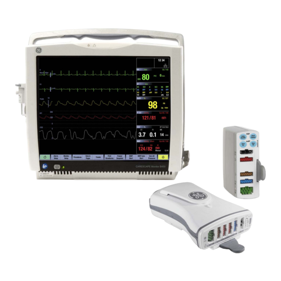
- Page 1 GE Healthcare CARESCAPE Monitor B450 Technical Manual Software Version 2 Hardware Version B450- 01 All specifications subject to change without notice. English 2062973-003 paper September 19, 2016 © 2013, 2016 General Electric Company. All rights reserved.
- Page 2 The information in this manual applies to the software and hardware versions listed on the first page of this manual. Due to continuing product innovation, specifications in this manual are subject to change without notice.
-
Page 3: Table Of Contents
Table of contents Table of contents About this manual Intended use of the manual ............1 Intended audience of the manual. - Page 4 CARESCAPE Monitor B450 User interface symbols ............. . . 34 Using Webmin service interface Local access to Webmin using the integrated browser on the patient monitor .
- Page 5 Table of contents 7.2.2 Selecting and configuring CARESCAPE Network ....... . . 68 7.2.3 Selecting and configuring S/5 Network .
- Page 6 CARESCAPE Monitor B450 8.2.3 Power cord and plug ............102 8.2.4 Ground (earth) integrity .
- Page 7 Table of contents 10.2 Electrical safety checks ............. 130 10.3 Functional check.
- Page 8 CARESCAPE Monitor B450 11.8.8 CARESCAPE Network communication issues ........166 11.8.9 S/5 Network communication issues .
-
Page 9: About This Manual
− 2069156–001 Bedrail Hook Unit, B450 Chapters 1 to 7 provide an overview of the CARESCAPE Monitor B450 patient monitoring system and contains information needed for system installation. Chapters 8 to 13 provide information for the planned and corrective maintenance of the CARESCAPE Monitor B450 main unit. -
Page 10: Product Naming Conventions
CARESCAPE Monitor B450 1.3.1 Product naming conventions In this manual, the CARESCAPE Monitor B450 is referred to as the patient monitor. The following naming conventions are used to refer to different modules and module categories: − PDM: Patient Data Module −... -
Page 11: Trademarks
1.7 Trademarks Listed below are GE Medical Systems Information Technologies, Inc. and GE Healthcare Finland Oy trademarks. All other product and company names contained herein are the property of their respective owners. - Page 12 CARESCAPE Monitor B450 For your notes: 2062973-003...
-
Page 13: Safety Information
Safety information Safety information 2.1 General safety statements See the user’s manual for a list of general safety statements. This device is intended for use under the direct supervision of a licensed health care practitioner. Contact GE for information before connecting any devices to the equipment that are not recommended in this manual. -
Page 14: Safety Symbols
CARESCAPE Monitor B450 2.3 Safety symbols NOTE: The following safety-related symbols appear on one or more of the devices. General warning. This symbol is identified by a yellow background, black triangular band, and a black symbol. General caution sign. IEC 60601-1, 2005 edition This symbol is identified by a white background, black triangular band, and a black symbol. - Page 15 Safety information Type CF (IEC 60601-1) protection against electric shock. Isolated (floating) applied part suitable for intentional external and internal application to the patient, including direct cardiac application. Type CF (IEC 60601-1) defibrillator-proof protection against electric shock. Isolated (floating) applied part suitable for intentional external and internal application to the patient including direct cardiac application.
- Page 16 CARESCAPE Monitor B450 For your notes: 2062973-003...
-
Page 17: System Overview
System overview System overview 3.1 System introduction The CARESCAPE Monitor B450 is a multi-parameter patient monitor for multiple care areas and intra-hospital transport within a professional healthcare facility. 3.2 System components 3.2.1 Monitor The patient monitor can be mains voltage or battery powered. It has an integrated AC/DC power supply unit and it supports up-to two detachable lithium-ion batteries. -
Page 18: Software
CARESCAPE Monitor B450 The touch user interface is the main method for user input. The patient monitor supports also various USB input devices, including a mouse, an alphanumeric keyboard, a barcode reader and a remote controller. The monitor frame has an integrated handle and GCX mounting. The alarm system includes a speaker for audible alarms and a separate alarm light for visual alarms. - Page 19 System overview Keyboard A washable, antibacterial keyboard is specified for use with the monitor. It may be connected to the monitor or display via one of the USB connectors. The keyboard allows you to enter data without using the touchscreen display. Mouse A standard mouse may be connected to the monitor or display via one of the USB connectors.
-
Page 20: Acquisition Modules
CARESCAPE Monitor B450 3.2.4 Acquisition modules The patient monitor includes standard docking for the following multiparameter hemodynamic modules: PSM and PDM. The integrated E-module slot can occupy one single-width E-module at a time. Refer to the patient monitor’s supplemental information manual for a list of compatible acquisition devices and to the patient monitor’s user’s manual for a list of parameters each... -
Page 21: Carescape Network Ix
System overview The MC Network establishes communication and allows patient data to be sent to an optional CIC Pro Clinical Information Center (central station). The S/5 Network establishes communication and allows patient data to be sent to an iCentral (central station). 3.2.6 CARESCAPE Network IX The patient monitor may be connected to the CARESCAPE Network IX. -
Page 22: Unity Network Id Connectivity Device
CARESCAPE Monitor B450 can be created with customer defined resolutions using the hospital-wide login and identification process. The iPanel application is used through a Citrix thin client on the monitor so no additional equipment is required at the bedside. 3.2.7 Unity Network ID connectivity device... -
Page 23: Printers And Recorders
System overview Refer to the patient monitor’s supplemental information manual for a list of compatible displays. 3.2.9 Printers and recorders The patient monitor can print to a recorder and to a laser printer. Refer to the patient monitor’s supplemental information manual for a list of compatible recorders and laser printers. -
Page 24: Service Interface
CARESCAPE Monitor B450 3.2.10 Service Interface Webmin is a browser-based interface that provides service and diagnostic functions for the patient monitor. Using a web browser, the user can connect to Webmin to configure, diagnose and retrieve system information. The user can access Webmin either locally on the patient monitor or remotely over the IX Network. -
Page 25: Controls And Connectors
System overview 3.3 Controls and connectors 3.3.1 Front view Alarm light Power indicator Alarm light Power on/standby button Power indicators Ventilation holes Ambient light detector lens Audio alarm paused/off area (blue) Alarm light area (blue, yellow, or red) Mains voltage indicator - the green LED is lit when the patient monitor is connected to AC mains. -
Page 26: Side Views
CARESCAPE Monitor B450 3.3.2 Side views Battery cover release latch Battery cover Receptacle for power cord and fuse holder Defibrillation synchronization connector Service cover Recorder* Module slot *) optional NOTE: The Defibrillation synchronization connector can be used only with E-PSM(P) modules. -
Page 27: Rear Views
System overview 3.3.3 Rear views Power LEDs for troubleshooting Ventilation holes Slide mount with connector for PDM Cable clamp for power cord Equipotential connector Connectors for input/ output devices and networking Device label Slide mount with connector for PSM 2062973-003... -
Page 28: Service Information
CARESCAPE Monitor B450 Rear panel connectors Network connector for the MC Network & S/5 Network Network connector for the IX Network Network connector for the Unity Network Interface Device (ID) connectivity device Remote-on connector USB ports (2 pcs USB 2.0 Type A connectors) -
Page 29: Equipment Identification
Every GE device has a unique serial number for identification. The serial number is written in a device label. A sample of the information on a device label is shown below. The product code for CARESCAPE Monitor B450 is SNE. 2062973-003... -
Page 30: Product Security
CARESCAPE Monitor B450 3.5 Product security The patient monitoring software incorporates an assortment of security features designed to allow a flexible approach to safe and secure implementation, focusing on the principles of confidentiality, integrity, and availability. These features assist you in using the system in a manner that protects patient privacy and security in your setting, and also addresses expectations for the environment where the system will be used. -
Page 31: Security Operations
System overview The patient monitor performs integrity checking on the root file system to detect any changes to the file system contents. Any modification to the root file system contents will generate an error to the patient monitoring software application. The patient monitoring software will then display a technical alarm to the user. -
Page 32: Product Change Management
CARESCAPE Monitor B450 Outbound Source device Destination Device Protocol Destination port Use icmp ping Patient monitor us1-ws.service.gehealthcare. InSite with ExC (Web Services) us1-rd.service.gehealthcare. InSite with ExC (Remote Tunnel) Citrix Server 1494 Citrix Printer Printing MUSE MUSE Packets that are part of the communication initiated by the patient monitor are allowed into the IX Network (reflexive). -
Page 33: Communication
System overview 3.5.4 Communication For detailed product security information, go to one of the following Web addresses: http://www.gehealthcare.com/usen/security http://www.gehealthcare.com/usen/security/mds2.html 3.6 Equipment symbols The following symbols appear on one or more of the devices. Bell cancel. Audio off. Audio pause. Temporary audio off. General alarm. - Page 34 CARESCAPE Monitor B450 The following symbols appear on one or more of the devices. Battery (monitor): Test button on the battery to check the battery charge level. Battery (monitor). Located on the battery slot cover. Battery (PDM). Communication. (PDM) Power indicator. (PDM) On/standby button.
- Page 35 System overview The following symbols appear on one or more of the devices. Power switch. Display brightness controls. Display speaker volume controls. DVI connector. Video output connector for digital or analog source. Color display connector port. Color video input. Video input connector for digital or analog source. Color video output, digital.
- Page 36 CARESCAPE Monitor B450 The following symbols appear on one or more of the devices. Serial interface. Tram-Net and ePort connector for PDM module, E-module frame Tram-Rac housing, and TRAM modules Gas inlet. Gas outlet. Press to open. Zero all. (PDM) Degree of ingress protection.
- Page 37 System overview The following symbols appear on one or more of the devices. Equipotentiality. Connect device to a potential equalization conductor. Protective earth ground. Connectors grounded to the AC power source. Defibrillator synchronization connectors. (WLAN) Class 2 Identifier Stacking limit by number. Date of manufacture.
- Page 38 CARESCAPE Monitor B450 The following symbols appear on one or more of the devices. Date of manufacture. This symbol indicates the date of manufacture of this device. The first four digits identify the year, the following two digits identify the month, and, if indicated, the last two digits identify the day.
- Page 39 System overview The following symbols appear on one or more of the devices. Keep dry. Protect from rain. Fragile. Handle with care. This way up. This symbol indicates that the waste of electrical and electronic equipment must not be disposed as unsorted municipal waste and must be collected separately.
- Page 40 CARESCAPE Monitor B450 The following symbols appear on one or more of the devices. CAUTION U.S. federal law restricts this device to sale by or on the order of a physician. Russia only. GOST-R mark. Eurasian Economic Union countries only. Eurasian Conformity mark.
- Page 41 System overview The following symbols appear on one or more of the devices. This symbol indicates that this electronic information product does not contain any toxic or hazardous substance or elements above the maximum concentration value established by the Chinese standard SJ/T11363-2006, and can be recycled after being discarded, and should not be casually discarded.
-
Page 42: User Interface Symbols
CARESCAPE Monitor B450 3.7 User interface symbols The following symbols appear in the software user interface Alarm off indicator. Displays in the upper right corner of the parameter window and in the Alarms Setup menu when physiological alarms for this parameter are turned off. - Page 43 System overview The following symbols appear in the software user interface With software version 2 host build 2.0.7 or earlier: General warning sign. Displays when the priority setting for HR/PR high/low, or SpO2 low has been set to low. Displays in the: •...
- Page 44 CARESCAPE Monitor B450 The following symbols appear in the software user interface Monitor battery is full. Monitor battery (green). The higher the charge, the bigger the green bar within the symbol. Numbers indicate the remaining run time. Monitor battery (yellow). This symbol and a message indicating low battery charge appear when there is less than 20 minutes of run time left.
- Page 45 System overview The following symbols appear in the software user interface Respiration indicator. Indicates a breath is detected by the impedance respiration algorithm. BIS and Entropy sensor impedance check indicator (gray). Displays for each sensor as the impedance check is in progress. BIS and Entropy sensor impedance check error indicator (red).
- Page 46 CARESCAPE Monitor B450 For your notes: 2062973-003...
-
Page 47: Using Webmin Service Interface
Using Webmin service interface Using Webmin service interface Webmin is a browser-based service interface that is used to configure the platform settings of the patient monitor and to diagnose and retrieve system information for maintenance and troubleshooting. Local access to Webmin You can access Webmin locally through the integrated browser on the patient monitor or from a configured service PC that is connected to the IX port of the patient monitor with an Ethernet crossover cable. -
Page 48: Local Access To Webmin With A Service Pc
CARESCAPE Monitor B450 Continue to 4.4. Login to Webmin. Closing Webmin Select to close Webmin and return to the main display. 4.2 Local access to Webmin with a service PC You can access Webmin locally by connecting an Ethernet crossover cable between the service PC and the IX connector of the patient monitor. -
Page 49: Remote Access To Webmin Using A Service Pc Over The Ix Network
Using Webmin service interface NOTE: For more information on how to configure the IP address, refer to the PC’s documentation. Launch a web browser on the service PC. In the Address field, type https://[IX IP address]:10000 and press Enter. NOTE: [IX IP address] is the IX Network IP address of the patient monitor. The Login to Webmin dialog box displays. - Page 50 CARESCAPE Monitor B450 Record the IX IP address of the patient monitor: IX IP address: ______________________ IX Netmask: ______________________ Configure the service PC’s IP address and subnet mask to the same network segment with the patient monitor’s IX Network. NOTE: For more information on how to configure the IP address, refer to the PC’s documentation.
-
Page 51: Login To Webmin
Using Webmin service interface 4.4 Login to Webmin In the Login to Webmin dialog box, type the username and password and select Login or press Enter. Username: biomed Password: Change<space>Me NOTE: Username and password are case sensitive. NOTE: “Change Me” is the factory default password for the username “biomed”. Refer to section 7.14. -
Page 52: Webmin Configuration Modules
CARESCAPE Monitor B450 Figure 2 Webmin user interface when accessed using the service PC 4.5 Webmin configuration modules The Webmin service interface includes the following configuration modules. Select Help for additional information related to each Webmin module. 2062973-003... - Page 53 Using Webmin service interface Webmin module Use the module Admit Settings to configure Patient ID Prefix and barcode settings. Citrix to configure the Citrix client settings for the iPanel software: server address, initial program, Citrix session timeout, username, password, encryption level Host Asset Settings to enter a host asset number and to view the host serial number.
-
Page 54: Webmin Information Modules
CARESCAPE Monitor B450 Webmin module Use the module Settings to transfer platform and/or clinical settings from one patient monitor to another, to take backup copies of the settings to an external device and to restore the settings from an external device. -
Page 55: Webmin Diagnostics Modules
Using Webmin service interface 4.7 Webmin diagnostics modules Access Webmin service interface to view hardware statistics, ping a network device, view WLAN diagnostics and view or download log files. The Hardware Statistics module displays several internal voltages, temperatures and power consumption. - Page 56 CARESCAPE Monitor B450 For your notes: 2062973-003...
-
Page 57: Pre-Installation Requirements
Confirm that all components are undamaged. If any of the components is damaged, contact the shipper. Confirm that all components are included. If any of the components is missing, contact your GE Healthcare distributor. WARNING EXCESSIVE LEAKAGE CURRENT - If the device has been transported or stored outside operating temperature range allow it to stabilize back to operating temperature range before removing it from the plastic bag. -
Page 58: Network Infrastructure
CARESCAPE Monitor B450 WARNING The use of accessories, transducers and cables other than those specified may result in increased emissions or decreased immunity performance of the equipment or system. WARNING For detailed instructions and information regarding supplies and accessories, always refer to their own instructions for use. -
Page 59: Network
Pre-installation requirements • Refer to the sections 7.2.3. Selecting and configuring S/5 Network 7.2.4. Configuring WLAN to see the configuration information you need to have available to configure the patient monitor to the S/5 Wireless Network. 5.3.5 IX Network • The IX Network infrastructure shall be installed according to the CARESCAPE Network Configuration Guide. -
Page 60: Power And Environmental Requirements
CARESCAPE Monitor B450 5.6 Power and environmental requirements Check the patient monitor’s supplemental information manual for power and environmental requirements. WARNING Operation of the monitor outside the specified performance range may cause inaccurate results. CAUTION Do not use or store equipment outside the specified temperature, humidity, or altitude ranges. - Page 61 Pre-installation requirements CAUTION Use of known RF sources, such as cell/portable phones, or other radio frequency (RF) emitting equipment near the system may cause unexpected or adverse operation of this device/system. Consult qualified personnel regarding device/system configuration. • The patient monitor should be isolated from sources of strong electromagnetic and radio frequency interference.
- Page 62 CARESCAPE Monitor B450 For your notes: 2062973-003...
-
Page 63: Hardware Installation
Hardware installation Hardware installation CAUTION LOSS OF MONITORING - Leave space for circulation of air to prevent the monitor from overheating. The manufacturer is not responsible for damage to equipment caused by improperly vented cabinets, improper or faulty power, or insufficient wall strength to support equipment mounted on such walls. -
Page 64: Installing The Battery Into The Patient Monitor
CARESCAPE Monitor B450 − Three LEDs illuminated: 50% – 74.9% of full-charge capacity. − Two LEDs illuminated: 25% – 49.9% of full-charge capacity. − One LED illuminated: 10% – 24.9% of full-charge capacity. − One LED flashing: < 10% of full-charge capacity remaining. -
Page 65: Mounting The Patient Monitor
Hardware installation Press the battery door closed until it seals the battery compartment. 6.2 Mounting the patient monitor The patient monitor has an integrated GCX mounting plate. This facilitates all mounting options for the patient monitor. Refer to the CARESCAPE Modular Monitors Mounting Solutions to identify the compatible mounting hardware for the patient monitor. -
Page 66: Connections To D15K And D19Kt Displays
CARESCAPE Monitor B450 WARNING The secondary display will not sound the audible alarms. WARNING To prevent liquids from entering the display, do not tilt the display more than +/-15 degrees. WARNING Use only manufacturer specified mounts. NOTE: Refer to the patient monitor’s supplemental information manual for a list of compatible secondary displays. - Page 67 Hardware installation B) Cable length is 5 to 15 meters If complete isolation is not required, this method will provide the most cost effective means of extending your USB installation. This type of installation should not be used for connections to non-medically used rooms according to IEC 60601-1-1.
-
Page 68: Installing Parameter Modules
CARESCAPE Monitor B450 Secure the USB cables connections to the displays according to the instruction included in the display package. NOTE: The USB connection to the D15K and D19KT secondary display reserves one of the USB connectors in the rear panel of the patient monitor. -
Page 69: Connecting To The Mains Power
Hardware installation Connect the Module Bus Adapter for PSM to the PSM connector in the patient monitor. Connect the cable from the Pole Mount for PSM to the Module Bus Adapter for PSM. Installing a PDM module to a mounting solution: Ensure that the selected PDM mount is properly installed according to the installation instructions included with the mounting hardware. - Page 70 CARESCAPE Monitor B450 patient, the operator, or the environment as a result. In those instances where there is any element of doubt concerning the safety of the connected devices, the user must contact the manufacturers concerned (or other informed experts) for proper use. In all cases, safe and proper operation should be verified with the applicable manufacturer's instructions for use, and system standards IEC60601-1-1 must be complied with.
-
Page 71: Connecting To The Mc Network Or The S/5 Network
This could lead to incorrect drug dose calculations, hemodynamic calculations, or oxygenation calculations. Prior to installing the System, please contact the GE Healthcare Aware Gateway HL7 Integration Engineering Team or your GE Healthcare service representative to verify or update your Aware Gateway configuration. -
Page 72: Connecting Usb Devices
CARESCAPE Monitor B450 CAUTION INSTALLATION - To avoid accidental ingress of liquids, always mount the Unity Network Interface Device (ID) in a vertical position with the connectors at the bottom. • Connect a Unity Network ID connectivity device to the network connector labelled “ID” in the rear panel of the patient monitor. -
Page 73: Connecting A Remote-On Cable
Hardware installation NOTE: Refer to the iCollect User's Manual for more information about the iCollect. NOTE: Contact GE Healthcare Service to get more information about interfacing other data acquisition systems to the patient monitor. 6.11 Connecting a remote-on cable Remote-on connection allows you to power-up the patient monitor from the power switch of a GE Healthcare anesthesia machine. - Page 74 CARESCAPE Monitor B450 individual earth leakage currents of the system if there is an interruption of the multiple socket outlet protective earth conductor. WARNING Non-medical equipment does not provide the same level of protection against electrical shock. Do not touch the patient and any part of non-medical equipment at the same time.
-
Page 75: Configuration
Configuration Configuration The configuration of the patient monitor consists of platform configuration and clinical configuration. This chapter describes how to perform the platform configuration tasks needed to take the patient monitor into use for the first time and the configuration tasks needed for administration and maintenance thereafter. -
Page 76: Selecting And Configuring Carescape Network
CARESCAPE Monitor B450 Enter the new hostname in the Change Value to column. NOTE: The hostname is a unique, 4 to 32 character long identifier of a patient monitor in the network. Use alphanumeric characters A-Z, a-z, 0-9. The hostname may include also characters “-”... -
Page 77: Selecting And Configuring S/5 Network
Configuration The network configurations will be saved and become active when the patient monitor is restarted. 7.2.3 Selecting and configuring S/5 Network To select S/5 Network for the real-time network infrastructure: Log in to Webmin. Select Configuration > Network > Wired Interfaces. The current network configuration is shown in the Present Configuration table. - Page 78 CARESCAPE Monitor B450 NOTE: Antenna diversity is a method used to assist in compensating for multipath interference. When set to Enabled, Antenna Diversity monitors the signal from each antenna and automatically switches to the one with the better signal. Configure the appropriate WLAN settings. Note that the configurable attributes and available values are different for MC Network and S/5 Network.
- Page 79 Configuration WLAN Client Configuration Item Description Comments Region Select the WLAN region mode from The region setting is used to set the maximum one of the following options: transmit power and allowed channels for the WLAN radio card. If your country or region is not listed, select World Mode.
- Page 80 CARESCAPE Monitor B450 WLAN Client Configuration Item Description Comments WMM AC Parameters Configure the WMM AC Parameters WLAN Multimedia (WMM) provide basic Quality (CWmin, CWmax, AIFS, TXOP) for of Service (QoS) features to IEEE802.11 networks each access category (voice, video,...
- Page 81 Configuration WLAN Client Configuration Item Description Comments SSID Enter the Service Set Identifier (SSID), The SSID of the wireless client must match the also known as network name. SSID of the wireless infrastructure. A valid SSID includes up to 32 case-sensitive ASCII characters, including space (ASCII decimal 32 to 126).
-
Page 82: Setting Time And Date
CARESCAPE Monitor B450 WLAN Client Configuration Item Description Comments Pass Phrase / Key Enter the Pass Phrase / Key for the The Pass Phrase / Key of the wireless client must used confidentiality method as an match the Pass Phrase / Key of the wireless ASCII or HEX string as selected infrastructure. -
Page 83: Setting Unit And Bed Name
Configuration In the Time Configuration window, in Configure Date and Time, update the following fields as needed: • Date • Month • Year • Hour:Minute • AM/PM • 12/24 Hrs In the Time Configuration window, in Configure Time Zone, select the appropriate UTC Offset, if applicable. -
Page 84: Deleting A Printer
CARESCAPE Monitor B450 In the Sub-Modules for Printers menu, select Install Printer. Below Printer Configuration Information in the Install Printer window, provide the following information: Select either the Hostname or IP Address radio button, as applicable. In the Hostname or IP Address field, enter the printer Hostname or IP Address. -
Page 85: Configuring Muse/12Sl
Configuration Field name Description and valid choices Server Version Select the supported server version: 4.0, 4.5, 5.0, 6.0, 6.5. Server 1 to Server 4 Addresses Blank, server IP address or server hostname, up to 255 character long. Initial Program Initial Citrix- published application that will be launched, for example #MUSE. -
Page 86: Admit Settings
CARESCAPE Monitor B450 Location ID Identifies the location ID number (within the range 0 to 599) associated with the patient monitor for searching the MUSE system. Site Number Identifies the site number (within the range 1 to 254) associated with the patient monitor for searching the MUSE system. -
Page 87: Barcode Settings
Configuration 7.8.2 Barcode settings Barcode settings must be configured if a barcode reader is used to input patient data to the Admit/Discharge menu. NOTE: Acquire detailed specification of the character-delimited or the length-delimited, multi-field barcode that the hospital uses. This will configure the barcode parser correctly. NOTE: Acquire sample barcodes, if possible, to verify the operation of the parser configuration. - Page 88 CARESCAPE Monitor B450 In the Position column, type the beginning position of the field in the data string (from 1 to 300). In the Length column, type the number of characters (from 1 to 99) that the field contains. For Gender Format, select Fixed or Configured.
-
Page 89: Configure Character Delimited Parser Information
Configuration 7.8.4 Configure character delimited parser information Points to note − If you configure Age, you must either select the Age Unit item or one of the age units (e.g., Years, Months, Weeks, Days) below Fixed Option. − If you configure Height, you must either select the Height Unit item or one of the height units (e.g., Feet, Inches, Meters, Centimeters, Millimeters) below Fixed Option. - Page 90 CARESCAPE Monitor B450 In the Position column of the Admit/Discharge Configuration window, enter the sequence number of each item included in the barcode. Use incremental numbers from 1 (the left-most field) up to 16 (the right-most field). If an item is not included in the barcode, leave the Position field blank for the item.
-
Page 91: Barcode Data Specifications
Configuration Item Sequence number of the item in the barcode Height Height Unit Weight The following sample shows the corresponding entries in the Admit/Discharge Configuration window. 7.8.5 Barcode data specifications Points to note − The maximum length of the entire barcode is 300. 2062973-003... - Page 92 CARESCAPE Monitor B450 − If the field value is longer than the maximum length indicated, the right-most characters will be truncated when the value is displayed in the Admit/Discharge menu. If a field contains a forbidden character, that character will be replaced with a space when it is displayed in the Admit/Discharge menu.
-
Page 93: Setting Power Frequency
Configuration 7.9 Setting power frequency WARNING Incorrect power line frequency setting could adversely affect ECG and EEG processing. Log in to Webmin. Select Configuration > Power Frequency. In the Power Frequency window, select the applicable power line frequency. Select Save. The power frequency configuration takes effect immediately. -
Page 94: Module Asset Settings
CARESCAPE Monitor B450 Refer to the Module Frames and Modules Technical Manual for detailed information on how to change these settings. Webmin Module Description sub-module Assets Settings This setting allows you to view the customer assigned asset number of the PDM. -
Page 95: Restarting The Patient Monitor
Configuration WARNING Control of this user’s password is critical to ensure that Webmin on this device is accessed only by trained and authorized personnel. Failure to limit access of Webmin to trained and authorized personnel only may compromise patient safety and/or system performance. NOTE: Username and password are case sensitive. -
Page 96: Enabling Remote Service Agent/ Connection
CARESCAPE Monitor B450 In the Remote Service Configuration window, enter the applicable data: HTTP Proxy Server Configuration Item Description Comments Address If this site uses an HTTP proxy server, a These values are specific site proxy server IP Address and... -
Page 97: Testing The Connectivity
Configuration 7.16.3 Testing the connectivity NOTE: Connectivity test works only if the connection is enabled, that is the current state is enabled/running. Log in to Webmin. Select Configuration > Remote Service. In the Sub-Modules for Remote Service menu, select Control. Below Test Connectivity in the Remote Service Control window, select Test to test the connectivity to the remote service server. -
Page 98: Loading Settings
CARESCAPE Monitor B450 Select Configuration > Settings. In the Sub-Modules for Settings menu, select Save. In the Save Settings window, select the radio button next to the type of settings you want to save. Select Save. According to your Webmin access:... - Page 99 Configuration activation process with a delay during an active patient case, but the new settings will activate only after the next case reset / patient discharged. Log in to Webmin. Select Configuration > Settings. In the Sub-Modules for Settings menu, select Activate. In the Activate Settings window, select the settings that you want to activate: •...
-
Page 100: Canceling Pending Settings Activation
CARESCAPE Monitor B450 NOTE: Activation of the factory defaults and US factory defaults will leave the following settings in the target patient monitor unaffected: - Host Asset Settings - Licenses In the Setting Activation, select whether you want the new settings to take effect... -
Page 101: License Management
Alternatively, you can enable and activate individual software packages and host software feature licenses by entering the required activation code manually. NOTE: Contact GE Healthcare to acquire activation codes for licenses. 7.18.1 Enabling and activating host software package NOTE: As a factory default, the ICU software package is always activated. -
Page 102: Uploading License File
To begin software installation, you first transfer the new software into the inactive memory partition of the patient monitor. Transfer software using the GE Healthcare Software Transfer Utility that runs on a service PC. With this application, you can transfer new software from a software CD to the patient monitors over the CARESCAPE Network IX (IX Network) or a crossover cable. -
Page 103: Activating The Installed Software
Supplemental Information Manual for a list of compatible network and bedside devices. • Contact GE Healthcare to get the latest version of the user and service documentation • Contact GE Healthcare for any inquiries regarding the software CD and/or activation code for the new host software version. - Page 104 CARESCAPE Monitor B450 Activating host software immediately Before you start: • Make sure the patient monitor is in a case reset / patient discharged state. In the Host Software window, verify that the software you are activating is listed as Inactive in Current Software State.
- Page 105 Configuration Software activation in progress. Do not disconnect any measurement modules or other peripheral devices, or shut down the monitor until the software activation is complete. Activation may take up to 10 minutes. The device will automatically restart once the software activation is complete. NOTE: When the software is activated first time after a uDOM replacement, the screen saver does not appear.
- Page 106 CARESCAPE Monitor B450 In Erase Inactive Software After Activation, select: to keep the currently active software version as inactive software after the new software version is activated successfully. This option lets you restore the patient monitor to the previous software version later.
-
Page 107: Canceling Pending Host Software Activation
Configuration activation is completed and the parameter module has restarted. This may take up to 15 minutes. Do not shut down the patient monitor or disconnect the parameter modules. The parameter module restarts automatically after the software activation is complete. After the parameter module restarts, verify that the software activation is successful and the parameter module runs the activated software. - Page 108 CARESCAPE Monitor B450 For your notes: 2062973-003...
-
Page 109: Installation Checkout
Installation checkout Installation checkout The purpose of the installation checkout procedure is to ensure that the system is properly installed and configured for use. Service personnel shall perform the following checkout procedure for the monitoring system after the hardware installation and platform configuration is completed: •... -
Page 110: Power Outlet
CARESCAPE Monitor B450 Tool Part Number / Requirement Safety Analyzer / Leakage Current Tester Equivalent to the circuits shown. Safety Test Body Kit P/N M1155870 or equivalent Instead of the test bodies included in the safety test body kit, other applicable test bodies with all pins connected together may be used. - Page 111 Installation checkout Acceptance criteria: • For equipment without a power supply cord, the impedance between the protective earth terminal and any accessible metal part which is protectively earthed shall not exceed 0.1 ohms. • For equipment with a power supply cord, the impedance between the protective earth pin in the mains plug and any accessible metal part which is protectively earthed shall not exceed 0.2 ohms.
-
Page 112: Earth Leakage Current Test
CARESCAPE Monitor B450 8.2.5 Earth leakage current test This test measures the current leakage flowing from the mains part through or across the insulation into the protective earth conductor of the device under test. Perform this test both in Normal Condition (NC) and in a Single Fault Condition (SFC), where one of the supply conductors is open at a time. -
Page 113: Enclosure Leakage Current (Touch Current) Test
Installation checkout Read and record the current leakage indicated on the safety tester. 10. Power off the device under test. Acceptance criteria in Normal Condition (NC): • All readings shall be less than or equal to 300 μA for installations that require compliance to UL 60601-1 requirements. - Page 114 CARESCAPE Monitor B450 Read and record the current leakage indicated on the safety tester. Configure the safety analyzer as follows (SFC): − Polarity: NORMAL − Neutral: OPEN − Earth (GND): CLOSED Read and record the current leakage indicated on the safety tester.
-
Page 115: Patient Leakage Current Tests - Overview
Installation checkout All readings shall be less than or equal to 300 μA for installations that require compliance • to UL 60601-1 requirements. All readings shall be less than or equal to 500 μA for installations that require compliance • to EN 60601-1 / IEC 60601-1 requirements. -
Page 116: Patient (Source) Leakage Current Tests
CARESCAPE Monitor B450 8.2.8 Patient (source) leakage current tests This procedure measures the leakage current from an applied part connector of the device to ground. Perform the test in Normal Condition (NC) and in two different Single Fault Conditions (SFC): 1) earth open and 2) one of the supply conductors open at a time. -
Page 117: Patient (Sink) Leakage Current Tests
Installation checkout − Polarity: REVERSED − Neutral: CLOSED − Earth (GND): OPEN Read and record the current leakage indicated on the safety tester. 10. Configure the safety analyzer as follows (SFC): − Polarity: REVERSED − Neutral: OPEN − Earth (GND): CLOSED 11. -
Page 118: Test Completion
CARESCAPE Monitor B450 NOTE: *The measuring device (MD) represents the network and voltage measuring instrument and its frequency characters according to IEC 60601-1. NOTE: **According to IEC-60601, the impedance to protect the circuitry and the person performing the test, but low enough to accept currents higher than the allowable values of the leakage current to be measured. -
Page 119: Display
Installation checkout monitor batteries and disconnecting the power cord from the wall outlet for a moment before turning the monitor on. Verify that the patient monitor starts up normally: − The yellow, red and blue alarm lights are lit momentarily. −... -
Page 120: Keypad And Remote
CARESCAPE Monitor B450 − S/5 printers are correctly configured. − IX printers and printer locations are correctly configured. − Remote service is correctly configured. − National requirements are correctly configured. − Network is correctly configured. − Power Line Frequency is correctly configured. -
Page 121: Mc Network And S/5 Network
Installation checkout Parser Type Test Procedure Length Delimited or Character 4. Select Scan from Barcode. Delimited Parser 5. Scan a known test barcode obtained from the hospital. NOTE: The barcode data content must be known and in compliance with the completed parser configuration. 6. -
Page 122: Printers
CARESCAPE Monitor B450 NOTE: Make sure that at least one other patient monitor is on the network. The other patient monitor must be in an admitted state and have an active ECG measurement with a simulator signal. Checkout procedure for wireless patient monitors Check each wireless patient monitor according to the following procedure. -
Page 123: Ipanel Connection
Installation checkout 8.3.12 iPanel connection Perform the following test only if the Citrix / iPanel is configured and in use. Select Data & Pages > iPanel and verify that the initial program (configured in Webmin) is launched correctly. Select to exit the Citrix thin client. 8.3.13 Insite with EXC Perform the following test only if remote service is configured and enabled, and you did not test the connectivity already while you enabled it. - Page 124 CARESCAPE Monitor B450 For your notes: 2062973-003...
-
Page 125: Theory Of Operation
Theory of operation Theory of operation Figure 3 CARESCAPE Monitor B450 System block diagram The system block diagram shows the functional units of the CARESCAPE Monitor B450. 2062973-003... -
Page 126: Power Supply/ Power Management Subsystem
CARESCAPE Monitor B450 The following sections describe the operation and interaction of the different subsystems. 9.1 Power Supply/ Power management subsystem 9.1.1 AC/DC Power Supply Power Entry Module The power entry module consists of an appliance inlet and mains filter. The fuses in the appliance inlet provide the input protection. -
Page 127: Dc/Dc Board
Theory of operation 9.2 DC/DC Board Figure 4 CARESCAPE Monitor B450 DC/DC Board Block Diagram 2062973-003... -
Page 128: Puic Controller And Software
CARESCAPE Monitor B450 9.2.1 PUIC controller and software The Power Management and User Interface Controller (PUIC) software controls the hardware related functions of the DC/DC and user interface controller subsystems. The PUIC software is included in the host software package and upgradeable via software CD. -
Page 129: User Interface Controller (Uic) Subsystem
Theory of operation 9.2.3 User Interface Controller (UIC) subsystem The User Interface Controller (UIC) subsystem manages the following user interface related functions. Alarm light control • PUIC controller controls the alarm light LEDs according to the information received from the CPU assembly. •... -
Page 130: Cpu Assembly
CARESCAPE Monitor B450 9.3 CPU assembly Figure 5 CARESCAPE Monitor B450 CPU board block diagram 2062973-003... -
Page 131: Cpu Carrier Board
Theory of operation 9.3.1 CPU carrier board DC/DC subsystem The DC/DC subsystem takes care of the following voltage conversions. The VSYS voltage is converted to +5V and +3.3. V supply voltages by a step-down converter: • +5V is supplied for the external USB connectors, alarm light board, audio amplifier and for the optional WLAN module and recorder. - Page 132 CARESCAPE Monitor B450 Ethernet subsystem The CPU carrier board has a 5-port Ethernet switch. The interfaces provided by the Ethernet switch share the same MAC address. The Ethernet host is in the CPU module. The Ethernet switch port usage is as follows: •...
-
Page 133: Udom
Theory of operation The external connectors have ESD protection. RJ-45 connectors are electrically isolated by Ethernet transformers. 9.3.2 uDOM A detachable, non-volatile flash memory, USB Disk On Module (uDOM), is used as the permanent memory for application and service software and to store clinical and platform settings. -
Page 134: Touchscreen Sensor
CARESCAPE Monitor B450 9.4.2 Touchscreen sensor The patient monitor has a resistive touchscreen sensor in the front of the LCD panel. The touchscreen sensor detects the presence and location of a touch within the display area and communicates the information through the touchscreen cable to the touchscreen controller at/ on the DC/DC board. -
Page 135: Module Rail Unit
Theory of operation 9.4.9 Module Rail Unit The Module Rail Unit connects to the CPU carrier board. It provides interfaces for PSM and PDM modules: • The 10-pin PDM connector provides the VSYS PDM supply voltage and the Ethernet communication lines to the PDM module. •... - Page 136 CARESCAPE Monitor B450 For your notes: 2062973-003...
-
Page 137: Maintenance And Checkout
Maintenance and checkout 10 Maintenance and checkout This chapter specifies the checkout procedure and the maintenance activities to be performed to the patient monitor after corrective maintenance and during annual planned maintenance. This chapter also covers the battery maintenance information for the patient monitor’s lithium- ion battery. -
Page 138: Visual Inspection
CARESCAPE Monitor B450 Required checkout procedure Visual Electrical Functional check Performed service activity inspections safety test (section 10.3) (section 10.1) (section 10.2) After detaching, replacing or 10.3.1 Start-up upgrading: 10.3.14 Recorder Recorder unit (FRU / Upgrade) After detaching or replacing: 10.3.1 Start-up... -
Page 139: Functional Check
Maintenance and checkout Record the values of the tests on the Appendix B. Maintenance check form. 10.3 Functional check 10.3.1 Start-up Follow the procedure in section 8.3.1. Start-up. 10.3.2 Display Follow the procedure in section 8.3.2. Display. 10.3.3 PSM / PDM identification Configure the ECG1 waveform field and the NIBP parameter window to the patient monitor screen with adequate priority. -
Page 140: Wireless Lan
CARESCAPE Monitor B450 10.3.10 Wireless LAN Follow the procedure in section 8.3.10. Wireless LAN. 10.3.11 IX printers Follow the procedure in section 8.3.11. IX printers. 10.3.12iPanel connection Follow the procedure in section 8.3.12. iPanel connection. 10.3.13 Insite with Exc Follow the procedure in section 8.3.13. - Page 141 Maintenance and checkout − Analog output cable (2000633-001) NOTE: You can alternatively use the GE defib sync tester, 2040582-001, together with the Analog output cable, 2000633-001 and a multiparameter simulator to perform this test. Follow the instructions included with the tester. See analog output cable wire colors and related signals from the table below.
- Page 142 CARESCAPE Monitor B450 − Scale (mmHg): 0-200 mmHg. − Parameter Format: Sys/Dia (Mean). Configuring the simulator Refer to the simulator documentation for details on how to use and configure the simulator. Configure ECG: − ECG rhythm: a normal sinus rhythm.
-
Page 143: 16Test Completion
Maintenance and checkout Change the oscilloscope Volts scale: IP analog output signal: Yellow Analog GND: Blue or White Probe Type: x10 Time/Division: 200 mS Volts/Division: 0.2V Verify that the Arterial BP output waveform shown on the oscilloscope screen corresponds to the P1 waveform on the monitor screen. Test the frequency of the Marker out signal Connect the oscilloscope probe to the marker out signal (black wire) and common ground (red wire). -
Page 144: Monitor Battery Maintenance
CARESCAPE Monitor B450 10.4 Monitor battery maintenance The lithium-ion (Li-Ion) battery is a rechargeable battery containing lithium-ion cells. Each battery contains an integrated electronic fuel gauge and a safety protection circuit. The following are facts about lithium-ion battery technology: −... -
Page 145: Conditioning A Battery
Maintenance and checkout 10.4.5 Conditioning a battery Condition the battery when a Condition Battery A or Condition Battery B message is shown on the monitor screen. The condition cycle recalibrates the electronic fuel gauge. Condition the battery by fully discharging and recharging the battery twice according to the following procedure: NOTE: The patient monitor must be in a discharged state during battery conditioning. - Page 146 CARESCAPE Monitor B450 USA: You may follow the battery manufacturers instructions on the battery • recycle it. Alternatively, you may return GE product batteries to GE for recycling. For information about returning batteries to GE, contact your authorized GE Service representative or contact GE Equipment Services at 1-800-437-1171.
-
Page 147: Troubleshooting
Troubleshooting 11 Troubleshooting The problems and solutions in this section represent only a few of the faults that you may encounter and are not intended to cover every possible problem that may occur. This chapter focuses on troubleshooting technical problems. See the patient monitor’s user’s manual for troubleshooting monitoring problems and clinical configuration issues. -
Page 148: Configuration Information
CARESCAPE Monitor B450 11.2.1 Configuration information The Configuration Information module shows the current platform configuration of the patient monitor and the connected peripheral devices. To view configuration information: Log in to the Webmin. Select the Information tab. Select Configuration Information. -
Page 149: Device Information
Troubleshooting Configuration information • Default Clinical Settings Current default clinical settings. • Admit Settings Patient ID Prefix. Citrix • Server address, initial program, session timeout in minutes, username and encryption level. • Unit and Bed Name Unit name and Bed name for CARESCAPE Network. •... -
Page 150: Webmin - Diagnostics Tab
CARESCAPE Monitor B450 Select the Information tab. Select Device Information. Scroll down the page to view the device information: Device information • Host Information Active software part number and version, Inactive software part number and version, Host serial number, Host asset number, MC Network IP address, IX Network IP... -
Page 151: Hardware Statistics
Troubleshooting 11.3.1 Hardware statistics The Hardware Statistics module displays several internal voltages, temperatures and power consumption. A value is displayed in red, if the current reading exceeds a pre-determined lower or upper limit, A value is displayed either as “0” or as “--”, if it cannot be measured. To access hardware statistics: Log in to Webmin. - Page 152 CARESCAPE Monitor B450 DC/DC Board Measurement Description AC/DC voltage (mV) The AC/DC voltage is generated by the AC/DC power supply unit and supplied as an input voltage to the DC/DC board. The voltage is measured from the DC/DC board. The AC/DC voltage is “0”, if the patient monitor is not connected to the AC mains.
-
Page 153: Ping A Tcp/Ip Network Device
Troubleshooting DC/DC Board Measurement Description System power (mW) System power is the total power consumption of the patient Power consumption is measured from the DC/DC monitor. board. DC/DC temperature (°C) The internal temperature of the patient monitor measured by the temperature sensor in the DC/DC board. CPU Carrier Board Measurement Description... -
Page 154: Wlan Diagnostics
CARESCAPE Monitor B450 Log in to Webmin. Select Diagnostics > Ping. In the Address to Ping field in the Ping Command window, type the IP address of a known device on the network and select ping. If you receive a reply, then you are able to connect to the device. - Page 155 Troubleshooting Contents • WLAN Status WLAN radio • WLAN client IP Address • Antenna diversity mode • Region mode • Center frequency (i.e., the current actual center frequency, which is associated with the operating channel number used, e.g in the 2.4 GHz band on channel 6, the displayed frequency should be 2.437 GHz.) •...
- Page 156 CARESCAPE Monitor B450 Contents • WLAN status The current Association/Authentication status of the WLAN Radio: Association/ Description of the state Authentication state Disconnected The WLAN client radio is not authenticated or associated to any network infrastructure. Authenticating The network infrastructure is authenticating the WLAN client radio.
-
Page 157: Log Files
Troubleshooting 11.3.4 Log files The patient monitor collects information about different system events and errors to log files. These log files help troubleshooting problems in the patient monitor and the connected peripheral devices. The following table describes the available log files and the type of information that they collect. - Page 158 CARESCAPE Monitor B450 Log file name Contents PDM log All PDM errors and messages. • System log OS events and errors, including operating system related information, such as clinical application startup and recovery information, power on self-test results, etc. •...
-
Page 159: Power Management Leds
Troubleshooting Select the log file you want to view. Select the information you want to view. • For the Webmin Action Log, select the user, module, and timeframe and select Search. • For the other types of logs, select the link associated with the information you want to view. -
Page 160: Network Status Leds
CARESCAPE Monitor B450 Description ACDC (green, H7) The green ACDC LED should be lit when the patient monitor is connected to the AC mains, even if the patient monitor is in standby mode. A lit LED indicates that the DC/DC board receives the 15.2-16.2 VDC from the AC/DC power supply unit. -
Page 161: Battery Diagnostics
Troubleshooting 11.6 Battery diagnostics You can check the monitor battery status from the Battery Status menu. Select Monitor Setup > Battery Status The Monitor Battery Status menu will open. The information is shown separately for each battery, A and B. Field Status Description... -
Page 162: Error Messages And Codes
CARESCAPE Monitor B450 For more detailed information, select Advanced tab. Field Description Remaining capacity (mAh) Remaining capacity of the battery in mAh. Full capacity (mAh) Full capacity of the battery in mAh. Full capacity compared to new (%) Full capacity of the battery compared to the nominal full capacity of a new battery. - Page 163 Troubleshooting Message Possible causes Possible solutions Identical A patient monitor with the Disconnect the patient monitor that IP address identical IP address is on the has the identical IP address. noticed network. Change the IP address of the patient monitor that has the duplicate IP address.
- Page 164 CARESCAPE Monitor B450 Message Possible causes Possible solutions External alarm 1. The USB cable between the 1. Reconnect the USB cable. light disconnect. patient monitor and the Check USB secondary display is connection. disconnected when the patient is admitted. 2. Secondary display turned to 2.
- Page 165 Troubleshooting Message Possible causes Possible solutions Replace battery A The full capacity of the battery Replace the monitor battery with a new is less than or equal to 50% one. Replace battery B compared to the full capacity of a new battery. Battery A failure Battery failure.
-
Page 166: Problems And Solutions
CARESCAPE Monitor B450 11.8 Problems and solutions Start-up failures 11.8.1 Problem Possible causes Recommended actions Unable to turn on the patient Power cord is loose. Ensure that the power cord is connected properly monitor when it is powered to the wall outlet and to the patient monitor. - Page 167 Troubleshooting Problem Possible causes Recommended actions Unable to turn on the patient The cable between user Check the status of the red ON/Stdby-button LED monitor when it is both interface board and DC/ on DC/DC board when On/Stdby button is pushed. connected to AC mains and DC board is loose or faulty.
-
Page 168: User Interface Issues
CARESCAPE Monitor B450 Problem Possible causes Recommended actions Unable to turn on the patient The display cable is Check that the display cable is intact and properly monitor: damaged or loose. connected to the LCD display and the CPU board. - Page 169 Troubleshooting On/standby button and alarm light issues Problem Possible cause Recommended action On/Standby and the power User interface cable is loose or Check user interface cable and replace it, indicator LEDs are inoperative. faulty. if necessary User interface board is faulty. Replace the user interface board.
-
Page 170: Incorrect System Time
CARESCAPE Monitor B450 Audible alarms do not work. Audible alarms are turned off Enable audible alarms. (See Alarms Setup > Audible & Visual.) Alarm volume is low. Adjust alarm volume (Monitor Setup > Sound Volumes). Speaker failure Replace the speaker unit. -
Page 171: License Issues
Troubleshooting 11.8.4 License issues Problem Possible cause Recommended action Unable to perform a function or A license has not been See License management chapter. a feature is not available. purchased for the feature. The trial license has expired for the feature. The license is not installed properly. -
Page 172: Recorder Issues
CARESCAPE Monitor B450 11.8.6 Recorder issues Problem Possible cause Recommended action Recorder does not work. Graph location is not configured Check the configuration: Monitor Setup > correctly. Printing > Devices > Setup. Recorder unit failure. Replace the recorder unit. CPU board failure... - Page 173 Troubleshooting E-module issues Possible cause Recommended action Incompatible module Refer to the patient monitor’s supplemental information manual document to see the list of compatible modules. DC/DC board failure The +15 V MOD supply voltage for the E-module board is generated in the DC/DC board.
-
Page 174: Carescape Network Communication Issues
CARESCAPE Monitor B450 PDM module issues Possible cause Recommended action DC/DC board failure The VSYS supply voltage for the PDM module is generated in the DC/DC board. Check from the Webmin Hardware Statistics that the supply voltages are within specification:... - Page 175 Troubleshooting 2062973-003...
- Page 176 CARESCAPE Monitor B450 Problem: No waveforms or parameters are displayed at the CIC Pro center 2062973-003...
- Page 177 Troubleshooting 2062973-003...
-
Page 178: S/5 Network Communication Issues
CARESCAPE Monitor B450 11.8.9 S/5 Network communication issues Check the following things before proceeding with any detailed network troubleshooting: • Check status of the wired and wirelessnetwork connection indicators and the WLAN signal strength indicator, for reference see “3.7”. •... - Page 179 Troubleshooting Wireless S/5 network Problem Possible cause Recommended action • Contact the hospital IT No wireless connection - the Patient monitor is out of wireless department to check the patient monitor does not coverage area. wireless coverage area. associate/authenticate with the Access Point, see section •...
- Page 180 CARESCAPE Monitor B450 For your notes: 2062973-003...
-
Page 181: Disassembly And Reassembly
Disassembly and reassembly 12 Disassembly and reassembly 12.1 Disassembly guidelines Field repair of the patient monitor is limited to replacing Field Replaceable Units (FRUs). See chapter 13. Service parts for a detailed list of available FRUs. Attempting a field repair on a printed circuit board or a factory sealed component or assembly could jeopardize the safe and effective operation of the patient monitor. -
Page 182: Required Tools
CARESCAPE Monitor B450 more than three times. Use only new screws attaching into light metal parts. Take advantage of existing thread pattern cut by turning the screw counterclockwise until it drops into the existing thread pattern. • We have added the maximum recommended torque value to be used for each screw and nut in reassembly. - Page 183 Disassembly and reassembly WARNING ELECTRIC SHOCK - Always unplug the grounded cables when not in use. Leaving them connected could result in an electric shock from the ground contact in the other end. On/standby Turn the patient monitor off from the button.
- Page 184 CARESCAPE Monitor B450 Disassembly workflow Use this workflow diagram to find the simplest way to disassemble the required parts of the patient monitor. Numbers in the diagram refer to the sections in this Disassembly chapter. Follow the arrows from the top down to the required part and disassemble the monitor by following the steps in between.
-
Page 185: Disassembly Procedures
Disassembly and reassembly 12.2 Disassembly procedures 12.2.1 Replacing the recorder unit (FRU) 1. Open the recorder door and remove the paper roll if installed. 2. Release the two snaps on each side of the recorder by pressing with a flat blade screwdriver. -
Page 186: Replacing The Mains Fuses (Fru)
CARESCAPE Monitor B450 12.2.2 Replacing the mains fuses (FRU) The mains fuses are located on the side of the monitor, inside the AC inlet. 1. Release the snap in the fuse holder of the AC inlet by pressing it with a flat blade screwdriver. -
Page 187: Replacing The Cpu Battery (Fru)
Disassembly and reassembly 12.2.3 Replacing the CPU battery (FRU) To avoid network device time synchronization issues, remember to readjust the time and date before you connect the monitor to network. For details, see Setting time and date. 1. Remove the screw (T10) holding the service cover. - Page 188 CARESCAPE Monitor B450 3. Pull out the service cover. 4. Detach the CPU battery from the CPU carrier board with a flat blade screwdriver. NOTE: Dispose the battery according to local, state or country laws. • Reassemble in reverse order.
-
Page 189: Replacing The Battery Door Unit (Fru)
Disassembly and reassembly 12.2.4 Replacing the battery door unit (FRU) 1. Open the battery door. 2. Release the snap that holds the battery door assembly to the patient monitor using a flat blade screwdriver. 3. Pull the battery door assembly out of the patient monitor. -
Page 190: Replacing The Module Rail Unit (Fru)
CARESCAPE Monitor B450 12.2.5 Replacing the module rail unit (FRU) 1. Remove the four screws (T10) that mount the module rail unit to the rear unit assembly. NOTE: Notice the torque during the reassembly: if you replaced the CPU assembly, use 1.2 Nm. -
Page 191: Detaching The Front Unit And Mid-Frame Assembly From The Rear Unit Assembly
Disassembly and reassembly 12.2.6 Detaching the front unit and mid-frame assembly from the rear unit assembly This step only for monitors without a recorder unit: 1. Use a flat blade screwdriver to release the snap that fastens the recorder cover plate to the monitor frame. - Page 192 CARESCAPE Monitor B450 5. Carefully detach the alarm light lens. Release the snaps holding the alarm light lens by sliding a flat blade screw driver under the lens and carefully lift the lens up using the screw driver. 6. Remove the three screws (T10) in the bottom of the patient monitor.
- Page 193 Disassembly and reassembly 9. Pull out the front unit and mid-frame assembly from the rear unit assembly a little so that you have access to the AC/DC and display cables. 10. Detach the AC/DC cable from the DC/DC board connector. 2062973-003...
- Page 194 CARESCAPE Monitor B450 11. Detach the display cable from the CPU carrier board. 12. Pull out the front unit and mid-frame assembly all way out from the rear unit assembly. Reassemble in reverse order: When reassembling, ensure that the connector in the E-module board is properly aligned with the connector in the CPU carrier board.
-
Page 195: Detaching The Udom
Disassembly and reassembly 12.2.7 Detaching the uDOM Disassemble first: 12.2.6. Detaching the front unit and mid-frame assembly from the rear unit assembly Keep the rear unit assembly on the table, the device label side facing down. 1. Carefully detach the uDOM from the CPU assembly. -
Page 196: Detaching The Cpu Assembly (Fru)
CARESCAPE Monitor B450 12.2.8 Detaching the CPU assembly (FRU) The CPU assembly consists of CPU carrier board, CPU module and uDOM. Disassemble first: 12.2.6. Detaching the front unit and mid-frame assembly from the rear unit assembly Keep the rear unit assembly upright on the table. - Page 197 Disassembly and reassembly 3. Detach the WLAN card from the CPU carrier board, if installed. a. Remove the two screws (T6) that hold the WLAN radio card to the CPU carrier board. Torque [0.3 Nm]. b. Detach the WLAN radio card carefully from its connector in the CPU carrier board.
- Page 198 CARESCAPE Monitor B450 • FRU, CPU assembly, B450 Reassemble in reverse order. Note the following: Step 6: Remember to first reattach the original uDOM to the CPU assembly. Step 5: When reassembling the CPU assembly, make sure to first place the heat sink under the plastic lip of the rear unit assembly.
- Page 199 Disassembly and reassembly Step 3: Remember to reattach the WLAN radio card back to the CPU assembly. Place the WLAN antenna guide around the CPU board connector before reattaching the connector. Step 1: Check the correct position of the CPU assembly and the AC/DC power supply unit before you fasten the four screws (T10) that hold the CPU assembly and the module rail unit to the rear unit assembly.
-
Page 200: Replacing The Ac/Dc Power Supply Unit (Fru)
CARESCAPE Monitor B450 12.2.9 Replacing the AC/DC power supply unit (FRU) Disassemble first: 12.2.6. Detaching the front unit and mid-frame assembly from the rear unit assembly 12.2.8. Detaching the CPU assembly (FRU) Keep the rear unit assembly on the table, the device label side facing down. -
Page 201: 10Replacing The Wlan Assembly (Fru)
Disassembly and reassembly 12.2.10 Replacing the WLAN assembly (FRU) Disassemble first: 12.2.6. Detaching the front unit and mid-frame assembly from the rear unit assembly 1. Keep the rear unit assembly on the table, the device label side facing down. Be careful not to damage the fragile WLAN antenna boards and antenna cables. - Page 202 CARESCAPE Monitor B450 3. Detach the two WLAN antenna boards and antenna cables carefully from their holders on the inner roof of the rear unit. • FRU, WLAN assembly, B450 Reassemble in reverse order: Be careful not to bend the antenna boards or damage the antenna cards.
-
Page 203: 11Detaching The Front Unit Assembly From The Mid-Frame Assembly
Disassembly and reassembly 12.2.11 Detaching the front unit assembly from the mid-frame assembly Disassemble first: 12.2.6. Detaching the front unit and mid-frame assembly from the rear unit assembly 1. Remove the screw cover plate at the bottom of the front panel. 2. - Page 204 CARESCAPE Monitor B450 5. Carefully support the LCD display while you lift the mid-frame assembly from the front unit assembly. The LCD display should remain attached to the display holder of the mid-frame unit with the two rubber fasteners of the display gasket. Guide the disconnected cables through the openings in the unit.
- Page 205 Disassembly and reassembly • Mid-frame assembly Reassemble in reverse order: Ensure that the display gasket is correctly aligned and that the four snaps lock properly when attaching the front unit assembly back to the mid-frame assembly. Guide the touchscreen and user interface cables through the openings in the mid-frame assembly. Connect the cables to the connectors in the DC/DC board.
-
Page 206: 12Replacing Lcd Display Unit (Fru)
CARESCAPE Monitor B450 12.2.12 Replacing LCD display unit (FRU) Disassemble first: 12.2.6. Detaching the front unit and mid-frame assembly from the rear unit assembly 12.2.11. Detaching the front unit assembly from the mid-frame assembly 1. Detach the LCD backlight cable from the DC/DC board using a screw driver. -
Page 207: 13Replacing The Speaker Unit (Fru)
Disassembly and reassembly 4. Lift the LCD display with its gasket from the display holder in the mid-frame unit. • FRU, LCD Display unit, B450 Reassemble in reverse order. 1. Guide the display and LCD backlight cables back through the openings in the mid-frame assembly. 2. - Page 208 CARESCAPE Monitor B450 1. Detach the speaker cable from the E-module board and guide it through the openings in the mid-frame unit. 2. Lift the speaker up using a screw driver and detach the speaker. • FRU, Speaker Unit, B450 Reassemble in reverse order.
-
Page 209: 14Detaching The User Interface Board And Buzzer From The Front Unit Assembly
Disassembly and reassembly 12.2.14 Detaching the user interface board and buzzer from the front unit assembly Disassemble first: 12.2.6. Detaching the front unit and mid-frame assembly from the rear unit assembly 12.2.11. Detaching the front unit assembly from the mid-frame assembly Keep the front unit assembly on the table, the touchscreen sensor facing down. - Page 210 CARESCAPE Monitor B450 • FRU, User Interface Board& Buzzer, B450 • FRU, Front unit with touchscreen sensor, B450 Reassemble in reverse order. Note: Make sure to guide the buzzer cable through the guiding notch. 2062973-003...
-
Page 211: 15Replacing The Alarm Light Board (Fru)
Disassembly and reassembly 12.2.15 Replacing the alarm light board (FRU) Disassemble first: 12.2.6. Detaching the front unit and mid-frame assembly from the rear unit assembly 1. Remove the screw cover plate at the bottom of the front panel. 2. Remove the two screws (T10) holding the front unit assembly to the mid-frame assembly. - Page 212 CARESCAPE Monitor B450 5. Release the snap that holds the alarm light board. • FRU, Alarm light unit, B450. Reassemble in reverse order. 2062973-003...
-
Page 213: 16Detaching Dc/Dc Board And E-Module Board Assembly
Disassembly and reassembly 12.2.16 Detaching DC/DC board and E-Module board assembly Disassemble first: 12.2.6. Detaching the front unit and mid-frame assembly from the rear unit assembly 1. Detach the following cables: the touchscreen cable and the user interface cable from the DC/DC board the speaker cable from the E-module board 2. - Page 214 CARESCAPE Monitor B450 4. Remove the two screws (T10) that mount the E-module board to the mid-frame assembly. Torque [0.6 Nm]. 5. Use the flat blade screw driver to release the DC/DC board and the E-module board assembly from the mid-frame assembly.
- Page 215 Disassembly and reassembly • FRU, DC/DC Board, B450. • FRU, E-Module Board, B450 Reassemble in reverse order. NOTE: After replacing the DC/DC Board, during the first start-up, the patient monitor will automatically check the PUIC software version in the replaced DC/DC board and update the software if necessary. Wait for 5 minutes to see, if the software update is initiated and do not interrupt the process.
-
Page 216: 17Replacing The Battery Board (Fru)
CARESCAPE Monitor B450 12.2.17 Replacing the battery board (FRU) Disassemble first: 12.2.6. Detaching the front unit and mid-frame assembly from the rear unit assembly 12.2.16. Detaching DC/DC board and E-Module board assembly Steps 1. to 3. only for monitors with a recorder: 1. - Page 217 Disassembly and reassembly 4. Use a flat blade screwdriver to press the snap that holds the battery board to the mid-frame assembly. The tip of the screwdriver seen through the open battery slot. 5. Pull the battery board out from the mid-frame unit assembly.
- Page 218 CARESCAPE Monitor B450 For your notes: 2062973-003...
-
Page 219: Service Parts
10. Maintenance and checkout after you have replaced any service part. 13.1 Ordering parts To order parts, contact GE Healthcare. Contact information is available at www.gehealthcare.com. Make sure you have all necessary information at hand. 13.2 List of FRUs FRU/Item part... - Page 220 CARESCAPE Monitor B450 FRU/Item part FRU/Item description FRU content number 13 M1233496 FRU, CPU Assembly, B450 Includes CPU carrier board, CPU Module, CPU battery, heat sink and all fastening parts Excludes the USB Disk on Module (uDOM) with monitor software.
-
Page 221: Appendix A: Installation Check Form
Installation check form APPENDIX A: Installation check form CARESCAPE Monitor B450 Customer Monitor type B450- Service record # Software version Service engineer Prior to testing verify all equipment is calibrated via “Cal” labeling and record Cal Due Dates Measuring equipment / test gases used... - Page 222 CARESCAPE Monitor B450 b.) Impedance of protective earth without power cord ≤ 0.1 ohms connection ≤ 0.2 ohms with power cord Earth leakage current test Normal Condition (NC) EN /IEC ≤ 500 µA ≤ 300 µA ≤ 1 mA Single Fault Condition (SFC)
- Page 223 Installation check form Electrical Safety Test completion Functional check Observed result Acceptance criteria PASS N.A. FAIL Start-up Monitor starts up normally. Display: Picture quality Text is readable, images are clear and brightness is good. Display: Touchscreen control Touchscreen is correctly calibrated and operates correctly.
- Page 224 CARESCAPE Monitor B450 Notes Used service parts Signature Date A - 4 (4) 2062973-003...
-
Page 225: Appendix B: Maintenance Check Form
Maintenance check form APPENDIX B: Maintenance check form CARESCAPE Monitor B450 Customer Monitor type B450- Service record # Software version Service engineer Module type Start date Planned maintenance Corrective maintenance Prior to testing verify all equipment is calibrated via “Cal” labeling and record Cal Due Dates... - Page 226 CARESCAPE Monitor B450 Enclosure leakage current (touch Normal Condition (NC) ≤ 100 µA current) test Single Fault Condition (SFC) EN /IEC ≤ 500 µA ≤ 300 µA Electrical Safety Test completion Functional check Observed result Acceptance criteria PASS N.A. FAIL Start-up Monitor starts up normally.
- Page 227 Maintenance check form Notes Used service parts Signature Date B - 3 (4) 2062973-003...
- Page 228 CARESCAPE Monitor B450 For your notes: B - 4 (4) 2062973-003...
-
Page 229: Appendix C: Verification Procedure For Wireless Mc Network Infrastructure
Purpose and scope The purpose of this verification procedure is to test the operation of the wireless network infrastructure with a wireless CARESCAPE Monitor B450, the transport monitor. To verify the operation, you move the transport monitor throughout the predetermined... - Page 230 CARESCAPE Monitor B450 Documentation about the Wireless LAN infrastructure: • GE WLAN pre-quote questionnaire with all applicable attachments. • Wireless LAN design documentation, including site survey results. Test plan Each wireless installation is unique. As it is often impractical and uneconomical to verify the...
- Page 231 Set up the connections: Set up the CARESCAPE Monitor B450 and the service PC on a roll cart. Connect a PDM or PSM module to the patient monitor. Connect the ECG cables to the module and to the patient simulator.
- Page 232 CARESCAPE Monitor B450 Configure the patient monitor: Configure the ECG1, ECG2 and ECG3 waveform fields to the monitor screen with adequate priority. Select the Setup tab in the ECG menu and configure: ECG1 lead: II, ECG2 lead: V1, ECG3 lead: aVL.
- Page 233 Verification procedure for wireless MC Network infrastructure • Take a snapshot of the refreshed WLAN Diagnostics screen, for example, by printing it to a file. Move the roll cart to the following test point along the walking path and repeat the step 2 at each test point until you have completed the test plan.
- Page 234 CARESCAPE Monitor B450 Test Form Observations Test point # Time (hh:mm:ss) RSSI (dBm) Transmit rate (Mbps) Observations Test summary and recommended actions Date & time of testing Signature C - 6 (6) 2062973-003...
- Page 236 Headquarters Asia Headquarters GE Medical Systems GE Medical Systems GE Healthcare Finland Oy Information Technologies, Inc. Information Technologies Asia; GE (China) Co., Kuortaneenkatu 2 8200 West Tower Avenue Ltd. FI-00510 Helsinki Milwaukee, WI 53223 USA No 1 Huatuo Road. FINLAND...
Need help?
Do you have a question about the CARESCAPE Monitor B450 and is the answer not in the manual?
Questions and answers
how to reset "water trap" message