Chapters
Table of Contents
Troubleshooting

Related Manuals for Siemens Acuson S1000


Summary of Contents for Siemens Acuson S1000
- Page 1 A C U S O N S 1 0 0 0 A C U S O N S 2 0 0 0 A C U S O N S 3 0 0 0 D i a g n o s t i c U l t r a s o u n d S y s t e m I n s t r u c t i o n s f o r U s e S i e m e n s M e d i c a l S o l u t i o n s U S A , I n c .
- Page 2 Siemens does not assume responsibility for the performance of third-party products. Siemens reserves the right to change its products and services at any time. In addition, this publication is subject to change without notice. Legal Manufacturer Siemens Healthcare Headquarters Siemens Medical Solutions USA, Inc.
-
Page 3: Table Of Contents
Contents Chapter 1 Introduction General overview of the diagnostic ultrasound imaging system. Chapter 2 Safety and Care Detailed information on system safety and how to care for and maintain the system, transducers, and transducer accessories. Chapter 3 System Setup Detailed descriptions of how to transport, set up, and prepare the system for use, including transducer connection and system startup procedures. - Page 4 Note: Not all features and options described in this publication are available to all users. Please check with your Siemens representative to determine the current availability of features and options. I n s t r u c t i o n s f o r U s e...
- Page 5 About the User and Reference Manuals The user and reference manuals contain descriptions for the following ultrasound systems: ACUSON S1000 diagnostic ultrasound system ACUSON S2000 diagnostic ultrasound system ACUSON S3000 diagnostic ultrasound system Features and options unique to an ultrasound system are identified in Chapter 1 and Appendix A of the Instructions for Use.
- Page 6 Conventions Take a moment to familiarize yourself with these conventions. The user and reference manuals include procedures and descriptions for ultrasound systems with and without a touch screen. Except where noted in the manuals, descriptions apply to both systems. The following bullet symbols indicate procedures or descriptions for systems with and without a touch screen: ●...
- Page 7 Examples of Interacting with the Control Panel The following conventions are used in this manual to provide you with a description of how to identify and use the controls and keys located on the control panel, including the alphanumeric keyboard. Push Controls, Press Controls, and Press or Rotate Controls The labels on the control panel are depicted in this manual with text in upper case, boldface type, as shown below.
- Page 8 Touch Screen Controls The six controls directly below the touch screen are not labeled on the control panel. In this manual, you can identify the function assigned to the control by the text in boldface type within brackets, as shown below. Example Convention Press or rotate [EI Color] to select a color map.
- Page 9 Examples of Interacting with On-screen Objects In this manual, the following conventions are used to provide you with a description of how to identify and use menu selections and other software selections, including on-screen icons and objects. Toolbar Controls Controls located on the toolbar are indicated by boldface type, as shown below. Example Convention Click Patient Registration on the toolbar.
- Page 10 Service workstation to a picture archiving and Engineer communication system (PACS). Customer Service Engineers are Siemens representatives who configure the ultrasound system or workstation during software installation and support troubleshooting activities. v i i i...
- Page 11 Control Panel ...................... 7 Example of Control Panel ................7 Intended Use ....................... 9 Contraindications ................... 9 ACUSON S1000 Ultrasound System ............. 9 Indications for Use Statement .............. 10 ACUSON S2000 Ultrasound System ............11 Indications for Use Statement .............. 11 ACUSON S3000 Ultrasound System ............
- Page 12 1 I n t r o d u c t i o n 1 - 2 I n s t r u c t i o n s f o r U s e...
-
Page 13: System Overview
1 I n t r o d u c t i o n System Overview The ACUSON S Family ultrasound systems are designed to streamline clinical workflow from image acquisition to archival in a diagnostic setting for general imaging, vascular, and cardiac applications. -
Page 14: System Review
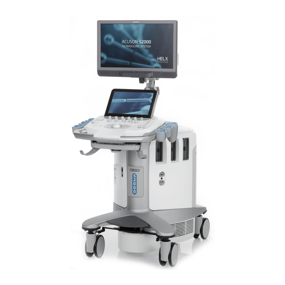
1 I n t r o d u c t i o n System Review Example of the ultrasound system. 1 - 4 I n s t r u c t i o n s f o r U s e... - Page 15 1 I n t r o d u c t i o n User-adjustable high-resolution flat panel monitor with two forward-facing speakers Touch screen For systems without a touch screen, this is the location of the alphanumeric keyboard User-adjustable control panel (height and swivel) Front handle Cable hanger Retractable alphanumeric keyboard (for systems with a touch screen)
- Page 16 1 I n t r o d u c t i o n Example of the ultrasound system, back view. Rear handle Cable hanger Input/output panel with audio and video connections Rear swivel wheel with brake AC tray panel Back panel Storage bin Shelf 1 - 6...
-
Page 17: Control Panel
1 I n t r o d u c t i o n Control Panel The ultrasound imaging system has a combination of keys, rotary knobs, push and rotate controls, and toggle controls. A trackball provides access to on-screen objects. The keys and controls are logically arranged to require a minimum number of hand and eye movements. - Page 18 1 I n t r o d u c t i o n Touch screen with selections for each operating mode's optimization parameters and functions, measurement labels and tools, review selections, and selections for exam types and transducers. You can tap the touch screen to make a selection. Six controls are located on the control panel with corresponding selections on the touch screen.
-
Page 19: Intended Use
The ultrasound system is not intended for ophthalmic use or any ophthalmic application causing the acoustic beam to pass through the eye. ACUSON S1000 Ultrasound System The ACUSON S1000 ultrasound system supports the following applications: Abdominal (Renal) Obstetrics (Fetal Echo) ... -
Page 20: Indications For Use Statement
1 I n t r o d u c t i o n Indications for Use Statement Product Indications for Use Statement ACUSON S1000 The S1000™ ultrasound imaging systems are intended for the following applications: Fetal, Ultrasound System Abdominal, Intraoperative, Pediatric, Small Parts, Transcranial, OB/GYN (useful for... -
Page 21: Acuson S2000 Ultrasound System
1 I n t r o d u c t i o n ACUSON S2000 Ultrasound System The ACUSON S2000 ultrasound system supports the following applications: Abdominal (Renal) Obstetrics (Fetal Echo) Gynecology Small Parts (Breast, Testicle, Thyroid) ... -
Page 22: Acuson S3000 Ultrasound System
1 I n t r o d u c t i o n ACUSON S3000 Ultrasound System The ACUSON S3000 ultrasound system supports the following applications: Abdominal (Renal) Obstetrics (Fetal Echo) Gynecology Small Parts (Breast, Testicle, Thyroid) ... -
Page 23: Transducers And Intended Applications
ACUSON S1000 ultrasound system or the ACUSON S3000 ultrasound system. Transducer Name Operating Frequency Modes of Operation Intended Applications Curved and Linear Array Transducers (Available on the ACUSON S1000 system, ACUSON S2000 system, and ACUSON S3000 system) 2D-mode: 2D, C, D, M Fetal 2.0 MHz–4.5 MHz Abdominal Doppler: 2.0 MHz–3.5 MHz... - Page 24 1 I n t r o d u c t i o n Transducer Name Operating Frequency Modes of Operation Intended Applications Curved and Linear Array Transducers (Available on the ACUSON S1000 system, ACUSON S2000 system, and ACUSON S3000 system) 14L5 2D-mode: 2D, C, D, M Small Organ 6.0 MHz–14.0 MHz ...
- Page 25 1 I n t r o d u c t i o n Transducer Name Operating Frequency Modes of Operation Intended Applications Phased Array Transducers (Available on the ACUSON S1000 system, ACUSON S2000 system, and ACUSON S3000 system) 2D-mode: 2D, C, D, M Fetal 2.0 MHz–4.5 MHz Abdominal Doppler: 2.0 MHz–3.5 MHz...
- Page 26 1 I n t r o d u c t i o n Transducer Name Operating Frequency Modes of Operation Intended Applications Phased Array Transducers (Available on the ACUSON S1000 system, ACUSON S2000 system, and ACUSON S3000 system) V5Ms 2D-mode: 2D, C, D, M, CW Transesophageal 4.0 MHz–7.0 MHz Doppler: 3.5 MHz–4.0 MHz...
- Page 27 1 I n t r o d u c t i o n Transducer Name Operating Frequency Modes of Operation Intended Applications fourSight 4D Transducers (Available on the ACUSON S1000 system, ACUSON S2000 system, and ACUSON S3000 system) 7CF1 2D-mode: 2D, C, D, M Fetal 3.0 MHz–7.0 MHz ...
- Page 28 1 I n t r o d u c t i o n Transducer Name Operating Frequency Modes of Operation Intended Applications Continuous Wave Transducers (Available on the ACUSON S1000 system, ACUSON S2000 system, and ACUSON S3000 system) 2.0 MHz Adult Cephalic Cardiac Peripheral Vessel 5.0 MHz ...
-
Page 29: Image Screen Layout
1 I n t r o d u c t i o n Image Screen Layout The monitor on the ultrasound system displays clinical images together with important operating parameters and patient data. You can hide the thumbnail panel to increase the space available on the screen for the image. For systems without a touch screen, you can also hide the soft key selections and menu located on the left side of the screen. -
Page 30: Sample Image Screens
1 I n t r o d u c t i o n Sample Image Screens Example of a typical image screen. Toolbar buttons. Displays controls for system functions, Trackball status. Indicates the function currently for example, displaying or hiding the menu, accessing assigned to the trackball and the controls adjacent to the the patient browser, and displaying information about trackball. -
Page 31: Safety And Care
Caring for the Ultrasound System ..............24 Daily Checklist ..................... 24 Maintenance ....................25 Repair ....................25 Siemens Authorized Care..............25 Caring for Documentation and Storage Devices .......... 26 Caring for the Battery Pack ................26 Recharging the Battery Pack ..............26 Battery Pack Replacement .............. - Page 32 2 S a f e t y a n d C a r e Caring for Transducers ..................36 Methods for Cleaning and Disinfecting Transducers ........38 Examples of Transducer Components ..........39 Cleaning and Disinfecting Transducers ..........42 Approved List of Cleaners ..............44 Approved List of Disinfectants ..............
-
Page 33: Operating Safety And Environment
2 S a f e t y a n d C a r e Operating Safety and Environment Do not operate the ultrasound imaging system until you fully understand the safety considerations and procedures presented in this manual. System Symbols The table below is provided for your identification of important symbols located on the ultrasound imaging system and transducers: Symbol... - Page 34 2 S a f e t y a n d C a r e Symbol Explanation Control Panel Light or Indicator Light Yellow Indicator Light Status Indicator for DC Power Good (Green) or Green Indicator Light Printer Connection Type BF Defibrillator-proof Patient Connection Type BF Applied Part Type B Patient Connection Continuous Wave Transducer Port...
- Page 35 Community directive 2002/96/EC on waste electrical and electronic equipment (WEEE), amended by directive 2003/108/EC. For collection and disposal of the product, its components, or its accessories, contact your local Siemens representative. Do not dispose of by flushing down lavatory I n s t r u c t i o n s f o r U s e...
- Page 36 2 S a f e t y a n d C a r e Symbol Explanation Pinch hazard. Do not lean against the monitor. Shelf Weight Restriction Brake Engaged Brake Released Direction/Steer Lock Manufacturer's declaration of product compliance with applicable EEC directive(s) and the European notified body DEMKO-Denmark approval mark UL symbol for listing as recognized components for Canada and United States of America...
- Page 37 Location of device manufacturing: Republic of Korea Location of device manufacturing: Japan Location of device manufacturing: Netherlands (System Installierte Volumen Komponente) Identifies the system for product traceability at Siemens Healthcare (Installierte Volumen Komponente) Identifier of selected system components or parts for product...
- Page 38 Explanation Global Trade Item Number Model revision Serial number Quantity of product Siemens model number Device part number Manufacturer country of origin: United States of America Manufacturer country of origin: Republic of Korea Manufacturer country of origin: Japan Manufacturer country of origin: Netherlands...
- Page 39 2 S a f e t y a n d C a r e Symbol Explanation AC (alternating current) voltage source Identifies voltage, frequency, and current rating of system configuration for MAINS. 100V~, 50/60 Hz, 15A maximum draw, 15A MAINS breaker. Identifies voltage, frequency, and current rating of system configuration for MAINS.
- Page 40 2 S a f e t y a n d C a r e Symbol Explanation Weight and size "XXX" represents the weight of the system packaged for shipping "XX" represents the size of the box in inches Do not stack Recycle Storage atmospheric pressure range (example) Storage humidity range (example)
-
Page 41: Labels
2 S a f e t y a n d C a r e Labels System warning label with certification labels Location of labels on the ultrasound system (example). I n s t r u c t i o n s f o r U s e 2 - 1 1... - Page 42 2 S a f e t y a n d C a r e Identification label Country-specific labels Country-specific labels Example of system label. Product name System input power requirement Example of identification label. 2 - 1 2 I n s t r u c t i o n s f o r U s e...
-
Page 43: Biohazard Considerations
WARNING: This equipment is not suitable for intracardiac use or direct cardiac contact. WARNING: For neonatal head imaging, Siemens recommends that you exercise special care during neonatal cephalic scanning to avoid possible damage to the posterior region of the eye. -
Page 44: Note On Fetal Examinations
2 S a f e t y a n d C a r e Note on Fetal Examinations The following recommendation is excerpted from the National Institute of Health in the United States of America. Consensus Statement on the Use of Ultrasound Imaging During Pregnancy, Volume 5, No. -
Page 45: Acoustic Output - Mechanical And Thermal Indices
2 S a f e t y a n d C a r e Acoustic Output — Mechanical and Thermal Indices WARNING: Ultrasound procedures should be used for valid reasons, for the shortest period of time, and at the lowest mechanical/thermal index setting necessary to produce clinically acceptable images. -
Page 46: Mechanical And Thermal Indices
2 S a f e t y a n d C a r e Mechanical and Thermal Indices The ultrasound system displays the Mechanical and Thermal Indices during real-time imaging, in all imaging modes, when the Mechanical Index or the Thermal Indices are equal to or exceed a value of 0.4. -
Page 47: Transmit Power Display
2 S a f e t y a n d C a r e Adjusting the Transmit Power during Contrast Agent Imaging During contrast agent imaging, you can also increase or decrease the transmit power. The transmit power range is from 0.10% to 100% for contrast agent imaging. ●... -
Page 48: Imaging Functions That Change Acoustic Output
2 S a f e t y a n d C a r e Imaging Functions that Change Acoustic Output WARNING: Observe the real-time display of mechanical and thermal indices (MI/TI) at all times. In addition to the adjustment of the transmit power, adjustment of the following imaging functions and/or controls may affect the acoustic output: Automatic Time-out Imaging Mode... -
Page 49: Transducer Surface Temperature Limits
2 S a f e t y a n d C a r e Transducer Surface Temperature Limits The following table provides the maximum surface temperature of the transducers compatible with the system. Maximum surface temperatures are in accordance with IEC 60601-2-37. Maximum Temperature Transducer Still Air... -
Page 50: Electrical Safety
WARNING: Connecting peripheral devices to accessory outlets on the ultrasound system effectively creates a medical electrical system, resulting in a reduced level of safety. WARNING: Do not modify this equipment without authorization from Siemens. 2 - 2 0 I n s t r u c t i o n s f o r U s e... -
Page 51: Level Of Protection Against Electrical Shock - System
Caution: Do not pour any fluid onto the ultrasound system surfaces, as fluid seepage into the electrical circuitry may cause excessive leakage current or system failure. Caution: To ensure proper grounding and leakage current levels, it is the policy of Siemens to have an authorized Siemens representative or Siemens approved third party perform all on-board connections of documentation and storage devices to the ultrasound system. -
Page 52: Defibrillators
2 S a f e t y a n d C a r e Defibrillators WARNING: The ECG function is designed to withstand the effects of defibrillation. However, when possible, disconnect the ECG leads during defibrillation since a malfunction of the safety controls could otherwise result in electrical burns for the patient. -
Page 53: Possible Combinations With Other Equipment
Some on-board peripheral devices must be installed by an authorized Siemens representative or by a Siemens-approved third party. Devices installed by other people will be at the user's risk and may void the system warranty. Maintaining Data Integrity... -
Page 54: Caring For The Ultrasound System
2 S a f e t y a n d C a r e Caring for the Ultrasound System It is the responsibility of the user to verify that the ultrasound system is safe for diagnostic operation on a daily basis. Each day, prior to using the system, perform each of the steps in the Daily Checklist. -
Page 55: Maintenance
To ensure the safety of patients, operators, and third parties, the equipment must be inspected every 24 months, and the replacement of parts is performed as necessary. This maintenance must be performed by a qualified Siemens authorized representative. It is important to inspect the equipment more frequently if it is operated under extraordinary conditions. -
Page 56: Caring For Documentation And Storage Devices
2 S a f e t y a n d C a r e Caring for Documentation and Storage Devices For information on the care of an optional documentation or storage device, refer to the manufacturer's operating instructions that accompanied the device. Caring for the Battery Pack Recharging the Battery Pack See also: Hazardous Substances, p. -
Page 57: Battery Pack Location
2 S a f e t y a n d C a r e Battery Pack Location The battery pack is located under the storage bin cover, within a recess on the right rear panel of the ultrasound system. The storage bin cover must be removed to access the battery pack. Storage bin cover Battery pack location Battery symbol... -
Page 58: Removing The Battery Pack
2 S a f e t y a n d C a r e Removing the Battery Pack Caution: When removing the battery pack, be careful not to pull or otherwise strain the wires in the cable connecting the battery to the ultrasound system because doing so can damage the battery pack and the ultrasound system. -
Page 59: Cleaning And Disinfecting
WARNING: To avoid electric shock and damage to the ultrasound system, power off and unplug the equipment from the AC power outlet before cleaning and disinfecting. WARNING: Disinfectants and cleaning methods listed are recommended by Siemens for compatibility with product materials, not for biological effectiveness. Refer to disinfectant label instructions for guidance on disinfection efficacy and appropriate clinical uses. - Page 60 2 S a f e t y a n d C a r e The following instructions describe cleaning the surface of the ultrasound system, including the trackball and transducer holder. Do This Clean and disinfect the 1. Power off the ultrasound system and unplug the power cord from the power outlet. surface of the ultrasound 2.
- Page 61 2 S a f e t y a n d C a r e Do This Clean and disinfect the gel Caution: To avoid damage to the gel warmer, do not immerse the gel warmer in warmer water or any solution. Note: To facilitate cleaning, remove the cap at the bottom of the gel warmer.
- Page 62 2 S a f e t y a n d C a r e Do This Clean and disinfect the Caution: Do not drop or place foreign objects inside the trackball assembly trackball because doing so may affect the trackball operation and damage the ultrasound system.
-
Page 63: Approved Disinfectant Wipes For The Ultrasound System Surfaces
2 S a f e t y a n d C a r e Approved Disinfectant Wipes for the Ultrasound System Surfaces The following matrix provides a list of approved disinfectant wipes for use on the ultrasound system and surfaces of the listed accessories. Sani-Cloth Sani-Cloth Super... -
Page 64: Cleaning The Air Filter
2 S a f e t y a n d C a r e Cleaning the Air Filter The filter location is marked with the air filter symbol. The ultrasound system has one removable, washable air filter. This air filter must be cleaned regularly to maintain proper system cooling. - Page 65 2 S a f e t y a n d C a r e To remove and clean the back panel air filter: Caution: Do not scrub, stretch, or bend the filter, or apply heat to the filter, as doing so could damage the filter.
-
Page 66: Caring For Transducers
Caution: Transducers are sensitive instruments — irreparable damage may occur if they are dropped, knocked against other objects, cut, or punctured. Do not attempt to repair or alter any part of a transducer, contact your local Siemens representative. Caution: To avoid cable damage, do not roll the ultrasound system over transducer cables. - Page 67 Do not attempt to repair or alter any part of the transducer. Contact your service representative at Siemens immediately if a transducer appears to be damaged or malfunctions in any way. I n s t r u c t i o n s f o r U s e...
-
Page 68: Methods For Cleaning And Disinfecting Transducers
You must observe the required methods for cleaning and disinfecting or cleaning and sterilization before the first use and after each use of a transducer. Siemens defines the methods for cleaning and disinfecting or cleaning and sterilization by classifying the use of the transducer according to the Spaulding Classification scheme observed by the United States Food and Drug Administration (FDA). -
Page 69: Examples Of Transducer Components
2 S a f e t y a n d C a r e Examples of Transducer Components Transducer surface in contact with the patient Handle Strain relief for the transducer Cable Strain relief for the connector Connector Electrical component on the connector Example of transducer components. - Page 70 2 S a f e t y a n d C a r e Transducer surface in contact with the patient (flexible shaft with depth markings, articulating section, and distal tip) Strain relief for the handle Cable Strain relief for the connector Electrical component on the connector Connector...
- Page 71 2 S a f e t y a n d C a r e Immersion Levels Caution: To avoid damage to the transducer, observe the immersion levels indicated for each transducer type. Caution: Do not immerse the label located on the cable of the CW transducer. Note: Transducers meet Ingress Protection level IPX8 of EN 60529 and IEC 60529 to the depth of the immersion line shown in the illustration.
-
Page 72: Cleaning And Disinfecting Transducers
WARNING: To avoid electrical shock and damage to the system, disconnect the transducer prior to cleaning or disinfecting. WARNING: Disinfectants and cleaning methods listed are recommended by Siemens for compatibility with product materials, not for biological effectiveness. Refer to disinfectant label instructions for guidance on disinfection efficacy and appropriate clinical uses. - Page 73 2 S a f e t y a n d C a r e Location in This Manual Required Task Read and understand the biohazard considerations. p. 2-13 Perform the steps in the daily checklist. p. 2-24 Read and understand the cleaning and disinfecting information for the ultrasound system. p.
-
Page 74: Approved List Of Cleaners
2 S a f e t y a n d C a r e Approved List of Cleaners Note: Gigasept FF may discolor the transducer. There is no associated degradation of imaging performance or transducer reliability. You can use Gigasept FF as a cleaner and a disinfectant. ENZOL Gigasept FF Transeptic... -
Page 75: Approved List Of Disinfectants
2 S a f e t y a n d C a r e Approved List of Disinfectants Note: CIDEX OPA and Gigasept FF may discolor the transducer. There is no associated degradation of imaging performance or transducer reliability. You can use Gigasept FF as a cleaner and a disinfectant. -
Page 76: Sterilizing Transducers - 14L5 Sp
2 S a f e t y a n d C a r e Sterilizing Transducers — 14L5 SP Caution: The transducers have been designed and tested to be able to withstand sterilization as recommended by the manufacturer of the sterilization system. Carefully follow the sterilization manufacturer's instructions. -
Page 77: Caring For Transducer Accessories
Ethylene Oxide (EO) methods. Caution: Siemens recommends that you follow all instructions provided by manufacturers of sterile goods (transducer sheaths) to ensure proper handling, storage, and cycling of all sterile goods. -
Page 78: Gel Pad
When the biopsy adapter is transported to a different hospital or clinic or is sent to your Siemens representative for repair, be sure to sterilize it and keep it in the carrying case for transportation to prevent infection. 2 - 4 8... -
Page 79: Cleaning, Disinfecting, And Sterilizing Transducer Accessories
2 S a f e t y a n d C a r e Cleaning, Disinfecting, and Sterilizing Transducer Accessories WARNING: Ensure the accessories for a transducer are properly cleaned, sterilized, or disinfected as appropriate before each use to avoid possible patient contamination. Needle Guide Bracket Kits Needle guide bracket kits are available for specific transducers. - Page 80 2 S a f e t y a n d C a r e CH4-1, C7F2/C5F1, 7CF1, 18L6 HD, 8C3 HD, SG-2, SG-3, SG-4, SG-5 and VF12-4 Bracket Assemblies WARNING: The needle guide is packaged sterile and is a single-use item. Do not use if the packaging indicates signs of tampering or if the expiration date has passed.
-
Page 81: Environmental Protection
For more information, contact your local Siemens representative. To the extent required by local, state, and regional laws and regulations, Siemens has programs for the return of used products. For more information, contact your local Siemens representative. -
Page 82: Recycling Batteries
Recycle batteries according to local, state, and regional laws and regulations. Use a battery collection program available in your country to recycle batteries. To the extent required by local, state, and regional laws and regulations, Siemens will collect and recycle batteries for this product at no charge. Contact your local Siemens representative for battery shipment instructions. -
Page 83: Disposing Of Components And Accessories
2 S a f e t y a n d C a r e Disposing of Components and Accessories WARNING: Observe local, state, and regional laws and regulations for the disposal of the ultrasound system components and accessories. WARNING: Bodily fluids on used needles and needle guides can transmit infectious diseases. To eliminate the possibility of exposing patients, operators, or third parties to hazardous or infectious materials, always dispose of the needle and the needle guide according to local, state, and regional laws and regulations. - Page 84 2 S a f e t y a n d C a r e 2 - 5 4 I n s t r u c t i o n s f o r U s e...
-
Page 85: System Setup
3 System Setup Initial Setup ......................3 Moving the System ..................... 3 Using the Front Brakes .................. 3 Using the Rear Brakes .................. 4 Securing the Monitor ..................5 Prior to the Move ................... 5 During the Move .................... 6 After the Move .................... - Page 86 3 S y s t e m S e t u p 3 - 2 I n s t r u c t i o n s f o r U s e...
-
Page 87: Initial Setup
The ultrasound imaging system is initially unpacked and installed by a Siemens representative. Your Siemens representative will verify the operation of the system. Any transducers, documentation devices, accessories, and options delivered with your system are also connected and installed for you. -
Page 88: Using The Rear Brakes
3 S y s t e m S e t u p Task Procedure To set the front brakes: Press the center section of the front bumper down firmly with your foot until the brakes lock into place. This is the lowest position for the front bumper. To release the front brakes: ... -
Page 89: Securing The Monitor
3 S y s t e m S e t u p Securing the Monitor Flat panel monitor Articulating arm Transport lock Locking pin Example of monitor in locked position. To lock the position of the flat panel monitor for transport: Ensure the directional swivel of the wheels (swivel brakes) on the ultrasound system is locked. -
Page 90: During The Move
3 S y s t e m S e t u p During the Move Caution: When moving the ultrasound system, protect it from environmental changes including: moisture, winds, dirt and dust, and extreme heat or cold exposure. Caution: Avoid moving the ultrasound system on outside surfaces with loose dirt, contaminates, or standing liquids. -
Page 91: Shipping The System
3 S y s t e m S e t u p Shipping the System When shipping the system, perform the following tasks, as appropriate. To prepare the system for shipment over long distances or rough terrain: Repack the system in the factory packaging and crate according to the instructions shown on the container. -
Page 92: Supplying Power To The System
The ultrasound system is powered on and off using the green partial power on/off switch ( ) located on the control panel. Siemens recommends powering off the system every 24 hours to maintain optimal performance. Note: This switch does not completely shut down or disconnect the system from the power mains. -
Page 93: Mobile Quikstart For Portable Studies (Standby)
3 S y s t e m S e t u p Mobile QuikStart for Portable Studies (Standby) The QuikStart feature for portable studies decreases the time required to power the system on or off by using the installed battery to place the ultrasound system in a standby status. The system can maintain the standby status for approximately four hours when the system's power cord is not plugged into the power supply. -
Page 94: Adjusting The Screen Brightness
3 S y s t e m S e t u p Adjusting the Screen Brightness Note: Factory-defined imaging presets were created using default settings of the brightness and contrast controls of the monitor. Adjusting the brightness and tint controls on the monitor may affect the image optimization intended by the factory-defined imaging presets. -
Page 95: Connecting And Disconnecting Transducers
3 S y s t e m S e t u p Connecting and Disconnecting Transducers Caution: Ensure that the system is in freeze before connecting and disconnecting transducers. If a transducer is disconnected before the image is frozen, the system will display an error message. -
Page 96: Array Transducers
3 S y s t e m S e t u p Array Transducers Connect an array transducer to any of the three available array ports. Caution: You must freeze the system before connecting or disconnecting a transducer. Note: When transducer connectors are being attached to or disconnected from the system, resistance may be encountered due to the special shielding material inside the connectors. -
Page 97: Continuous Wave Transducers
3 S y s t e m S e t u p Continuous Wave Transducers Continuous wave transducer port. Caution: You must freeze the system before connecting or disconnecting a CW transducer. To connect a continuous wave transducer: Align the connector key until it fits smoothly into the receptacle. Insert the connector into the system port until it locks in position. -
Page 98: Transducer Cable Management
3 S y s t e m S e t u p Transducer Cable Management WARNING: To avoid injury from tripping over a transducer cable, use the cable hooks on the ultrasound system to keep the transducer cable from contact with the floor. After you have connected and secured a transducer, drape the transducer cable through one of the cable hooks located on the ultrasound system. -
Page 99: Connecting System Accessories
3 S y s t e m S e t u p Connecting System Accessories The ultrasound system has connections for system accessories. Footswitch Attach the optional footswitch connector into the corresponding socket located on the front system panel. Physio Cables ECG connector Aux 1 ECG plug Example of Physio panel. -
Page 100: Gel Warmer
Caution: Do not attempt to repair or alter the gel warmer. Contact your local Siemens service representative immediately if your gel warmer appears to be damaged or malfunctions in any way. - Page 101 Note: A blinking light indicates there is a problem with the device. Check the cable connector on the gel warmer and on the ultrasound system. If you continue to experience a problem with the device, contact your Siemens service representative. Slide the temperature control on the front of the gel warmer to adjust the temperature of the gel warmer.
-
Page 102: Virtual Communication For Remote Assistance
You must remove the camera from the ultrasound system after the conclusion of a remote service session. You can use the optional camera and headset from Siemens for virtual communication with a Siemens service representative. To begin a remote service session: Note: If the camera attachment is not installed on the ultrasound system, inform your service representative. -
Page 103: Connecting The Ultrasound System To A Network
3 S y s t e m S e t u p Connecting the Ultrasound System to a Network The ultrasound system can connect to a local area network (LAN) through a wired or a wireless connection. When both wired and wireless connections are configured and available, the ultrasound system assigns priority to the wired connection. -
Page 104: Network Connection Icons
3 S y s t e m S e t u p To connect the ultrasound system to a network through a wireless connection: Disconnect the network cable from the ultrasound system, if necessary. The ultrasound system connects to the most recently used wireless network, if the wireless network is secured and detected. -
Page 105: System Security
DICOM communication from the system to a DICOM-compatible device. Your Siemens service representative can configure additional security features on your ultrasound system, for example, encrypting the system hard disk and restricting access to the system by requiring a user account and password. -
Page 106: Input/Output Panel Connections
IEC 60601-1. Siemens can only guarantee the performance and safety of the devices listed in the Instructions for Use. If in doubt, consult the Siemens service department or your local Siemens representative. -
Page 107: Connecting Peripheral Equipment
On-board peripheral devices must be installed by an authorized Siemens representative or by a Siemens approved third party. Any use of other devices with the system will be at the user's risk and may void the system warranty. - Page 108 3 S y s t e m S e t u p During normal operation, the ultrasound system is designed to display ultrasound images without noise, artifacts, or distortion that cannot be attributed to physiological effects. Observe the peripheral equipment connections and patient environment shown in the following diagram to support the normal operation of the ultrasound system.
-
Page 109: On-Board Vs. Off-Board Documentation Devices
Doing so will cause the ultrasound system to be out of compliance and may create a safety hazard. Note: Only authorized Siemens representatives are permitted to install documentation devices on-board the ultrasound system. On-board documentation devices must be installed by authorized Siemens representatives. -
Page 110: System Ergonomics
3 S y s t e m S e t u p System Ergonomics You can make the following adjustments to the system: Monitor. You can tilt and swivel the monitor for optimal viewing while scanning. The sides of the monitor provide a general hand hold for tilting and swiveling the monitor. Height and Swivel. -
Page 111: Installing System Updates
The system notifies you that updates are available for installation by displaying an icon at the bottom of the image screen and an installation dialog box when you restart the system. Note: Siemens recommends that you install a system update within one week after the update is downloaded. - Page 112 3 S y s t e m S e t u p 3 - 2 8 I n s t r u c t i o n s f o r U s e...
-
Page 113: Examination Fundamentals
4 Examination Fundamentals Preventing Unauthorized Access ..............3 Logging In to the Ultrasound System ............. 4 Patient Registration .................... 5 Registering or Pre-registering a Patient ............5 Selecting a Scheduled Procedure for Registration ........8 Patient Registration Form Selections ............9 Patient/Procedure Worklist .............. - Page 114 4 E xa m i n a t i o n F u n d a m e n t a l s 4 - 2 I n s t r u c t i o n s f o r U s e...
-
Page 115: Preventing Unauthorized Access
4 E xa m i n a t i o n F u n d a m e n t a l s Preventing Unauthorized Access Prerequisite: A Siemens service representative has activated the security package on the ultrasound system to restrict user access. -
Page 116: Logging In To The Ultrasound System
4 E xa m i n a t i o n F u n d a m e n t a l s Logging In to the Ultrasound System When the security package is activated, all users are required to log in to the ultrasound system prior to use. -
Page 117: Patient Registration
4 E xa m i n a t i o n F u n d a m e n t a l s Patient Registration Note: You can schedule a patient and procedure(s) using a connected Hospital Information System/Radiology Information System (HIS/RIS) server. Use the patient browser to retrieve patient data for scheduled patients. - Page 118 4 E xa m i n a t i o n F u n d a m e n t a l s Do This Retrieve data entered for a Use the system configuration menu to define search options, such as the previous patient or a locations for stored patient data and the type of data to display in the search pre-registered patient...
- Page 119 4 E xa m i n a t i o n F u n d a m e n t a l s Do This Select a transducer from the Transducer list on the patient registration form. Select a transducer during patient registration If a transducer is not selected, the system activates the default transducer for the selected study type if it is connected to the system.
-
Page 120: Selecting A Scheduled Procedure For Registration
4 E xa m i n a t i o n F u n d a m e n t a l s Selecting a Scheduled Procedure for Registration You can select a scheduled procedure step in the patient browser to enter information in the patient registration form. -
Page 121: Patient Registration Form Selections
4 E xa m i n a t i o n F u n d a m e n t a l s Patient Registration Form Selections Use the system configuration menu to customize the layout of the patient registration form. System Config >... -
Page 122: Patient Data
4 E xa m i n a t i o n F u n d a m e n t a l s Patient Data Selection Enter Last Name Patient's last name. If a last name is not entered, then the system generates the name "Unknown." Note: The patient name (first, middle, and last combined) is limited to 60 characters. -
Page 123: Institution
4 E xa m i n a t i o n F u n d a m e n t a l s Institution Note: The system automatically adds a new institution entry to the registration configuration list on the system configuration menu (if the maximum number of entries has not been exceeded). Selection Enter Institution Name... - Page 124 4 E xa m i n a t i o n F u n d a m e n t a l s Selection Description Protocol Lists the eSieScan workflow protocols. A protocol is a pre-defined checklist that guides you through a clinical workflow. Breast Cardiac Vascular...
-
Page 125: History (Ob Or Gyn)
4 E xa m i n a t i o n F u n d a m e n t a l s History (OB or GYN) Selection Enter Date The start date of the patient’s last menstrual period (LMP) or the date of ... -
Page 126: Changing The Exam, Transducer, Protocol, Or Patient Information
4 E xa m i n a t i o n F u n d a m e n t a l s Changing the Exam, Transducer, Protocol, or Patient Information During an examination, you can correct patient registration information or select a different exam type, protocol, or transducer. - Page 127 4 E xa m i n a t i o n F u n d a m e n t a l s Do This Begin a new study during an 1. Display the patient registration form. examination ● Press PATIENT on the control panel. ○...
-
Page 128: Imaging Overview
4 E xa m i n a t i o n F u n d a m e n t a l s Imaging Overview You can activate each mode of operation using the mode controls located on the control panel. Mode-specific menus and selections display during imaging. - Page 129 4 E xa m i n a t i o n F u n d a m e n t a l s Example of 2D-mode with M-mode imaging. Focal zone markers M-mode cursor M-mode sweep with depth scale Depth Time scale Heart rate I n s t r u c t i o n s f o r U s e...
-
Page 130: Priority Mode
4 E xa m i n a t i o n F u n d a m e n t a l s Priority Mode A mode must have visibility or priority over any other activated modes for you to adjust the controls or make menu selections for that mode. -
Page 131: Color Flow Overview
4 E xa m i n a t i o n F u n d a m e n t a l s Color Flow Overview During Color imaging, the system applies color to indicate velocities of blood flow in a defined region of interest (ROI) within a 2D image. -
Page 132: Doppler
4 E xa m i n a t i o n F u n d a m e n t a l s Doppler Doppler displays a 2D image and a Doppler spectrum. The cursor represents the acoustic line along which the sample volume or the Doppler gate is placed for gathering Doppler information. The system supports both pulsed wave and continuous wave Doppler. - Page 133 4 E xa m i n a t i o n F u n d a m e n t a l s Settings Example Parameter Transducer name Abdomen Exam General Image optimization preset for the active priority mode. ...
- Page 134 4 E xa m i n a t i o n F u n d a m e n t a l s Example Parameter 9dB DR65 Gain / dynamic range CTI1 Optimization setting applied during Custom Tissue Imaging CPS 0 db Gain during contrast agent imaging ASC 3 Level of SieClear or Advanced SieClear spatial compounding...
-
Page 135: Working With Mode-Specific Menus
4 E xa m i n a t i o n F u n d a m e n t a l s Doppler Settings Example Parameter Pulsed wave Doppler (PW) or continuous wave Doppler (CW) 5.3 MHz Transmit frequency 68 dB DR 55 Gain / dynamic range Map F... - Page 136 4 E xa m i n a t i o n F u n d a m e n t a l s Do This 1. Rotate MENU to highlight a menu heading, such as Protocol. Expand or hide menu selections using MENU 2.
-
Page 137: Performing Measurements And Calculations
4 E xa m i n a t i o n F u n d a m e n t a l s Performing Measurements and Calculations The measurement function includes the measurements and calculations available for each exam type and imaging mode. You can use the measurement function during a patient examination or with stored images. -
Page 138: Creating And Viewing Thumbnails
4 E xa m i n a t i o n F u n d a m e n t a l s Creating and Viewing Thumbnails Thumbnails are reduced-size representations of clips, volumes, or a single frame. The system automatically creates thumbnails when you complete a store operation. - Page 139 4 E xa m i n a t i o n F u n d a m e n t a l s Do This Control Tool Tip Copy a thumbnail to a film Copy to Note: You can select multiple consecutive or non-consecutive sheet Film thumbnails.
-
Page 140: Recording And Playing Back With A Digital Video Recorder (Dvr)
The ultrasound system also displays DVR status messages on the image menu and in the list of imaging parameters. Note: The DVR supports only BD-R and BD-RE disk media. Siemens has qualified media only from Panasonic and TDK. - Page 141 4 E xa m i n a t i o n F u n d a m e n t a l s To play back a recorded patient study: Prerequisite: The media with the recorded study is in the DVR and the DVR is powered on before powering on the ultrasound system.
-
Page 142: Examination Completion
4 E xa m i n a t i o n F u n d a m e n t a l s Examination Completion You can end an examination from the review screen or the patient registration screen. WARNING: If the Nuance data transfer feature is enabled, the ultrasound system transfers measured results from the patient report to the configured destination device when you end an exam. -
Page 143: Transducer Accessories And Biopsy
5 Transducer Accessories and Biopsy Transducer Accessories ..................3 Transducer Sheaths ..................5 General Information — Sheaths ............. 5 Application — Sheaths ................5 Disposal — Sheaths ................5 Gel Pad......................6 Preparation for Use ................6 Needle Guide Brackets .................. 6 EC-1 Needle Guide Bracket Kit .............. - Page 144 5 T r a n s d u c e r A c c e s s o r i e s a n d B i o p s y 5 - 2 I n s t r u c t i o n s f o r U s e...
-
Page 145: Transducer Accessories
5 T r a n s d u c e r A c c e s s o r i e s a n d B i o p s y Transducer Accessories WARNING: Before using the transducer accessories, you must read and understand the Caring for Transducer Accessories section of Chapter 2, Instructions for Use. - Page 146 5 T r a n s d u c e r A c c e s s o r i e s a n d B i o p s y Accessory Curved Array Linear Array Phased Array Endocavity fourSight 4D Needle Guide Bracket EC9-4 Kits, EC-1...
-
Page 147: Transducer Sheaths
5 T r a n s d u c e r A c c e s s o r i e s a n d B i o p s y Transducer Sheaths Siemens makes every effort to manufacture safe and effective transducers. You must take all necessary precautions to eliminate the possibility of exposing patients, operators, or third parties to hazardous or infectious materials. -
Page 148: Gel Pad
Needle Guide Brackets WARNING: Percutaneous procedures always involve heightened risk to the patient and to the operator handling biopsy needle guides. Clinicians using Siemens recommended biopsy devices under ultrasound guidance should be trained and must observe proper needle insertion sequencing with the needle guide in order to avoid undue discomfort and unnecessary risk and injury to the patient. -
Page 149: Ec-1 Needle Guide Bracket Kit
5 T r a n s d u c e r A c c e s s o r i e s a n d B i o p s y EC-1 Needle Guide Bracket Kit The EC-1 Needle Guide Bracket Kit consists of a biopsy guide cover, three biopsy guide plates (15G/16G, 17G/18G, 19G/20G/21G), an operation manual, and a carrying case. - Page 150 5 T r a n s d u c e r A c c e s s o r i e s a n d B i o p s y To attach the needle guide to the transducer: WARNING: Care must be taken to ensure that the needle guide is properly positioned. When properly positioned, the bracket will cover the colored ring on the transducer handle and the hook will be firmly against the transducer tip.
- Page 151 5 T r a n s d u c e r A c c e s s o r i e s a n d B i o p s y Detachment Hold the biopsy adapter firmly on the sides and pull it upwards to remove it from the transducer.
-
Page 152: Biopsy (Puncture) Guideline Function
Biopsy (Puncture) Guideline Function WARNING: Percutaneous procedures always involve heightened risk to the patient and to the operator handling biopsy needle guides. Clinicians using Siemens recommended biopsy devices under ultrasound guidance should be trained and must observe proper needle insertion sequencing with the needle guide in order to avoid undue discomfort and unnecessary risk and injury to the patient. -
Page 153: System Biopsy Safeguards
5 T r a n s d u c e r A c c e s s o r i e s a n d B i o p s y System Biopsy Safeguards WARNING: To reduce the risk of injury to the patient, conduct a biopsy procedure during real-time imaging. -
Page 154: Needle Path Verification
WARNING: Do not use a needle guide if the path of the needle is not accurately indicated by the on-screen guidelines. The path of the needle must display within the guideline. Contact your Siemens service representative if the needle path is not accurately indicated. Attach the needle guide to the transducer. -
Page 155: Transesophageal Transducer
6 Transesophageal Transducer Introduction to the Transesophageal Transducers ......... 3 About the V5Ms Transducer ................4 Transducer Articulation Controls (V5Ms) ............5 Array Rotation Control (V5Ms) ............... 5 Flex Controls (V5Ms) ................6 Friction Brakes (V5Ms) ................7 About the V7M Transducer ................9 Transducer Articulation Controls (V7M) ............ - Page 156 6 T r a n s e s o p h a g e a l T r a n s d u c e r Caring for the Transesophageal Transducer ..........30 Cleaning and Storage .................. 30 Approved Cleaning and Disinfection Agents for the Transesophageal Transducer ...................
-
Page 157: Introduction To The Transesophageal Transducers
6 T r a n s e s o p h a g e a l T r a n s d u c e r Introduction to the Transesophageal Transducers WARNING: Do not use this transducer unless you are thoroughly trained in transesophageal echocardiography and are familiar with the orientation of cardiac images obtained through a TEE procedure. -
Page 158: About The V5Ms Transducer
6 T r a n s e s o p h a g e a l T r a n s d u c e r About the V5Ms Transducer The V5Ms is a multi-frequency, multi-plane, phased sector array transducer. The V5Ms transducer supports the following modes: 2D-mode ... -
Page 159: Transducer Articulation Controls (V5Ms)
6 T r a n s e s o p h a g e a l T r a n s d u c e r Transducer Articulation Controls (V5Ms) Caution: Do not use your hands or fingers to bend or manipulate the articulating section of the transesophageal transducer. -
Page 160: Flex Controls (V5Ms)
6 T r a n s e s o p h a g e a l T r a n s d u c e r Flex Controls (V5Ms) The flex controls manipulate the movement of the distal tip. Example of flex controls located on the handle of the V5Ms transducer. Anterior/Posterior Deflection For anterior deflection (anteflexion) of the distal tip, rotate the anterior/posterior flex control toward the A marking to move the tip anteriorly. -
Page 161: Friction Brakes (V5Ms)
6 T r a n s e s o p h a g e a l T r a n s d u c e r Friction Brakes (V5Ms) The friction brakes lock the deflection positions of the distal tip. When the brakes are engaged, you can change the imaging scan plane without losing acoustical contact. - Page 162 6 T r a n s e s o p h a g e a l T r a n s d u c e r Example of V5Ms transducer with locked/unlocked icons. Brake for Left/Right flex control is in the locked position.
-
Page 163: About The V7M Transducer
6 T r a n s e s o p h a g e a l T r a n s d u c e r About the V7M Transducer The V7M is a multi-frequency, multi-plane, phased sector array transducer. The V7M transducer supports the following modes: 2D-mode ... -
Page 164: Transducer Articulation Controls (V7M)
6 T r a n s e s o p h a g e a l T r a n s d u c e r Transducer Articulation Controls (V7M) Caution: Do not use your hands or fingers to bend or manipulate the articulating section of the transesophageal transducer. -
Page 165: Friction Brake (V7M)
6 T r a n s e s o p h a g e a l T r a n s d u c e r Friction Brake (V7M) The friction brake locks the deflection position of the distal tip. When the brake is engaged, you can change the imaging scan plane without losing acoustical contact. -
Page 166: Flex Control (V7M)
6 T r a n s e s o p h a g e a l T r a n s d u c e r Flex Control (V7M) The flex control manipulates the movement of the distal tip. Anterior/Posterior Deflection For anterior deflection (anteflexion) of the distal tip, rotate the flex control clockwise. -
Page 167: Preparation For Use
90° to 120° upward and 60° to 90° downward. If the up/down deflection exceeds the maximum deflection angle range, do not use the transesophageal transducer. The distal tip could fold over in the esophagus, causing possible patient injury. Contact your local Siemens representative. -
Page 168: Inspecting The Transducer
For additional information in the U.S.A., refer to FDA Medical Alert MDA91-1. For greatest patient and operator safety, cover a transducer with a transducer sheath. Siemens recommends that you use market-cleared transducer sheaths specifically designed for TEE applications. -
Page 169: Electrical Safety Considerations
6 T r a n s e s o p h a g e a l T r a n s d u c e r Electrical Safety Considerations For safe use of this device, ensure an electrical safety procedure is in place for periodically inspecting the grounding system in the examination area and that this procedure is performed routinely. -
Page 170: Punctures Or Cracks
If punctures or cracks in the outer layer of the transducer are observed, contact your local Siemens representative. Electrosurgical Units WARNING: Use only isolated output electrosurgical units with the transesophageal transducer and disconnect the transducer when it is not in use. -
Page 171: Exam Procedures
6 T r a n s e s o p h a g e a l T r a n s d u c e r Exam Procedures WARNING: (V5Ms only) Ensure that the friction brakes are unlocked and the flex controls are in the neutral alignment position when you insert or withdraw the transducer. - Page 172 6 T r a n s e s o p h a g e a l T r a n s d u c e r Exam Procedures (V7M) To use the V7M transducer during a transesophageal echocardiogram: Remove dentures, if present, and place them in a protected area until after the procedure. Place a transducer sheath on the transducer, if needed.
-
Page 173: Imaging With The V5Ms Transducer
6 T r a n s e s o p h a g e a l T r a n s d u c e r Imaging with the V5Ms Transducer When you connect a transesophageal transducer to the system, the system displays a transducer-specific message. -
Page 174: Changing The Imaging Scan Plane (V5Ms)
6 T r a n s e s o p h a g e a l T r a n s d u c e r Changing the Imaging Scan Plane (V5Ms) You can change the imaging plane of the V5Ms transducer by using the array rotation control to rotate the transducer crystal within the distal tip of the transducer in a 0°... -
Page 175: Temperature Controls And Safeguards (V5Ms)
6 T r a n s e s o p h a g e a l T r a n s d u c e r Temperature Controls and Safeguards (V5Ms) WARNING: Disconnect the transducer if the system displays the message indicating that the maximum thermal limit is exceeded. -
Page 176: Managing The Lens Surface Temperature (V5Ms)
6 T r a n s e s o p h a g e a l T r a n s d u c e r Managing the Lens Surface Temperature (V5Ms) You can reduce the acoustic output to lower the lens surface temperature. See also: Imaging Functions that Change Acoustic Output, Safety and Care, Chapter 2, Instructions for Use To reduce the acoustic output:... -
Page 177: Temperature Sensor Failure (V5Ms)
Remove the transducer from the patient. Failure to disconnect and remove a transesophageal transducer with faulty temperature sensor can burn the patient's esophagus. Contact your Siemens service representative. Follow the instructions included in the on-screen message if the system detects a temperature... -
Page 178: Imaging With The V7M Transducer
6 T r a n s e s o p h a g e a l T r a n s d u c e r Imaging with the V7M Transducer WARNING: You must be aware of the patient's core temperature and select the appropriate patient temperature setting when using the V7M transducer. -
Page 179: Changing The Imaging Scan Plane (V7M)
6 T r a n s e s o p h a g e a l T r a n s d u c e r Changing the Imaging Scan Plane (V7M) You can change the imaging plane of the V7M transducer by rotating the array rotation control. As the array orientation changes, the on-screen scan plane icon updates to indicate the relative direction of the array and the numerical value of the rotation angle. -
Page 180: Selecting An Estimated Patient Temperature Setting (V7M)
6 T r a n s e s o p h a g e a l T r a n s d u c e r Selecting an Estimated Patient Temperature Setting (V7M) WARNING: The V7M transesophageal transducer can exceed 43°C in the event of a system malfunction, which can harm the patient. -
Page 181: Temperature Controls And Safeguards (V7M)
6 T r a n s e s o p h a g e a l T r a n s d u c e r Temperature Controls and Safeguards (V7M) WARNING: Disconnect the transducer if the system displays the message indicating that the maximum thermal limit is exceeded. -
Page 182: Managing The Lens Surface Temperature (V7M)
6 T r a n s e s o p h a g e a l T r a n s d u c e r Managing the Lens Surface Temperature (V7M) You can reduce the acoustic output to lower the lens surface temperature. See also: Imaging Functions that Change Acoustic Output, Safety and Care, Chapter 2, Instructions for Use To reduce the acoustic output:... -
Page 183: Temperature Sensor Failure (V7M)
Remove the transducer from the patient. Failure to disconnect and remove a transesophageal transducer with faulty temperature sensor can burn the patient's esophagus. Contact your Siemens service representative. Follow the instructions included in the on-screen message if the system detects a temperature... -
Page 184: Caring For The Transesophageal Transducer
WARNING: The use of any disinfectants other than those specified here may damage the transducer and, as a result, may create electrical hazards for patients and/or users. WARNING: Disinfectants and cleaning methods listed are recommended by Siemens for compatibility with product materials, not for biological effectiveness. Refer to disinfectant label instructions for guidance on disinfection efficacy and appropriate clinical uses. -
Page 185: Cleaning And Disinfecting The Transducer
6 T r a n s e s o p h a g e a l T r a n s d u c e r Cleaning and Disinfecting the Transducer WARNING: To avoid electrical shock and damage to the system, disconnect the transducer prior to cleaning or disinfecting. - Page 186 6 T r a n s e s o p h a g e a l T r a n s d u c e r To clean the transesophageal transducer: Disconnect and remove the transducer from the ultrasound system. While wearing protective gloves, remove the transducer sheath, if any.
- Page 187 6 T r a n s e s o p h a g e a l T r a n s d u c e r V5Ms: Submerge only to the 100-cm mark. V7M: Submerge only to the 70-cm mark. To disinfect the transesophageal transducer: Note: If using a disinfectant wipe, thoroughly wipe the distal tip and flexible shaft of the transducer.
-
Page 188: Storing And Handling
Service and Repair Do not attempt to repair or alter any part of the transesophageal transducer. Contact your local Siemens service representative office immediately if your transducer appears to be damaged or malfunctions in any way. 6 - 3 4... -
Page 189: Preventing Injury And Equipment Damage
6 T r a n s e s o p h a g e a l T r a n s d u c e r Preventing Injury and Equipment Damage Following the preventive measures outlined below will help ensure patient safety. Potential Harm to Preventive Measure Problem... - Page 190 6 T r a n s e s o p h a g e a l T r a n s d u c e r Potential Harm to Patient/Potential Damage Preventive Measure Problem Do not use the transesophageal transducer Esophageal Varices Excessive bleeding if a patient has esophageal varices or...
-
Page 191: V5Ms Transducer Technical Description
6 T r a n s e s o p h a g e a l T r a n s d u c e r V5Ms Transducer Technical Description Transducer Type: Phased Array, multiplane Elements: Array Rotation Angle: 0° to 180° Distal Tip Articulation: 120°... - Page 192 6 T r a n s e s o p h a g e a l T r a n s d u c e r Measurement Accuracy Rotation angle of the transducer array: ≤3° Temperature: Temperature Accuracy >41°C 40.1 ≤ 41°C >=41°C 40.1 ≤...
-
Page 193: V7M Transducer Technical Description
6 T r a n s e s o p h a g e a l T r a n s d u c e r V7M Transducer Technical Description Transducer Type: Phased Array, multiplane Elements: Range of Array Rotation Angle: -12°... - Page 194 6 T r a n s e s o p h a g e a l T r a n s d u c e r Measurement Accuracy Rotation angle of the transducer array: Temperature: Temperature Accuracy 40°C -0.6°C to +0.4°C 41°C -0.5°C to +0.5°C 42°C...
-
Page 195: Specialty Transducers
7 Specialty Transducers 9EVF4 Transducer ....................3 Transducer Markings ..................3 Imaging with the 9EVF4 Transducer ............. 4 Technical Data ....................5 I n s t r u c t i o n s f o r U s e 7 - 1... - Page 196 7 S p e c i a l t y T r a n s d u c e r s 7 - 2 I n s t r u c t i o n s f o r U s e...
-
Page 197: 9Evf4 Transducer
7 S p e c i a l t y T r a n s d u c e r s 9EVF4 Transducer WARNING: Before attempting to use endocavity transducers, you should be trained in ultrasonography and endocavity scanning techniques, and you should be thoroughly familiar with the safe operation of the ultrasound imaging system. -
Page 198: Imaging With The 9Evf4 Transducer
7 S p e c i a l t y T r a n s d u c e r s Imaging with the 9EVF4 Transducer The 9EVF4 transducer supports all of the functions and controls that are available in 2D-mode, M-mode, Color, Power, Pulsed Doppler, and during volume acquisition. -
Page 199: Technical Data
7 S p e c i a l t y T r a n s d u c e r s Technical Data Transducer type: Mechanically-driven curved array Number of Elements: Frequency range: 2D-Mode 4.0 MHz, 7.0 MHz, 9.0 MHz Doppler and Color 4.0 MHz, 5.5 MHz, 7.5 MHz 5.0 MHz, 7.0 MHz, 9.0 MHz... - Page 200 7 S p e c i a l t y T r a n s d u c e r s 7 - 6 I n s t r u c t i o n s f o r U s e...
-
Page 201: Physiologic Function
8 Physiologic Function Physiologic Function ..................3 Activating the ECG Feature ................4 ECG Troubleshooting Guide ................6 I n s t r u c t i o n s f o r U s e 8 - 1... - Page 202 8 P h y s i o l o g i c F u n c t i o n 8 - 2 I n s t r u c t i o n s f o r U s e...
- Page 203 8 P h y s i o l o g i c F u n c t i o n Physiologic Function WARNING: Use ECG for timing purposes only. It is not intended for diagnostic usage or patient monitoring. WARNING: Do not use the ECG feature in conjunction with electrosurgery or diathermy equipment.
- Page 204 8 P h y s i o l o g i c F u n c t i o n Activating the ECG Feature Note: The ECG inputs are defibrillation proof. However, in the event of defibrillation while using the ECG function, the ECG inputs may become saturated (overloaded).
- Page 205 8 P h y s i o l o g i c F u n c t i o n To adjust the ECG trace: ● Select More and then select Physio. ○ For systems without a touch screen, press Physio on the keyboard. Do this Adjust the wave (Available only when Manual Gain is enabled on the system configuration menu)
- Page 206 8 P h y s i o l o g i c F u n c t i o n Do this Select ECG. Display or hide a trace on an image 1. Enable the first ECG trigger. Enable trigger markers at specific points in the ●...
- Page 207 9 eSieFusion Imaging eSieFusion Overview ..................3 Terminology Used in This Chapter ..............5 Activating and Deactivating eSieFusion ............6 Quality Indicators ..................7 Loading the Reference Data ................8 eSieFusion Functions ..................8 eSieFusion Navigator ..................9 eSieFusion Navigator Controls ............... 9 Working with eSieFusion ................
- Page 208 9 e S i e F u s i o n I m a g i n g 9 - 2 I n s t r u c t i o n s f o r U s e...
-
Page 209: Esiefusion Imaging
9 e S i e F u s i o n I m a g i n g eSieFusion Overview WARNING: This feature uses reference data collected using other imaging modalities. Variability in system performance, operator technique, patient characteristics, patient movement, and other factors may affect image alignment and sensor tracking data. - Page 210 9 e S i e F u s i o n I m a g i n g Example of eSieFusion screen during real-time imaging. Blended image Tracking quality indicator Orientation indicator Navigator For systems without a touch screen, the system displays the eSieFusion menu selections on the left side of the image screen, above the Navigator.
-
Page 211: Terminology Used In This Chapter
9 e S i e F u s i o n I m a g i n g Terminology Used in This Chapter Term Definition blended image An overlay of reference data on a real-time ultrasound image. electronics unit Component of the tracking system that provides connections to the transmitter, the transducer sensors, and the needle sensor. -
Page 212: Activating And Deactivating Esiefusion
9 e S i e F u s i o n I m a g i n g Activating and Deactivating eSieFusion The tracking system must be powered on and a transmitter and at least one transducer sensor must be connected to the electronics unit before you activate eSieFusion. See also: Setting up the Tracking System for eSieFusion Imaging, p. -
Page 213: Quality Indicators
9 e S i e F u s i o n I m a g i n g Quality Indicators After the tracking system is initialized, the ultrasound system displays graphical tracking quality indicators for the transducer sensor and the needle tracking sensor. The indicator displays a green bar across the width of the indicator when tracking quality is high. -
Page 214: Loading The Reference Data
9 e S i e F u s i o n I m a g i n g Loading the Reference Data You must import reference data to the local database (system hard drive) before you load reference data to an exam. See also: Importing Patient Data, Patient Data Management, Chapter C2, Features and Applications Reference To load reference data to eSieFusion:... -
Page 215: Esiefusion Navigator
9 e S i e F u s i o n I m a g i n g eSieFusion Navigator The Navigator lists all planning data and alignments created for the displayed image. Planning data includes landmarks, segmentations, and needle paths. Each time you create planning data, the system displays a unique marker on the image and updates the Navigator with a corresponding entry. - Page 216 9 e S i e F u s i o n I m a g i n g Do this Rename an entry in the 1. Double-click the entry text in the list. Navigator 2. Enter the new name in the text box and then press Enter on the keyboard. The system updates the name in the Navigator and on the image.
-
Page 217: Working With Esiefusion
9 e S i e F u s i o n I m a g i n g Working with eSieFusion Do this Change the display format (Available only when a blended image is displayed. Biopsy controls are available in 1:1, 2:1 and 1:3 display formats.) 1. - Page 218 9 e S i e F u s i o n I m a g i n g Do this Position a landmark (Not available during system freeze or image alignment) Note: If you position landmarks on the ultrasound image before you load the reference data, the system deletes the landmarks when the reference data is loaded.
- Page 219 9 e S i e F u s i o n I m a g i n g Do this Apply predefined optimization (Available only during planning) settings to the displayed Note: If the volume quadrant is selected, the system applies the setting to the reference data volume data.
-
Page 220: Real-Time Imaging
9 e S i e F u s i o n I m a g i n g Real-time Imaging Use the Scan tools to perform real-time imaging before you load the reference data. After the reference data has been aligned with the ultrasound image, you can capture additional images and clips of the blended image. -
Page 221: Interventional Procedures
Interventional Procedures WARNING: Percutaneous procedures always involve heightened risk to the patient and to the operator handling biopsy needle guides. Clinicians using Siemens recommended biopsy devices under ultrasound guidance should be trained and must observe proper needle insertion sequencing with the needle guide in order to avoid undue discomfort and unnecessary risk and injury to the patient. - Page 222 9 e S i e F u s i o n I m a g i n g To enable or disable tracking of the needle tip (green circle), select Needle Tip Graphics. Example of the eSieFusion screen with needle tracking. Indicates the position of the needle (solid line) Indicates 5 mm on each side of the position of the needle (dotted line) Indicates that the needle tip position is outside the image plane...
-
Page 223: Planning Data
9 e S i e F u s i o n I m a g i n g Planning Data You can create landmarks and segmentations on the reference data to identify areas of interest. You can also draw planned needle paths for use during an interventional procedure. An on-screen indicator identifies the orientation of the patient. - Page 224 9 e S i e F u s i o n I m a g i n g To create planning data on the reference data: Prerequisite: If you manually entered the patient name, patient ID, date of birth, and gender on the patient registration form, the entries are case sensitive and must match the corresponding information for the reference data.
- Page 225 9 e S i e F u s i o n I m a g i n g Do this Pan the volume a. Activate the pan function. ● Select Pan. ○ For systems without a touch screen, press NEXT to select Pan. b.
- Page 226 9 e S i e F u s i o n I m a g i n g Do this Identify an area of interest by a. Activate the seed placement tool. positioning seeds ● Select Seed Segmentation. ○ For systems without a touch screen, click Seed Segmentation on the image menu.
-
Page 227: Image Alignment
9 e S i e F u s i o n I m a g i n g Image Alignment eSieFusion provides tools to align the reference data and an ultrasound image. An on-screen indicator identifies the orientation of the reference data during alignment. See also: Planning Data, p. -
Page 228: Adjusting The Image Alignment
9 e S i e F u s i o n I m a g i n g Adjusting the Image Alignment You can use the alignment tools in any combination to perform fine adjustments of the image alignment with the reference data. Do this Acquire an ultrasound clip and (Available only for CT reference data) - Page 229 9 e S i e F u s i o n I m a g i n g Do this Align the ultrasound image and 1. Activate the point function. the reference data using ● Select Point. corresponding points ○ For systems without a touch screen, press PRIORITY to select Point. The system displays the reference data and ultrasound image in a side-by-side format.
-
Page 230: Troubleshooting
9 e S i e F u s i o n I m a g i n g Troubleshooting Symptom Possible Cause Recommend Action System indicates poor The tracking sensor is not properly Verify that the sensor has been transducer tracking quality attached to the transducer. -
Page 231: Setting Up The Tracking System For Esiefusion Imaging
Connecting the Electronics Unit to the Ultrasound System Note: The electronics unit must be installed by an authorized Siemens representative or by a Siemens-approved third party. The electronics unit must be connected to a USB port on the input/output panel of the ultrasound system. -
Page 232: Connecting The Transmitter
9 e S i e F u s i o n I m a g i n g Connecting the Transmitter Connect the transmitter cable to the connector on the front of the electronics unit. Example of the electronics unit for the trakSTAR2 tracking system, front view. Connection for the transmitter Status indicator Ports for connecting transducer sensors... -
Page 233: Attaching The Sensors To The Electronics Unit
9 e S i e F u s i o n I m a g i n g Attaching the Sensors to the Electronics Unit Ports for sensors on the electronics unit are associated with a specific transducer port on the ultrasound system. -
Page 234: Maintenance, Cleaning, And Care For Esiefusion Imaging
9 e S i e F u s i o n I m a g i n g Maintenance, Cleaning, and Care for eSieFusion Imaging Daily Checklist Note: In addition to the daily checklist for eSieFusion, you must also perform each of the steps in the Daily Checklist for the ultrasound system. - Page 235 10 Virtual Touch Applications Acoustic Radiation Force Impulse Technology ..........3 Virtual Touch Imaging ..................4 Virtual Touch Imaging Measurements ............5 Virtual Touch Quantification ................6 Virtual Touch Quantification Measurements ..........8 Virtual Touch Quantification Patient Report ..........10 Virtual Touch Quantification Scanning Technique Hints ......
- Page 236 1 0 V i r t u a l T o u c h A p p l i c a t i o n s 1 0 - 2 I n s t r u c t i o n s f o r U s e...
-
Page 237: Virtual Touch Applications
1 0 V i r t u a l T o u c h A p p l i c a t i o n s Acoustic Radiation Force Impulse Technology WARNING: To prevent the possibility of inadvertently heating tissue, avoid repeated image acquisitions near the interface of bone and tissue within a short period of time. -
Page 238: Virtual Touch Imaging
1 0 V i r t u a l T o u c h A p p l i c a t i o n s Virtual Touch Imaging Use Virtual Touch imaging to qualitatively visualize tissue stiffness for a selected region of interest. -
Page 239: Virtual Touch Imaging Measurements
1 0 V i r t u a l T o u c h A p p l i c a t i o n s Do This Reposition or resize the 1. Activate the positioning or sizing function: region of interest (ROI) ●... -
Page 240: Virtual Touch Quantification
1 0 V i r t u a l T o u c h A p p l i c a t i o n s Virtual Touch Quantification Use Virtual Touch quantification to measure tissue for a selected region of interest as shear velocity (Vs) or elasticity (E). - Page 241 1 0 V i r t u a l T o u c h A p p l i c a t i o n s Do This Reposition the region of Roll the trackball to reposition the ROI. interest The software restricts the depth of the ROI.
-
Page 242: Virtual Touch Quantification Measurements
1 0 V i r t u a l T o u c h A p p l i c a t i o n s Virtual Touch Quantification Measurements Virtual Touch quantification provides a set of shear velocity and elasticity measurement labels for abdomen exams: Up to four sites for generic locations ... - Page 243 1 0 V i r t u a l T o u c h A p p l i c a t i o n s To measure then label shear velocity or elasticity: Press UPDATE. The system displays the measurement in the measured results. Display the liver assessment measurement labels: ●...
-
Page 244: Virtual Touch Quantification Patient Report
1 0 V i r t u a l T o u c h A p p l i c a t i o n s Virtual Touch Quantification Patient Report When you have made Virtual Touch quantification measurements, the abdomen patient report lists measurements for each liver assessment measurement label. - Page 245 1 0 V i r t u a l T o u c h A p p l i c a t i o n s Example of abdomen patient report with location of Virtual Touch quantification measurements and liver assessment data. Measurement labels Shear velocity or elasticity and depth measurements associated with the selected labels Mean, median, standard deviation, interquartile range, and the ratio of the interquartile range to the...
-
Page 246: Virtual Touch Quantification Scanning Technique Hints
When frequent "x.xx" results are encountered in focal lesions, Siemens recommends evaluating the elevated shear wave velocities in the periphery of the lesion. - Page 247 1 0 V i r t u a l T o u c h A p p l i c a t i o n s In general, use a transducer angle of 90 degrees to the skin surface for the highest ...
-
Page 248: Shear Wave Velocity And Elasticity Measurements In Liver Assessment
1 0 V i r t u a l T o u c h A p p l i c a t i o n s Shear Wave Velocity and Elasticity Measurements in Liver Assessment Virtual Touch quantification can provide a reliable measure of shear wave velocity and elasticity in the liver when proper technique is used. -
Page 249: Virtual Touch Iq
Caution: In breast applications of Virtual Touch IQ, shear wave imaging may have limitations in adequately visualizing regions of very high stiffness, for example, in certain breast cancers. Siemens recommends using the Quality image display setting to verify that the shear wave velocity and elasticity image represents adequate shear wave formation. Shear wave velocity and elasticity measurements should be made only in regions with high shear wave quality, represented in green when the Quality image display setting is selected. - Page 250 1 0 V i r t u a l T o u c h A p p l i c a t i o n s In either full-screen or dual-screen format, you can apply one of the following image display settings to the shear wave velocity and elasticity data: Velocity or Elasticity, Quality, Time, or Displacement.
- Page 251 1 0 V i r t u a l T o u c h A p p l i c a t i o n s Example of Virtual Touch IQ screen. Virtual Touch IQ region of interest Measured results for shear wave velocity or elasticity. If you perform a measurement within the region of interest (ROI) that exceeds the current maximum velocity setting, the measured results display HIGH for the shear velocity value.
- Page 252 1 0 V i r t u a l T o u c h A p p l i c a t i o n s To activate Virtual Touch IQ: During 2D-mode imaging, select the control assigned to activating the feature: ●...
-
Page 253: Virtual Touch Iq Measurements
1 0 V i r t u a l T o u c h A p p l i c a t i o n s Virtual Touch IQ Measurements You can measure the shear wave velocity or elasticity anywhere within the region of interest. You can perform multiple measurements on a single acquisition. - Page 254 1 0 V i r t u a l T o u c h A p p l i c a t i o n s Do This Adjust the range of velocities 1. To change the maximum velocity or elasticity: or elasticity displayed in the ●...
-
Page 255: Virtual Touch Iq Patient Report
1 0 V i r t u a l T o u c h A p p l i c a t i o n s Virtual Touch IQ Patient Report When you have made Virtual Touch IQ measurements during a breast or thyroid exam, the patient report lists measurements for each measurement label. -
Page 256: Virtual Touch Iq Technique Hints
1 0 V i r t u a l T o u c h A p p l i c a t i o n s Virtual Touch IQ Technique Hints Virtual Touch IQ provides a two-dimensional display (map) of shear wave velocity or elasticity, quality, travel time, and displacement information. - Page 257 1 0 V i r t u a l T o u c h A p p l i c a t i o n s Use the Time map to improve boundary definition in structures with elevated shear wave ...
- Page 258 1 0 V i r t u a l T o u c h A p p l i c a t i o n s 1 0 - 2 4 I n s t r u c t i o n s f o r U s e...
- Page 259 Appendix A Technical Description Technical Description ..................3 Standard Features ....................3 Operator Control Panel .................. 3 System Operating Software ................3 Monitor......................4 Mobility ......................4 Transducer Technology and Design Attributes ..........5 User-Accessible Connections ................ 6 CD/DVD Combination Drive ................6 Disk Media ....................
- Page 260 A p p e n d i x A T e c h n i c a l D e s c r i p t i o n Measurement Range and Accuracy ..............33 Clinical Measurements: Range and Accuracy ..........33 2D-Mode Measurements ..............
-
Page 261: Technical Description
A p p e n d i x A T e c h n i c a l D e s c r i p t i o n Technical Description Except as noted, the content of this chapter applies to the following ultrasound systems: ACUSON S1000 ultrasound system ACUSON S2000 ultrasound system ... -
Page 262: Monitor
A p p e n d i x A T e c h n i c a l D e s c r i p t i o n Monitor 54.5 cm (21.5 inch) High-resolution Flat Panel Display (Monitor) 16:9 wide screen format ... - Page 263 A p p e n d i x A T e c h n i c a l D e s c r i p t i o n Transducer Technology and Design Attributes Multi-D array transducer technology fourSight 4D transducer technology ...
-
Page 264: User-Accessible Connections
image data Disk Media Caution: Use only disk media brands that have been qualified by Siemens. You may have problems saving data to or retrieving data from disk media that has not been qualified by Siemens. Only use CD-Rs (recordable compact disks) or DVD-Rs (recordable digital video disks) with the ultrasound system. -
Page 265: Formats
A p p e n d i x A T e c h n i c a l D e s c r i p t i o n Formats Dual, Seamless Dual image display Live dual image display format ... -
Page 266: Pulsed Wave Doppler Features
A p p e n d i x A T e c h n i c a l D e s c r i p t i o n Pulsed Wave Doppler Features Doppler measurements and calculations available for all linear, curved, and phased array ... -
Page 267: Continuous Wave Doppler (Auxiliary Cw)
A p p e n d i x A T e c h n i c a l D e s c r i p t i o n Continuous Wave Doppler (Auxiliary CW) (Requires the Cardiac Application Module option or the Continuous Wave Doppler Interchangeability Option) Activates the port for Continuous Wave Doppler (pencil) transducers ... -
Page 268: M-Mode Features
A p p e n d i x A T e c h n i c a l D e s c r i p t i o n M-Mode Features Independent controls for M-mode gain, and sweep speed Dynamic range display from 30 dB to 70 dB in five decibel increments ... -
Page 269: Clips
A p p e n d i x A T e c h n i c a l D e s c r i p t i o n Clips (Standard with system) Prospective capture of motion image data Retrospective capture of motion image data ... -
Page 270: Accessories And Options
IEC 60601-1. Siemens can only guarantee the performance and safety of the devices listed in the Instructions for Use. If in doubt, consult the Siemens service department or your local Siemens representative. -
Page 271: Options
A p p e n d i x A T e c h n i c a l D e s c r i p t i o n Options Note: For information about the combinations of options available for purchase, contact your Siemens representative. Tissue Equalization (TEQ) Technology Option Optimizes the overall field of view (FOV) image brightness uniformity by changing the DGC ... - Page 272 A p p e n d i x A T e c h n i c a l D e s c r i p t i o n Advanced SieClear Spatial Compounding Option 2D image optimization technique for enhanced viewing of tissue differences by detection of ...
- Page 273 A p p e n d i x A T e c h n i c a l D e s c r i p t i o n eSieFusion Imaging (Available only on the ACUSON S3000 system) eSieFusion imaging aligns reference data with a real-time ultrasound image for diagnosis ...
- Page 274 A p p e n d i x A T e c h n i c a l D e s c r i p t i o n Virtual Touch Imaging Option (Available only on the ACUSON S2000 system and the ACUSON S3000 system) Compatible transducer: 4C1 ...
- Page 275 A p p e n d i x A T e c h n i c a l D e s c r i p t i o n Virtual Touch IQ Option (Available only on the ACUSON S2000 system and the ACUSON S3000 system) Compatible transducer: 9L4 ...
- Page 276 A p p e n d i x A T e c h n i c a l D e s c r i p t i o n Advanced fourSight Technology Option WARNING: To avoid technique-related artifacts, you must be thoroughly familiar with the techniques of 3D and 4D imaging.
- Page 277 A p p e n d i x A T e c h n i c a l D e s c r i p t i o n Black and White SieScape Panoramic Imaging Option WARNING: To avoid technique-related artifacts and measurement inaccuracies, read the entire SieScape imaging chapter before using the SieScape feature.
- Page 278 A p p e n d i x A T e c h n i c a l D e s c r i p t i o n Contrast Agent Imaging Option WARNING: Carefully follow the manufacturers’ instructions for use, including indications and contraindications, when administering ultrasound contrast agents.
- Page 279 A p p e n d i x A T e c h n i c a l D e s c r i p t i o n Contrast Harmonic Imaging (CHI) Requires the Contrast Agent Imaging option Compatible transducer: 4C1 ...
- Page 280 A p p e n d i x A T e c h n i c a l D e s c r i p t i o n syngo Auto OB Measurements Option Provides automatic measurements of crown rump length (CRL), bi-parietal diameter ...
- Page 281 A p p e n d i x A T e c h n i c a l D e s c r i p t i o n Contrast Dynamics Software Option At the time of publication, the Contrast Dynamics software option was not cleared for use ...
- Page 282 A p p e n d i x A T e c h n i c a l D e s c r i p t i o n Wireless Data Transfer Option (Standard on the ACUSON S3000 system; available as an option on the ACUSON S1000 system and ACUSON S2000 system) Enable wireless capabilities on the ultrasound system.
- Page 283 Virtual Communication for eSieLink Remote Assistance Enables virtual communication for remote assistance with a Siemens representative. Requires using the phone number provided by your Siemens representative to initiate remote assistance. The representative guides you through the setup of each communication session.
-
Page 284: Transducer Options
8C3 HD (Hanafy Lens) Transducers, Linear Array 9L4 12L4 14L5 14L5 SP 18L6 HD (requires a license on the ACUSON S1000 system) Transducers, Phased Array 4P1 4V1 4V1c 8V3 10V4 ... - Page 285 A p p e n d i x A T e c h n i c a l D e s c r i p t i o n Options Description Transducer Accessories Transducer Sheaths: – Non-sterile, EC9-4, MC9-4 –...
-
Page 286: Digital Documentation Devices
A p p e n d i x A T e c h n i c a l D e s c r i p t i o n Digital Documentation Devices On-Board Digital Video Recorder (DVR), UR-50BD, TEAC On-Board Black and White Printer Assembly, P-93DW, Mitsubishi ... -
Page 287: Measurements And Reports
A p p e n d i x A T e c h n i c a l D e s c r i p t i o n Measurements and Reports Measurements are available during all examinations on real-time, frozen, and CINE images. Note: Images saved in the ultrasound image output format (with or without overlays) can be recalled for measurements after the examination ends. -
Page 288: Application-Specific Measurements
A p p e n d i x A T e c h n i c a l D e s c r i p t i o n Application-specific Measurements The ACUSON S1000 ultrasound system includes only the application-specific measurements purchased for your system. - Page 289 A p p e n d i x A T e c h n i c a l D e s c r i p t i o n Application Application-Specific Measurements and Calculations Cardiac 2D-mode measurement labels include specific labels for Mitral Valve Function, Aortic Valve Function, Pulmonary Valve Function, Proximal Isovelocity Surface Area (Mitral Regurgitation), Proximal Isovelocity Surface Area (Mitral Stenosis), Left Ventricular Dimensions, Left Ventricular (Truncated Ellipse), Left Ventricular Mass (Area and Length),...
- Page 290 Biophysical Profile *The RS-232 port is enabled on systems manufactured before February 2011. For more information, contact your Siemens representative. A - 3 2 I n s t r u c t i o n s f o r U s e...
-
Page 291: Measurement Range And Accuracy
A p p e n d i x A T e c h n i c a l D e s c r i p t i o n Measurement Range and Accuracy The following tables describe the variability in accuracy for clinical measurements. Clinical Measurements: Range and Accuracy Direct Tolerance... - Page 292 A p p e n d i x A T e c h n i c a l D e s c r i p t i o n 2D-mode Measurements Range or Formula Minimum Value Maximum Value % Stenosis by Area 100(A1-A2)/A1 100(A1-Tol(A1)-A2- 100(A1+Tol(A1)-...
-
Page 293: Mode Measurements
A p p e n d i x A T e c h n i c a l D e s c r i p t i o n Doppler Measurements Range or Formula Minimum Value Maximum Value Time Averaged Mode (MnVel +MnVel +…+... -
Page 294: Virtual Touch Quantification
A p p e n d i x A T e c h n i c a l D e s c r i p t i o n Virtual Touch Quantification Clinical Measurements: Range and Accuracy Tolerance Direct Measurement Range Symbol Tolerance Function or Value (Accuracy) -
Page 295: System Requirements
IEC 60601-1. Siemens can only guarantee the performance and safety of the devices listed in the Instructions for Use. If in doubt, consult the Siemens service department or your local Siemens representative. -
Page 296: Audio, Video, And Data Transmission Connections - Input And Output Signals
Input/output panel Printer, video recorder (remote control), Bi-directional J4B, J5A, J5B) eSieFusion electronics unit, SIE1 data transmission, headset and camera for virtual communication with a Siemens service representative DVI (J9) Input/output panel External monitor (digital or analog) Output BNC-type (J13) -
Page 297: Wireless Network Connections
A p p e n d i x A T e c h n i c a l D e s c r i p t i o n Wireless Network Connections The ultrasound system supports the following options for connections to wireless networks. Network standard: ... -
Page 298: Environmental Requirements
A p p e n d i x A T e c h n i c a l D e s c r i p t i o n Environmental Requirements EMC Note: Operating the ultrasound imaging system in close proximity to sources of strong electromagnetic fields, such as radio transmitter stations or similar installations may lead to interference visible on the monitor screen. -
Page 299: System Classifications
A p p e n d i x A T e c h n i c a l D e s c r i p t i o n System Classifications Type of protection against electrical shock: Class I, external powered Degree of protection against electrical shock: ... -
Page 300: Standards Compliance
A p p e n d i x A T e c h n i c a l D e s c r i p t i o n Standards Compliance The ultrasound system is in compliance with the following standards, including all applicable amendments at the time of product release. -
Page 301: Ce Declaration
Council Directive. Unauthorized changes to this product are not covered by the CE marking and the related Declaration of Conformity. EU Authorized Representative Siemens Healthcare GmbH Henkestr. 127 91052 Erlangen Germany I n s t r u c t i o n s f o r U s e... - Page 302 A p p e n d i x A T e c h n i c a l D e s c r i p t i o n A - 4 4 I n s t r u c t i o n s f o r U s e...
- Page 303 Appendix B Control Panel and Touch Screen Control Panel ...................... 3 Lighting and Audio .................. 3 Touch Screen Controls .................. 4 Symbols on the Touch Screen ............... 4 Trackball Controls ..................5 Trackball Functions ................5 Update ....................6 Select, Select-R ..................7 Operating Mode Controls................
- Page 304 A p p e n d i x B C o n t r o l P a n e l a n d T o u c h S c r e e n Advanced Controls ..................17 3D/4D ....................17 E (Elasticity) ..................
-
Page 305: Appendix B Control Panel And Touch Screen
A p p e n d i x B C o n t r o l P a n e l a n d T o u c h S c r e e n Control Panel (Available only for systems with a touch screen) See also: Descriptions of controls for the following functions or features are available in dedicated chapters within this manual. -
Page 306: Touch Screen Controls
A p p e n d i x B C o n t r o l P a n e l a n d T o u c h S c r e e n Touch Screen Controls The touch screen has selections for use during an exam for each operating mode and during review. -
Page 307: Trackball Controls
A p p e n d i x B C o n t r o l P a n e l a n d T o u c h S c r e e n Trackball Controls Use the trackball to position objects, such as the color ROI (region of interest), Doppler cursor, and measurement markers, and to interact with controls on the image screen. -
Page 308: Update
A p p e n d i x B C o n t r o l P a n e l a n d T o u c h S c r e e n Update Note: Press the control once to activate the selection in the description. Double-click describes the action of pressing the control twice in rapid succession. -
Page 309: Select, Select-R
A p p e n d i x B C o n t r o l P a n e l a n d T o u c h S c r e e n Select, Select-R Interacts with controls in the patient browser, patient registration form, patient report, system configuration menu, and on the image screen. -
Page 310: Operating Mode Controls
A p p e n d i x B C o n t r o l P a n e l a n d T o u c h S c r e e n Operating Mode Controls Note: Press the control once to activate the function. Rotate the control to adjust the gain. The description for each control includes any additional actions. -
Page 311: Pw (Pulsed Wave Doppler)
A p p e n d i x B C o n t r o l P a n e l a n d T o u c h S c r e e n PW (Pulsed Wave Doppler) Activates pulsed wave Doppler for linear, curved, and phased array transducers. ... -
Page 312: Image Optimization Controls
A p p e n d i x B C o n t r o l P a n e l a n d T o u c h S c r e e n Image Optimization Controls Depth Increases or decreases depth. ... -
Page 313: Baseline
A p p e n d i x B C o n t r o l P a n e l a n d T o u c h S c r e e n Baseline Adjusts the position of the spectral or color baseline. During combined mode imaging, affects only the active priority mode. -
Page 314: Image Format Controls
A p p e n d i x B C o n t r o l P a n e l a n d T o u c h S c r e e n Image Format Controls Dual Activates or deactivates dual imaging. ... -
Page 315: Annotation And Measurement Controls
A p p e n d i x B C o n t r o l P a n e l a n d T o u c h S c r e e n Annotation and Measurement Controls Annotation Activates or deactivates the annotation function including text, body markers, and arrows. -
Page 316: Freeze And Archive Controls
A p p e n d i x B C o n t r o l P a n e l a n d T o u c h S c r e e n Freeze and Archive Controls Use the system configuration menu to assign print and/or store functions to the CLIP and IMAGE controls. -
Page 317: Clip
A p p e n d i x B C o n t r o l P a n e l a n d T o u c h S c r e e n Clip Acquires and then saves a clip or volume to the system's hard disk. The system displays ... -
Page 318: Specialty Controls
A p p e n d i x B C o n t r o l P a n e l a n d T o u c h S c r e e n Specialty Controls UD (User-Defined) Activates the function assigned to this control. Use the system configuration menu to assign functionality to this control. -
Page 319: Advanced Controls
A p p e n d i x B C o n t r o l P a n e l a n d T o u c h S c r e e n Advanced Controls 3D/4D Activates or deactivates 3D/4D setup, depending on the active transducer and exam type. ... -
Page 320: Contrast
A p p e n d i x B C o n t r o l P a n e l a n d T o u c h S c r e e n E (Elasticity) Activates or exits the following features: Virtual Touch IQ ... -
Page 321: Workflow Controls
A p p e n d i x B C o n t r o l P a n e l a n d T o u c h S c r e e n Workflow Controls Patient Opens or closes the patient registration form. Review Activates the review function to view, evaluate, measure, and annotate the results of the ... -
Page 322: Footswitch
A p p e n d i x B C o n t r o l P a n e l a n d T o u c h S c r e e n Footswitch You can use the footswitch as an alternative to using the controls on the control panel. Use the system configuration menu to assign functionality to each pedal on the footswitch. -
Page 323: Special Keys
A p p e n d i x B C o n t r o l P a n e l a n d T o u c h S c r e e n Special Keys These special keys are available on the retractable keyboard and the touch screen keyboard. Key Name Description Arrows (Left, Right,... -
Page 324: Special Keys On The Touch Screen Keyboard
A p p e n d i x B C o n t r o l P a n e l a n d T o u c h S c r e e n Special Keys on the Touch Screen Keyboard These special keys are available only while using the text annotation function. - Page 325 A p p e n d i x B C o n t r o l P a n e l a n d T o u c h S c r e e n Special Characters The system supports special characters for some languages through the use of a combination of keys on the retractable keyboard.
- Page 326 A p p e n d i x B C o n t r o l P a n e l a n d T o u c h S c r e e n B - 2 4 I n s t r u c t i o n s f o r U s e...
- Page 327 Appendix C Control Panel Control Panel ...................... 3 Control Panel Lighting ................... 3 Example of Control Panel ................4 Trackball Controls and Soft Keys ..............5 UPDATE ....................6 SELECT ....................7 PRIORITY ....................8 NEXT ...................... 8 Gain Freeze/Cine ..................9 Imaging Mode Controls..................
-
Page 328: Appendix C Control Panel
A p p e n d i x C C o n t r o l P a n e l C - 2 I n s t r u c t i o n s f o r U s e... -
Page 329: Control Panel
A p p e n d i x C C o n t r o l P a n e l Control Panel (For systems without a touch screen) The ultrasound imaging system has a combination of keys, rotary knobs, push and rotate controls, and toggle controls. -
Page 330: Example Of Control Panel
A p p e n d i x C C o n t r o l P a n e l Example of Control Panel Example of the control panel and alphanumeric keyboard on the ultrasound system. Power on/off Backlighting and task lighting Volume control / Microphone on/off Transmit power DGC controls... -
Page 331: Trackball Controls And Soft Keys
A p p e n d i x C C o n t r o l P a n e l Trackball Controls and Soft Keys Use the trackball to position on-screen objects, such as the color ROI (region of interest), Doppler cursor, and measurement calipers, and to make selections from the on-screen menus. -
Page 332: Update
A p p e n d i x C C o n t r o l P a n e l UPDATE When a function is assigned to double-clicking the UPDATE key, the on-screen labels display the available function in parentheses. Active Function Description Dual imaging... -
Page 333: Select
A p p e n d i x C C o n t r o l P a n e l SELECT Active Function Description Selects on-screen menu items and assigns trackball control to on-screen tools (for example, Doppler gate or distance measurement tools). When a tool is active, the trackball pointer (cursor) is not visible. -
Page 334: Priority
A p p e n d i x C C o n t r o l P a n e l PRIORITY Active Function Description Imaging Cycles trackball control through the imaging modes. For example, during Doppler and 2D-mode, press PRIORITY to assign trackball control to the Doppler gate (D Gate) or the 2D-mode field of view (2D FOV). -
Page 335: Gain Freeze/Cine
A p p e n d i x C C o n t r o l P a n e l Gain Freeze/Cine Control Active Function Description GAIN FREEZE/CINE Imaging Rotate GAIN FREEZE/CINE to adjust the gain for the active priority mode. - Page 336 A p p e n d i x C C o n t r o l P a n e l Control Name Active Function Description 3D or 4D Press 4D to activate 3D or 4D setup. The system activates 4D setup or 3D setup, depending on the active transducer and exam type.
-
Page 337: Image Optimization Controls
A p p e n d i x C C o n t r o l P a n e l Image Optimization Controls Name Description ZOOM Rotate ZOOM to activate or deactivate the zoom function and change the image magnification. - Page 338 A p p e n d i x C C o n t r o l P a n e l Name Description (In combined mode imaging, affects only the active priority mode) Press TEQ to activate TEQ (Tissue Equalization technology). Press TEQ twice to deactivate the feature.
-
Page 339: Transmit Power
A p p e n d i x C C o n t r o l P a n e l Transmit Power Press TX POWER up or down to adjust the transmit power for the active priority mode. Power, Lighting, Sound, and Special Function Controls Control Description Powers the ultrasound system on or off. -
Page 340: Archive Controls
A p p e n d i x C C o n t r o l P a n e l Archive Controls Name Description Starts or pauses video recording. CLIP STORE Acquires and saves a clip or volume to the system's hard disk. The saved data displays in the thumbnail panel, if enabled. -
Page 341: Alphanumeric Keyboard
A p p e n d i x C C o n t r o l P a n e l Alphanumeric Keyboard Special Characters The system supports special characters for some languages through the use of a combination of keys on the keyboard. German French Character... -
Page 342: Function Keys
A p p e n d i x C C o n t r o l P a n e l Function Keys Name Description Patient Opens or closes the patient registration form. Registration Closes on-screen items, such as dialog boxes, lists, and menus. Report Opens or closes the patient report. -
Page 343: Other Alphanumeric Keys
A p p e n d i x C C o n t r o l P a n e l Other Alphanumeric Keys Name Description Backspace Deletes one character at a time from right to left during text entry. Home Places the text cursor in the Home position (as defined with the Set Home key) when the annotation function is active. - Page 344 A p p e n d i x C C o n t r o l P a n e l Name Description Accesses special characters located on the alphanumeric keyboard. Note: This key is labeled Alt Gr on non-English keyboards. Blank Accesses special characters located on the alphanumeric keyboard.
- Page 345 Appendix D On-screen Controls On-screen Controls Overview ................3 Toolbar ......................4 Informational Icon ..................4 Thumbnail Panel .................... 5 Light and Audio Settings ................6 Imaging Parameters ................... 7 eSieScan Workflow Protocol Controls ............10 2D-Mode Parameter Selections ..............12 M-Mode Parameter Selections ..............
- Page 346 A p p e n d i x D O n - s c r e e n C o n t r o l s Patient Browser Screen ................... 41 Icon Selections .................... 41 Menu Selections ..................42 Patient Menu Selections ............... 42 Transfer Menu Selections..............
- Page 347 A p p e n d i x D O n - s c r e e n C o n t r o l s On-screen Controls Overview See also: Descriptions of controls for the following functions or features are available in dedicated chapters within this manual.
-
Page 348: Toolbar
A p p e n d i x D O n - s c r e e n C o n t r o l s Toolbar Note: To access the toolbar on systems with a touch screen, press POINTER on the control panel to activate the trackball pointer. -
Page 349: Thumbnail Panel
A p p e n d i x D O n - s c r e e n C o n t r o l s Thumbnail Panel Button/Icon Description Copy to Film Sheet Copies the image represented by the thumbnail to the filming screen for printing. Delete Marks the thumbnail image for deletion when you exit the exam. -
Page 350: Light And Audio Settings
A p p e n d i x D O n - s c r e e n C o n t r o l s Light and Audio Settings (Available only on systems with a touch screen) To adjust the settings for the control panel and system: Select More and then select Settings on the touch screen. -
Page 351: Imaging Parameters
A p p e n d i x D O n - s c r e e n C o n t r o l s Imaging Parameters Each imaging mode has mode-dependent parameters used to adjust imaging settings. The current imaging settings are displayed on the right side of the screen. - Page 352 A p p e n d i x D O n - s c r e e n C o n t r o l s Selection Description ASC Dual (Available only when Advanced SieClear is enabled) Advanced SieClear Dual Enables or disables the display of two real-time images originating from the same acquisition in a side-by-side format.
- Page 353 A p p e n d i x D O n - s c r e e n C o n t r o l s Selection Description Virtual Touch Imaging Displays selections for a qualitative view of tissue stiffness, using the Virtual Touch imaging feature.
-
Page 354: Esiescan Workflow Protocol Controls
A p p e n d i x D O n - s c r e e n C o n t r o l s eSieScan Workflow Protocol Controls Use the system configuration menu to customize protocols. System Config > Basic System 2 > Default Protocol Settings System Config >... - Page 355 A p p e n d i x D O n - s c r e e n C o n t r o l s Selection Description Remain Frozen (Available only when acquisition is frozen) When enabled and a view is selected, displays the view, the predefined annotations, starts the predefined measurements, and then remains frozen.
-
Page 356: 2D-Mode Parameter Selections
A p p e n d i x D O n - s c r e e n C o n t r o l s 2D-Mode Parameter Selections Selection Description Trapezoid Trapezoid/Linear Enables linear or trapezoid image format for linear transducers. ... - Page 357 A p p e n d i x D O n - s c r e e n C o n t r o l s Selection Description ClarifyVE Clarify vascular enhancement technology, used to reduce artifacts in 2D-mode images. ...
- Page 358 A p p e n d i x D O n - s c r e e n C o n t r o l s Selection Description Balance Image Optimization Preset Applies the selected image optimization settings for 2D-mode images. Available settings depend on the transducer and exam type.
-
Page 359: M-Mode Parameter Selections
A p p e n d i x D O n - s c r e e n C o n t r o l s M-Mode Parameter Selections Selection Description Sweep Speed Sweep Speed Adjusts the scrolling speed of the M-mode sweep. ... -
Page 360: Color Flow Imaging Parameter Selections
A p p e n d i x D O n - s c r e e n C o n t r o l s Color Flow Imaging Parameter Selections Selection Description CDV/CDE/DTI Cycle the available color modes: CDV (Color Doppler Velocity) — Applies colors to the velocities and directions of blood flow within the region of interest. - Page 361 A p p e n d i x D O n - s c r e e n C o n t r o l s Selection Description Space Time Adjusts the balance between the image line density (resolution) and the frame rate. Increasing the line density increases resolution and decreases frame rate.
- Page 362 A p p e n d i x D O n - s c r e e n C o n t r o l s Selection Description C Background (Available only when CDE is activated) Adds or removes a background enhancement of solid color. The solid background color changes, depending on the power map selected.
-
Page 363: Doppler Parameter Selections
A p p e n d i x D O n - s c r e e n C o n t r o l s Doppler Parameter Selections Unless otherwise specified, the following selections are available for pulsed wave Doppler and continuous wave Doppler. - Page 364 A p p e n d i x D O n - s c r e e n C o n t r o l s Selection Description Enables or disables Doppler Tissue Imaging, which illustrates movement of tissue. Note: For systems without a touch screen, the selection is assigned to a soft key. Trace Update Trace Update Styles Styles...
- Page 365 A p p e n d i x D O n - s c r e e n C o n t r o l s Selection Description Split Screen Split Screen Displays both the 2D-mode image and the Doppler spectrum. Note: For systems without a touch screen, the selection is assigned to a button: Full Screen 2D Full Screen 2D...
-
Page 366: Clip Capture Selections
A p p e n d i x D O n - s c r e e n C o n t r o l s Clip Capture Selections A protocol is a capture definition that contains a group of settings for storing and reviewing clips. -
Page 367: Cine Graphics
A p p e n d i x D O n - s c r e e n C o n t r o l s CINE Graphics During CINE playback, the system displays a CINE bar that represents the status of the CINE memory buffer. - Page 368 A p p e n d i x D O n - s c r e e n C o n t r o l s Selection Description Delete Word (Available only on systems without a touch screen) Deletes one word Deletes the current word or the first word to the left of the cursor.
- Page 369 A p p e n d i x D O n - s c r e e n C o n t r o l s Selection Description Body Marker (Available only on systems without a touch screen) Body Marker Displays a body marker on the screen and activates body marker selection.
-
Page 370: Basic Measurement Tools
A p p e n d i x D O n - s c r e e n C o n t r o l s Basic Measurement Tools Selection Description Delete Removes the measurement from the image and measured results. Note: For systems without a touch screen, the selection is assigned to a soft key. -
Page 371: Doppler Measurement Tools
A p p e n d i x D O n - s c r e e n C o n t r o l s Doppler Measurement Tools Selection Description Velocity/Frequency Velocity/Frequency Calculates velocity or frequency on a real-time or frozen image. Heart Rate Heart Rate Determines the heart rate between two delimiters. -
Page 372: M-Mode Measurement Tools
A p p e n d i x D O n - s c r e e n C o n t r o l s M-Mode Measurement Tools Selection Description Distance Distance Calculates the length of a vertical line. Heart Rate Heart Rate Defines the number of heart cycles between two delimiters. -
Page 373: Patient Report Screen Controls
A p p e n d i x D O n - s c r e e n C o n t r o l s Patient Report Screen Controls Selection Description Patient Displays information from the patient registration form. Information Study Displays all studies with a labeled measurement for a patient. -
Page 374: Selections For Cardiac Measurements
A p p e n d i x D O n - s c r e e n C o n t r o l s Selections for Cardiac Measurements Basic Cardiac Measurement Tools Selection Description 2D-Mode Distance Distance Calculates the length of a straight line. LV Dist LV Dist Measures the distance between four points on a line to determine IVS (interventricular... -
Page 375: Cardiac Report Controls
A p p e n d i x D O n - s c r e e n C o n t r o l s Selection Description Above Baseline Above Baseline, Below Baseline Below Baseline Determines if the data required for the automatic trace is obtained from above or below the baseline. -
Page 376: Dvr Menu Selections And Status Indicators
A p p e n d i x D O n - s c r e e n C o n t r o l s DVR Menu Selections and Status Indicators See also: For information about playback controls for this feature, refer to Chapter 4 in this manual. Selection Description (current status) -
Page 377: Review Controls
A p p e n d i x D O n - s c r e e n C o n t r o l s Review Controls Selection Description syngo AHP syngo AHP – Arterial Health Package Activates the syngo Arterial Health Package (AHP) software program. Note: For systems without a touch screen, the selection is assigned to a button: syngo VVI syngo VVI –... - Page 378 A p p e n d i x D O n - s c r e e n C o n t r o l s Selection Description Protocol Text (Available only for images captured during a workflow protocol) Displays or hides the view name: ...
- Page 379 A p p e n d i x D O n - s c r e e n C o n t r o l s Selection Description Speed Replay Speed Selects the playback speed, a percentage of the speed during acquisition, for the displayed clips: ...
- Page 380 A p p e n d i x D O n - s c r e e n C o n t r o l s Selection Description Pause Replay Play/Pause Replay Stops playback of the displayed clips. Note: For systems without a touch screen, the selection is assigned to a button: Step Forward Step Forward Displays the next frame of the displayed clips.
- Page 381 A p p e n d i x D O n - s c r e e n C o n t r o l s Selection Description Flag Flag Activates or deactivates a flag mark at the top of the selected image(s). The flag marker is visible every time you review the image on the review screen.
-
Page 382: Review Clip Bar Graphics
A p p e n d i x D O n - s c r e e n C o n t r o l s Review Clip Bar Graphics Example of clip bar. Beginning of the clip Location of the currently displayed frame End of the clip Playback speed Current frame number... -
Page 383: Filming Screen Controls
A p p e n d i x D O n - s c r e e n C o n t r o l s Filming Screen Controls You can preview images before printing, customize print settings for images, and print images. Images printed from the current examination are available for preview and printing from the filming screen when automatic printing is disabled. -
Page 384: Filming Screen Tab Card
A p p e n d i x D O n - s c r e e n C o n t r o l s Filming Screen Tab Card The filming screen has three tabs where you can prepare images for printing. Layout Tab Select from a choice of pre-configured layouts for your printed images on the Layout tab. -
Page 385: Patient Browser Screen
A p p e n d i x D O n - s c r e e n C o n t r o l s Patient Browser Screen The patient browser displays patient data stored on the following storage locations: Local database, the connected Hospital Information System/Radiology Information System (HIS/RIS) server (if any), and the inserted media. -
Page 386: Menu Selections
De-Identify Displays the De-Identify dialog box to enter non-identifying text for the patient name. Upload to Siemens Displays the De-Identify dialog box and then transmits the study to the Siemens FTP site. Show MPPS... -
Page 387: Transfer Menu Selections
A p p e n d i x D O n - s c r e e n C o n t r o l s Menu Selection Button Description Print Preview Displays a preview of the patient data for printing. This selection is available only for a selected storage location, patient folder, or procedure (Scheduler). - Page 388 A p p e n d i x D O n - s c r e e n C o n t r o l s Menu Selection Description Button Eject from CD-DVD Ejects the inserted disk. Eject from... Displays the Eject From dialog box. The system ejects the disk when you select the disk and confirm the operation.
-
Page 389: Edit Menu Selections
A p p e n d i x D O n - s c r e e n C o n t r o l s Edit Menu Selections Menu Selection Description Button Places a copy of the selected item of patient data onto the clipboard for future removal. -
Page 390: View Menu Selections
A p p e n d i x D O n - s c r e e n C o n t r o l s View Menu Selections Menu Selection Description Button Open Subtree Displays all series objects for the selected patient folder. A series object may contain multiple images. -
Page 391: Filter Menu Selections
A p p e n d i x D O n - s c r e e n C o n t r o l s Menu Selection Description Button Info Area When checked, displays information above the content section depending on the level of selected patient data: ... -
Page 392: Sort Menu Selections
A p p e n d i x D O n - s c r e e n C o n t r o l s Sort Menu Selections The sorting function is available only in the tree view layout. The selections available depend on the level of patient data selected (storage location, patient folder, study folder, series object, or image). -
Page 393: Options Menu Selections
A p p e n d i x D O n - s c r e e n C o n t r o l s Sort Selections for Series Objects or Images Selection Sorts Images by… Instance Number Instance (image) number. Instance Date and Time Instance (image) date and time. - Page 394 A p p e n d i x D O n - s c r e e n C o n t r o l s D - 5 0 I n s t r u c t i o n s f o r U s e...
- Page 395 Appendix E Advanced Feature Controls Advanced Feature Controls Overview .............. 3 eSieFusion Controls ................... 3 eSie Touch Elasticity Imaging (EI) Selections..........4 Elasticity Measurement Tools ................ 4 Virtual Touch Controls ..................5 3-Scape and fourSight Imaging Controls ............5 Selections for 3D and 4D Setup ..............5 Selections for 3D and 4D Imaging ..............
- Page 396 A p p e n d i x E A d v a n c e d F e a t u r e C o n t r o l s syngo Auto Left Heart Controls ............... 34 Example of View Selection Screen ............34 Example of syngo Auto Left Heart Screen..........
-
Page 397: Appendix E Advanced Feature Controls
A p p e n d i x E A d v a n c e d F e a t u r e C o n t r o l s Advanced Feature Controls Overview This appendix provides a description of the controls available for advanced features. The system displays controls for the active feature on the touch screen and on the image screen. -
Page 398: Esie Touch Elasticity Imaging (Ei) Selections
A p p e n d i x E A d v a n c e d F e a t u r e C o n t r o l s eSie Touch Elasticity Imaging (EI) Selections Selection Description eSie Touch Elasticity Imaging Activates or deactivates the eSie Touch elasticity imaging feature. -
Page 399: Virtual Touch Controls
A p p e n d i x E A d v a n c e d F e a t u r e C o n t r o l s Virtual Touch Controls See also: For information about controls for this feature, refer to Chapter 10 in this manual. 3-Scape and fourSight Imaging Controls Selections for 3D and 4D Setup Selection... -
Page 400: Selections For 3D And 4D Imaging
A p p e n d i x E A d v a n c e d F e a t u r e C o n t r o l s Selections for 3D and 4D Imaging Selection Description Volume Rotation (Available only when VOI is enabled) Rotates the volume to the selected angle. - Page 401 A p p e n d i x E A d v a n c e d F e a t u r e C o n t r o l s Selection Description Render Mode Renders the volume using the selected rendering method: ...
- Page 402 A p p e n d i x E A d v a n c e d F e a t u r e C o n t r o l s Selection Description Opacity Adjusts the percentage of opacity in the volume to smooth image contours. ...
- Page 403 A p p e n d i x E A d v a n c e d F e a t u r e C o n t r o l s Selection Description Plane (Available only when VOI is disabled) Cut plane Enables or disables the specified cut plane for the volume.
- Page 404 A p p e n d i x E A d v a n c e d F e a t u r e C o n t r o l s Selection Description Advanced MultiSlice MultiSlice Displays tools for viewing multiple cross-sectional slices at the same time in any plane. Note: For systems without a touch screen, the selection is assigned to a button: Thick Slice Thick Slice Imaging...
-
Page 405: Selections For 3D And 4D Visualization
A p p e n d i x E A d v a n c e d F e a t u r e C o n t r o l s Selections for 3D and 4D Visualization Selection Description Volume Display Volume Display Type Type... - Page 406 A p p e n d i x E A d v a n c e d F e a t u r e C o n t r o l s Selection Description Inversion Reverse dark and bright areas of the rendered volume. ...
-
Page 407: 3-Scape And Foursight Editing Controls
A p p e n d i x E A d v a n c e d F e a t u r e C o n t r o l s 3-Scape and fourSight Editing Controls Selection Description Polygon Defines an irregular area from a drawn outline and then removes all the voxels inside or outside of that area. -
Page 408: Siescape Controls
A p p e n d i x E A d v a n c e d F e a t u r e C o n t r o l s SieScape Controls Selection Description Scan Start Scan Start Begins acquisition of the composite image. - Page 409 A p p e n d i x E A d v a n c e d F e a t u r e C o n t r o l s Selection Description Flex Ruler Displays a flexible ruler along the length of acquisition. Display Enables or disables the display of color information on the region of interest.
-
Page 410: Speed Indicator
A p p e n d i x E A d v a n c e d F e a t u r e C o n t r o l s Speed Indicator The speed of scanning is depicted by the shading of the speed indicator. Shading Scan Speed Below optimum scan rate —... - Page 411 A p p e n d i x E A d v a n c e d F e a t u r e C o n t r o l s Selection Description CPS Capture (Available only for systems without a touch screen) Starts or stops the acquisition for the contrast pulse sequence (CPS) or contrast harmonic imaging (CHI) technique.
-
Page 412: Multi-Modality Review On-Screen Controls
A p p e n d i x E A d v a n c e d F e a t u r e C o n t r o l s Multi-Modality Review On-screen Controls Example of the Multi-Modality Review in wide screen format. Reference data Ultrasound image Multi-Modality Review thumbnail panel... - Page 413 A p p e n d i x E A d v a n c e d F e a t u r e C o n t r o l s Control Description Multi-Modality Review Multi-Modality Review Activates Multi-Modality Review and displays the reference images screen. Note: For systems without a touch screen, the selection is assigned to a button: Select Images Select Multi-Modality Review Images...
- Page 414 A p p e n d i x E A d v a n c e d F e a t u r e C o n t r o l s Control Description Frame-by-Frame (Available only for systems without a touch screen) Clip Review (Available only when the reference image is a clip) Cycles through each frame of a reference clip.
-
Page 415: Reference Images Screen
A p p e n d i x E A d v a n c e d F e a t u r e C o n t r o l s Reference Images Screen Selection Description Studies Lists the following information for all studies stored on the local database for the registered patient: ... -
Page 416: Selections Used In The Stress Echo Feature
A p p e n d i x E A d v a n c e d F e a t u r e C o n t r o l s Selections Used in the Stress Echo Feature (Requires the Cardiac Application Module option) Select Protocol Dialog Box The Select Protocol dialog box lists all the available protocols. -
Page 417: Stress Echo Screen
A p p e n d i x E A d v a n c e d F e a t u r e C o n t r o l s Stress Echo Screen Toolbar Buttons Button Description Acquire Mode Exits the Stress Echo screen and redisplays the imaging screen. - Page 418 A p p e n d i x E A d v a n c e d F e a t u r e C o n t r o l s Button Description End of Sequence Displays the last frame of each loop. Decrease Speed Decreases the speed of loop playback.
-
Page 419: Select Mode Selections
A p p e n d i x E A d v a n c e d F e a t u r e C o n t r o l s Select Mode Selections Note: For a continuous stage, the Home, To Left, To Right, and End buttons display loops saved for the stage (not the view). -
Page 420: Review Mode Selections
A p p e n d i x E A d v a n c e d F e a t u r e C o n t r o l s Review Mode Selections Note: Phases are stages. Button Description Shuffle Mode Displays all loops that represent the selected stage. -
Page 421: Wall Motion Scoring Mode Selections
A p p e n d i x E A d v a n c e d F e a t u r e C o n t r o l s Wall Motion Scoring Mode Selections Note: Phases are stages. Button Description X, 1, 2, 3, 4, 5, 6, 7... -
Page 422: Indication Dialog Box
A p p e n d i x E A d v a n c e d F e a t u r e C o n t r o l s Indication Dialog Box Selection Description Interpreter Text box for entry of the reviewer's name. Also contains a drop-down list of previously entered names. -
Page 423: Maintenance Dialog Box
A p p e n d i x E A d v a n c e d F e a t u r e C o n t r o l s Maintenance Dialog Box Note: Phases are stages. Maintenance Dialog Box Selection Description... - Page 424 A p p e n d i x E A d v a n c e d F e a t u r e C o n t r o l s Maintenance Dialog Box Selection Description WMS Type ASE 16 – 4 Configures the system to display the indicated type of WMS graphics (16-segment or Scores or 17-segment) and the following wall motion scores for assignment:...
- Page 425 A p p e n d i x E A d v a n c e d F e a t u r e C o n t r o l s Maintenance Dialog Box Selection Description Auto-adjust Enables the assignment of a different score to the same segment (view) in each stage. segments Print colored Prints the report in color when checked.
-
Page 426: Protocol Editor Dialog Box
A p p e n d i x E A d v a n c e d F e a t u r e C o n t r o l s Protocol Editor Dialog Box Note: Phases are stages. Protocol Editor Dialog Box Selection... - Page 427 A p p e n d i x E A d v a n c e d F e a t u r e C o n t r o l s Protocol Editor Dialog Box Selection Description Start Stage Specifies when stage timers are activated for all stages configured to display the timer.
-
Page 428: Syngo Auto Left Heart Controls
A p p e n d i x E A d v a n c e d F e a t u r e C o n t r o l s syngo Auto Left Heart Controls Example of View Selection Screen The program displays the view selection screen when you activate syngo Auto Left Heart. -
Page 429: Example Of Syngo Auto Left Heart Screen
A p p e n d i x E A d v a n c e d F e a t u r e C o n t r o l s Example of syngo Auto Left Heart Screen The program displays the syngo Auto Left Heart screen when you select the image view. Image display area Volume graphs Location of buttons... - Page 430 A p p e n d i x E A d v a n c e d F e a t u r e C o n t r o l s Example of Volume Graph For non-contrast studies, the program displays a volume graph. The volume graph depicts the values for volume (ml or ml/m ) over time (ms), using a Single-Plane Simpson's Rule.
-
Page 431: Calculation Data And Measurements
A p p e n d i x E A d v a n c e d F e a t u r e C o n t r o l s Selection Description Up or down arrow key Changes the gamma curve (brightness) of the active image. ZOOM Toggles between zoom factors for the 2D images. -
Page 432: Syngo Vvi (Velocity Vector Imaging) Controls
A p p e n d i x E A d v a n c e d F e a t u r e C o n t r o l s syngo VVI (Velocity Vector Imaging) Controls Control Description Exit Exits the module. - Page 433 A p p e n d i x E A d v a n c e d F e a t u r e C o n t r o l s Control Description Edit trace Activates or deactivates the editing function. When the editing function is active, points within the trace are available for repositioning.
-
Page 434: Strain/Velocity Measurement Window
A p p e n d i x E A d v a n c e d F e a t u r e C o n t r o l s Strain/Velocity Measurement Window Control Description Row by Row Displays curves for all points in the parametric M-mode graphs. -
Page 435: Global Measurements Window
A p p e n d i x E A d v a n c e d F e a t u r e C o n t r o l s Global Measurements Window Control Description All the Curves When selected (enabled), displays curves for all traces. -
Page 436: Dyssynchrony Analysis Window
A p p e n d i x E A d v a n c e d F e a t u r e C o n t r o l s Dyssynchrony Analysis Window Control Description Time To Peak Identifies the highest point on each curve for all parameters except strain longitudinal, strain circumferential, strain rate longitudinal, and strain rate circumferential. - Page 437 A p p e n d i x E A d v a n c e d F e a t u r e C o n t r o l s Control Description Displacement Computes and displays values for the selected parameter: ...
-
Page 438: Contrast Dynamics Software Controls
A p p e n d i x E A d v a n c e d F e a t u r e C o n t r o l s Contrast Dynamics Software Controls Clip Review quadrant Parametric Display quadrant Intensity Curve quadrant Time Window quadrant... - Page 439 A p p e n d i x E A d v a n c e d F e a t u r e C o n t r o l s Control Description Parametric Fitting <drop-down list> Displays a list of parametric analyses available. ...
-
Page 440: Contrast Dynamics Context Menus
A p p e n d i x E A d v a n c e d F e a t u r e C o n t r o l s Contrast Dynamics Context Menus Selection Description Save Image to Saves the image in the selected quadrant in .bmp or .jpg format. -
Page 441: Syngo Arterial Health Package (Ahp) Controls
A p p e n d i x E A d v a n c e d F e a t u r e C o n t r o l s syngo Arterial Health Package (AHP) Controls Controls consist of on-screen selections and keys on the alphanumeric keyboard. AHP Screen —... -
Page 442: Cimt Editing Tools Panel
A p p e n d i x E A d v a n c e d F e a t u r e C o n t r o l s CIMT Editing Tools Panel Tools for editing the borders of the Carotid Intima-Media Thickness (CIMT) display on the right of the screen and are available after establishing the CIMT region of interest (ROI). - Page 443 Appendix F Acoustic Output Reference Display Accuracy and Measurement Uncertainty ..........3 Default Displayed MI and TI Values by Transducer ........4 Track 3, FDA 510(k) and IEC 60601-2-37 Acoustic Output Reporting .... 6 Summary Table for Acoustic Output .............. 6 Definitions ......................
-
Page 444: Appendix F Acoustic Output Reference
A p p e n d i x F A c o u s t i c O u t p u t R e f e r e n c e F - 2 I n s t r u c t i o n s f o r U s e... -
Page 445: Display Accuracy And Measurement Uncertainty
A p p e n d i x F A c o u s t i c O u t p u t R e f e r e n c e Display Accuracy and Measurement Uncertainty When a transducer is capable of exceeding a mechanical index (MI) or thermal index (TI) of 1.0, the ultrasound imaging system displays indices starting from 0.4 in increments of 0.1 for all displayed values. -
Page 446: Default Displayed Mi And Ti Values By Transducer
A p p e n d i x F A c o u s t i c O u t p u t R e f e r e n c e Default Displayed MI and TI Values by Transducer (Per transducer/mode that exceeds default MI or TI value of 0.4) Refer to the Chapter 1 and Appendix A in this manual to identify transducers compatible with your ultrasound system. - Page 447 A p p e n d i x F A c o u s t i c O u t p u t R e f e r e n c e Cardiac Imaging Mode Color Transducer 2.2(B 3.4(B 0.5(S 6C1 HD 0.5(S 1.6(B...
- Page 448 2D-mode Pulsed Color Flow Model (2D) (THI) Doppler or Power Doppler Doppler M-mode (Available on the ACUSON S1000 system, ACUSON S2000 system, and the ACUSON S3000 system) 12L4 14L5 14L5 SP 18L6 HD 4V1c 10V4 V5Ms EV-8C4 EC9-4 MC9-4 7CF1...
- Page 449 A p p e n d i x F A c o u s t i c O u t p u t R e f e r e n c e The following rules apply to the summary table: B-mode (2D) No other mode active.
-
Page 450: Definitions
A p p e n d i x F A c o u s t i c O u t p u t R e f e r e n c e Definitions Symbol Definition Units Mechanical Index Same as FDA TIS Scan Soft Tissue Thermal Index in autoscanning mode Same as FDA... -
Page 451: Legend
A p p e n d i x F A c o u s t i c O u t p u t R e f e r e n c e Legend English Translations for languages other than English Acoustic Output Reporting Table –... - Page 452 A p p e n d i x F A c o u s t i c O u t p u t R e f e r e n c e Acoustic Output Reporting Table – Track 3, FDA 510(k) and IEC 60601-2-37 (Per transducer/mode that exceeds MI or TI value of 1.0) Transducer model: 4C1 Operating mode: 2D-Mode...
- Page 453 A p p e n d i x F A c o u s t i c O u t p u t R e f e r e n c e Acoustic Output Reporting Table – Track 3, FDA 510(k) and IEC 60601-2-37 (Per transducer/mode that exceeds MI or TI value of 1.0) Transducer model: 4C1 Operating mode: Color / Power...
- Page 454 A p p e n d i x F A c o u s t i c O u t p u t R e f e r e n c e Acoustic Output Reporting Table – Track 3, FDA 510(k) and IEC 60601-2-37 (Per transducer/mode that exceeds MI or TI value of 1.0) Transducer model: 4C1 Operating mode: M-Mode...
- Page 455 A p p e n d i x F A c o u s t i c O u t p u t R e f e r e n c e Acoustic Output Reporting Table — Track 3, FDA 510(k) and IEC 60601-2-37 (Per transducer/mode that exceeds MI or TI value of 1.0) Transducer model: 6C1 HD Operating mode: 2D-Mode (THI)
- Page 456 A p p e n d i x F A c o u s t i c O u t p u t R e f e r e n c e Acoustic Output Reporting Table — Track 3, FDA 510(k) and IEC 60601-2-37 (Per transducer/mode that exceeds MI or TI value of 1.0) Transducer model: 6C1 HD Operating mode: Pulsed Doppler...
- Page 457 A p p e n d i x F A c o u s t i c O u t p u t R e f e r e n c e Acoustic Output Reporting Table – Track 3, FDA 510(k) and IEC 60601-2-37 (Per transducer/mode that exceeds MI or TI value of 1.0) Transducer model: 6C2 Operating mode: 2D-Mode...
- Page 458 A p p e n d i x F A c o u s t i c O u t p u t R e f e r e n c e Acoustic Output Reporting Table – Track 3, FDA 510(k) and IEC 60601-2-37 (Per transducer/mode that exceeds MI or TI value of 1.0) Transducer model: 6C2 Operating mode: Color / Power...
- Page 459 A p p e n d i x F A c o u s t i c O u t p u t R e f e r e n c e Acoustic Output Reporting Table – Track 3, FDA 510(k) and IEC 60601-2-37 (Per transducer/mode that exceeds MI or TI value of 1.0) Transducer model: 6C2 Operating mode: M-Mode...
- Page 460 A p p e n d i x F A c o u s t i c O u t p u t R e f e r e n c e Acoustic Output Reporting Table — Track 3, FDA 510(k) and IEC 60601-2-37 (Per transducer/mode that exceeds MI or TI value of 1.0) Transducer model: 8C3 HD Operating mode: 2D-Mode (THI)
- Page 461 A p p e n d i x F A c o u s t i c O u t p u t R e f e r e n c e Acoustic Output Reporting Table — Track 3, FDA 510(k) and IEC 60601-2-37 (Per transducer/mode that exceeds MI or TI value of 1.0) Transducer model: 8C3 HD Operating mode: Pulsed Doppler...
- Page 462 A p p e n d i x F A c o u s t i c O u t p u t R e f e r e n c e Acoustic Output Reporting Table – Track 3, FDA 510(k) and IEC 60601-2-37 (Per transducer/mode that exceeds MI or TI value of 1.0) Transducer model: 9L4 Operating mode: 2D-Mode...
- Page 463 A p p e n d i x F A c o u s t i c O u t p u t R e f e r e n c e Acoustic Output Reporting Table – Track 3, FDA 510(k) and IEC 60601-2-37 (Per transducer/mode that exceeds MI or TI value of 1.0) Transducer model: 9L4 Operating mode: Color / Power...
- Page 464 A p p e n d i x F A c o u s t i c O u t p u t R e f e r e n c e Acoustic Output Reporting Table – Track 3, FDA 510(k) and IEC 60601-2-37 (Per transducer/mode that exceeds MI or TI value of 1.0) Transducer model: 9L4 Operating mode: M-Mode...
- Page 465 A p p e n d i x F A c o u s t i c O u t p u t R e f e r e n c e Acoustic Output Reporting Table — Track 3, FDA 510(k) and IEC 60601-2-37 (Per transducer/mode that exceeds MI or TI value of 1.0) Transducer model: 12L4 Operating mode: 2D-Mode (THI)
- Page 466 A p p e n d i x F A c o u s t i c O u t p u t R e f e r e n c e Acoustic Output Reporting Table — Track 3, FDA 510(k) and IEC 60601-2-37 (Per transducer/mode that exceeds MI or TI value of 1.0) Transducer model: 12L4 Operating mode: Pulsed Doppler...
- Page 467 A p p e n d i x F A c o u s t i c O u t p u t R e f e r e n c e Acoustic Output Reporting Table – Track 3, FDA 510(k) and IEC 60601-2-37 (Per transducer/mode that exceeds MI or TI value of 1.0) Transducer model: 14L5 Operating mode: 2D-Mode...
- Page 468 A p p e n d i x F A c o u s t i c O u t p u t R e f e r e n c e Acoustic Output Reporting Table – Track 3, FDA 510(k) and IEC 60601-2-37 (Per transducer/mode that exceeds MI or TI value of 1.0) Transducer model: 14L5 Operating mode: Color / Power...
- Page 469 A p p e n d i x F A c o u s t i c O u t p u t R e f e r e n c e Acoustic Output Reporting Table – Track 3, FDA 510(k) and IEC 60601-2-37 (Per transducer/mode that exceeds MI or TI value of 1.0) Transducer model: 14L5 Operating mode: M-Mode...
- Page 470 A p p e n d i x F A c o u s t i c O u t p u t R e f e r e n c e Acoustic Output Reporting Table – Track 3, FDA 510(k) and IEC 60601-2-37 (Per transducer/mode that exceeds MI or TI value of 1.0) Transducer model: 14L5 SP Operating mode: 2D-Mode (THI)
- Page 471 A p p e n d i x F A c o u s t i c O u t p u t R e f e r e n c e Acoustic Output Reporting Table – Track 3, FDA 510(k) and IEC 60601-2-37 (Per transducer/mode that exceeds MI or TI value of 1.0) Transducer model: 14L5 SP Operating mode: Pulsed Doppler...
- Page 472 A p p e n d i x F A c o u s t i c O u t p u t R e f e r e n c e Acoustic Output Reporting Table — Track 3, FDA 510(k) and IEC 60601-2-37 (Per transducer/mode that exceeds MI or TI value of 1.0) Transducer model: 18L6 HD Operating mode: 2D-Mode...
- Page 473 A p p e n d i x F A c o u s t i c O u t p u t R e f e r e n c e Acoustic Output Reporting Table — Track 3, FDA 510(k) and IEC 60601-2-37 (Per transducer/mode that exceeds MI or TI value of 1.0) Transducer model: 18L6 HD Operating mode: Color / Power...
- Page 474 A p p e n d i x F A c o u s t i c O u t p u t R e f e r e n c e Acoustic Output Reporting Table — Track 3, FDA 510(k) and IEC 60601-2-37 (Per transducer/mode that exceeds MI or TI value of 1.0) Transducer model: 18L6 HD Operating mode: M-Mode...
- Page 475 A p p e n d i x F A c o u s t i c O u t p u t R e f e r e n c e Acoustic Output Reporting Table – Track 3, FDA 510(k) and IEC 60601-2-37 (Per transducer/mode that exceeds MI or TI value of 1.0) Transducer model: 4P1 Operating mode: 2D-Mode...
- Page 476 A p p e n d i x F A c o u s t i c O u t p u t R e f e r e n c e Acoustic Output Reporting Table – Track 3, FDA 510(k) and IEC 60601-2-37 (Per transducer/mode that exceeds MI or TI value of 1.0) Transducer model: 4P1 Operating mode: Color / Power...
- Page 477 A p p e n d i x F A c o u s t i c O u t p u t R e f e r e n c e Acoustic Output Reporting Table – Track 3, FDA 510(k) and IEC 60601-2-37 (Per transducer/mode that exceeds MI or TI value of 1.0) Transducer model: 4P1 Operating mode: M-Mode...
- Page 478 A p p e n d i x F A c o u s t i c O u t p u t R e f e r e n c e Acoustic Output Reporting Table – Track 3, FDA 510(k) and IEC 60601-2-37 (Per transducer/mode that exceeds MI or TI value of 1.0) Transducer model: 4V1 Operating mode: 2D-Mode...
- Page 479 A p p e n d i x F A c o u s t i c O u t p u t R e f e r e n c e Acoustic Output Reporting Table – Track 3, FDA 510(k) and IEC 60601-2-37 (Per transducer/mode that exceeds MI or TI value of 1.0) Transducer model: 4V1 Operating mode: Color / Power...
- Page 480 A p p e n d i x F A c o u s t i c O u t p u t R e f e r e n c e Acoustic Output Reporting Table – Track 3, FDA 510(k) and IEC 60601-2-37 (Per transducer/mode that exceeds MI or TI value of 1.0) Transducer model: 4V1 Operating mode: M-Mode...
- Page 481 A p p e n d i x F A c o u s t i c O u t p u t R e f e r e n c e Acoustic Output Reporting Table – Track 3, FDA 510(k) and IEC 60601-2-37 (Per transducer/mode that exceeds MI or TI value of 1.0) Transducer model: 4V1c Operating mode: 2D-Mode (THI)
- Page 482 A p p e n d i x F A c o u s t i c O u t p u t R e f e r e n c e Acoustic Output Reporting Table – Track 3, FDA 510(k) and IEC 60601-2-37 (Per transducer/mode that exceeds MI or TI value of 1.0) Transducer model: 4V1c Operating mode: Pulsed Doppler...
- Page 483 A p p e n d i x F A c o u s t i c O u t p u t R e f e r e n c e Acoustic Output Reporting Table – Track 3, FDA 510(k) and IEC 60601-2-37 (Per transducer/mode that exceeds MI or TI value of 1.0) Transducer model: 4V1c Operating mode: SCW Doppler...
- Page 484 A p p e n d i x F A c o u s t i c O u t p u t R e f e r e n c e Acoustic Output Reporting Table – Track 3, FDA 510(k) and IEC 60601-2-37 (Per transducer/mode that exceeds MI or TI value of 1.0) Transducer model: 8V3 Operating mode: 2D-Mode (THI)
- Page 485 A p p e n d i x F A c o u s t i c O u t p u t R e f e r e n c e Acoustic Output Reporting Table – Track 3, FDA 510(k) and IEC 60601-2-37 (Per transducer/mode that exceeds MI or TI value of 1.0) Transducer model: 8V3 Operating mode: Pulsed Doppler...
- Page 486 A p p e n d i x F A c o u s t i c O u t p u t R e f e r e n c e Acoustic Output Reporting Table – Track 3, FDA 510(k) and IEC 60601-2-37 (Per transducer/mode that exceeds MI or TI value of 1.0) Transducer model: 8V3 Operating mode: SCW Doppler...
- Page 487 A p p e n d i x F A c o u s t i c O u t p u t R e f e r e n c e Acoustic Output Reporting Table – Track 3, FDA 510(k) and IEC 60601-2-37 (Per transducer/mode that exceeds MI or TI value of 1.0) Transducer model: 10V4 Operating mode: 2D-Mode (THI)
- Page 488 A p p e n d i x F A c o u s t i c O u t p u t R e f e r e n c e Acoustic Output Reporting Table – Track 3, FDA 510(k) and IEC 60601-2-37 (Per transducer/mode that exceeds MI or TI value of 1.0) Transducer model: 10V4 Operating mode: Pulsed Doppler...
- Page 489 A p p e n d i x F A c o u s t i c O u t p u t R e f e r e n c e Acoustic Output Reporting Table – Track 3, FDA 510(k) and IEC 60601-2-37 (Per transducer/mode that exceeds MI or TI value of 1.0) Transducer model: 10V4 Operating mode: SCW Doppler...
- Page 490 A p p e n d i x F A c o u s t i c O u t p u t R e f e r e n c e Acoustic Output Reporting Table – Track 3, FDA 510(k) and IEC 60601-2-37 (Per transducer/mode that exceeds MI or TI value of 1.0) Transducer model: V5Ms Operating mode: Color / Power...
- Page 491 A p p e n d i x F A c o u s t i c O u t p u t R e f e r e n c e Acoustic Output Reporting Table – Track 3, FDA 510(k) and IEC 60601-2-37 (Per transducer/mode that exceeds MI or TI value of 1.0) Transducer model: V5Ms Operating mode: M-Mode...
- Page 492 A p p e n d i x F A c o u s t i c O u t p u t R e f e r e n c e Acoustic Output Reporting Table – Track 3, FDA 510(k) and IEC 60601-2-37 (Per transducer/mode that exceeds MI or TI value of 1.0) Transducer model: V7M Operating mode: 2D-Mode...
- Page 493 A p p e n d i x F A c o u s t i c O u t p u t R e f e r e n c e Acoustic Output Reporting Table – Track 3, FDA 510(k) and IEC 60601-2-37 (Per transducer/mode that exceeds MI or TI value of 1.0) Transducer model: V7M Operating mode: Pulsed Doppler...
- Page 494 A p p e n d i x F A c o u s t i c O u t p u t R e f e r e n c e Acoustic Output Reporting Table – Track 3, FDA 510(k) and IEC 60601-2-37 (Per transducer/mode that exceeds MI or TI value of 1.0) Transducer model: V7M Operating mode: SCW Doppler...
- Page 495 A p p e n d i x F A c o u s t i c O u t p u t R e f e r e n c e Acoustic Output Reporting Table – Track 3, FDA 510(k) and IEC 60601-2-37 (Per transducer/mode that exceeds MI or TI value of 1.0) Transducer model: EV-8C4 Operating mode: 2D-Mode (THI)
- Page 496 A p p e n d i x F A c o u s t i c O u t p u t R e f e r e n c e Acoustic Output Reporting Table – Track 3, FDA 510(k) and IEC 60601-2-37 (Per transducer/mode that exceeds MI or TI value of 1.0) Transducer model: EV-8C4 Operating mode: Pulsed Doppler...
- Page 497 A p p e n d i x F A c o u s t i c O u t p u t R e f e r e n c e Acoustic Output Reporting Table – Track 3, FDA 510(k) and IEC 60601-2-37 (Per transducer/mode that exceeds MI or TI value of 1.0) Transducer model: EC9-4 Operating mode: 2D-Mode...
- Page 498 A p p e n d i x F A c o u s t i c O u t p u t R e f e r e n c e Acoustic Output Reporting Table – Track 3, FDA 510(k) and IEC 60601-2-37 (Per transducer/mode that exceeds MI or TI value of 1.0) Transducer model: EC9-4 Operating mode: Color / Power...
- Page 499 A p p e n d i x F A c o u s t i c O u t p u t R e f e r e n c e Acoustic Output Reporting Table – Track 3, FDA 510(k) and IEC 60601-2-37 (Per transducer/mode that exceeds MI or TI value of 1.0) Transducer model: EC9-4 Operating mode: M-Mode...
- Page 500 A p p e n d i x F A c o u s t i c O u t p u t R e f e r e n c e Acoustic Output Reporting Table — Track 3, FDA 510(k) and IEC 60601-2-37 (Per transducer/mode that exceeds MI or TI value of 1.0) Transducer model: MC9-4 Operating mode: 2D-Mode (THI)
- Page 501 A p p e n d i x F A c o u s t i c O u t p u t R e f e r e n c e Acoustic Output Reporting Table — Track 3, FDA 510(k) and IEC 60601-2-37 (Per transducer/mode that exceeds MI or TI value of 1.0) Transducer model: MC9-4 Operating mode: Pulsed Doppler...
- Page 502 A p p e n d i x F A c o u s t i c O u t p u t R e f e r e n c e Acoustic Output Reporting Table – Track 3, FDA 510(k) and IEC 60601-2-37 (Per transducer/mode that exceeds MI or TI value of 1.0) Transducer model: 7CF1 Operating mode: 2D-Mode...
- Page 503 A p p e n d i x F A c o u s t i c O u t p u t R e f e r e n c e Acoustic Output Reporting Table – Track 3, FDA 510(k) and IEC 60601-2-37 (Per transducer/mode that exceeds MI or TI value of 1.0) Transducer model: 7CF1 Operating mode: Color / Power...
- Page 504 A p p e n d i x F A c o u s t i c O u t p u t R e f e r e n c e Acoustic Output Reporting Table – Track 3, FDA 510(k) and IEC 60601-2-37 (Per transducer/mode that exceeds MI or TI value of 1.0) Transducer model: 7CF1 Operating mode: M-Mode...
- Page 505 A p p e n d i x F A c o u s t i c O u t p u t R e f e r e n c e Acoustic Output Reporting Table – Track 3, FDA 510(k) and IEC 60601-2-37 (Per transducer/mode that exceeds MI or TI value of 1.0) Transducer model: 7CF2 Operating mode: 2D-Mode (THI)
- Page 506 A p p e n d i x F A c o u s t i c O u t p u t R e f e r e n c e Acoustic Output Reporting Table – Track 3, FDA 510(k) and IEC 60601-2-37 (Per transducer/mode that exceeds MI or TI value of 1.0) Transducer model: 7CF2 Operating mode: Pulsed Doppler...
- Page 507 A p p e n d i x F A c o u s t i c O u t p u t R e f e r e n c e Acoustic Output Reporting Table – Track 3, FDA 510(k) and IEC 60601-2-37 (Per transducer/mode that exceeds MI or TI value of 1.0) Transducer model: 9EVF4 Operating mode: 2D-Mode...
- Page 508 A p p e n d i x F A c o u s t i c O u t p u t R e f e r e n c e Acoustic Output Reporting Table – Track 3, FDA 510(k) and IEC 60601-2-37 (Per transducer/mode that exceeds MI or TI value of 1.0) Transducer model: 9EVF4 Operating mode: Color / Power...
- Page 509 A p p e n d i x F A c o u s t i c O u t p u t R e f e r e n c e Acoustic Output Reporting Table – Track 3, FDA 510(k) and IEC 60601-2-37 (Per transducer/mode that exceeds MI or TI value of 1.0) Transducer model: 9EVF4 Operating mode: M-Mode...
- Page 510 A p p e n d i x F A c o u s t i c O u t p u t R e f e r e n c e Acoustic Output Reporting Table – Track 3, FDA 510(k) and IEC 60601-2-37 (Per transducer/mode that exceeds MI or TI value of 1.0) Transducer model: CW5 Operating mode: CW Doppler...
- Page 511 A p p e n d i x F A c o u s t i c O u t p u t R e f e r e n c e Acoustic Output Reporting Table – Track 3, FDA 510(k) and IEC 60601-2-37 (Per transducer/mode that exceeds MI or TI value of 1.0) Transducer model: AcuNav 8F Operating mode: Color / Power...
- Page 512 A p p e n d i x F A c o u s t i c O u t p u t R e f e r e n c e Acoustic Output Reporting Table – Track 3, FDA 510(k) and IEC 60601-2-37 (Per transducer/mode that exceeds MI or TI value of 1.0) Transducer model: AcuNav 8F Operating mode: M-Mode...
- Page 513 A p p e n d i x F A c o u s t i c O u t p u t R e f e r e n c e Acoustic Output Reporting Table – Track 3, FDA 510(k) and IEC 60601-2-37 (Per transducer/mode that exceeds MI or TI value of 1.0) Transducer model: AcuNav 10F Operating mode: 2D-Mode...
- Page 514 A p p e n d i x F A c o u s t i c O u t p u t R e f e r e n c e Acoustic Output Reporting Table – Track 3, FDA 510(k) and IEC 60601-2-37 (Per transducer/mode that exceeds MI or TI value of 1.0) Transducer model: AcuNav 10F Operating mode: Pulsed Doppler...
- Page 515 A p p e n d i x F A c o u s t i c O u t p u t R e f e r e n c e Acoustic Output Reporting Table – Track 3, FDA 510(k) and IEC 60601-2-37 (Per transducer/mode that exceeds MI or TI value of 1.0) Transducer model: AcuNav 10F Operating mode: SCW Doppler...
- Page 516 A p p e n d i x F A c o u s t i c O u t p u t R e f e r e n c e F - 7 4 I n s t r u c t i o n s f o r U s e...