Table of Contents
Advertisement
Advertisement
Table of Contents

Related Manuals for Heatrae Sadia Amptec


Summary of Contents for Heatrae Sadia Amptec
- Page 1 Amptec Electric Flow Boiler Installation Instructions and User Guide...
- Page 2 Thank you for purchasing your Heatrae Sadia Amptec flow boiler. It has been developed to provide you with many years of trouble-free service when installed in the correct manner. Please read and understand these instructions prior to installing your Heatrae Sadia Amptec flow boiler.
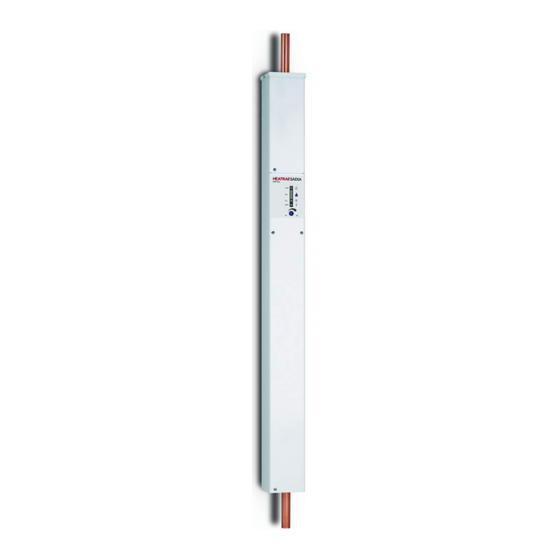
- Page 3 1.0 DESCRIPTION The AMPTEC electric flow boiler is designed to heat re-circulated water used in wet central heating systems. The water is heated when it is passed over electric immersion elements, which are contained in a chamber. The temperature of the water is monitored and controlled by a modulation technique switching on the immersion elements.
-
Page 4: Technical Specification
3.0 TECHNICAL SPECIFICATION Output temperature control range: (C series) C to 80 (U Series) C to 60 Operating voltage 200V - 245V 50Hz Pump supply fuse (internal) T 2A 240V - 20x5mm. ‘RUN’ control input signal requires 200V - 245V 50Hz ‘RUN’... - Page 5 The guarantee will be withdrawn if this product is Not ins talled in accordance with the installation instructio ns 30mm CONTROL ON BOTH SIDES HEATRAESADIA 90mm AMPTEC BOILER C600 GC NO. E B-205-02 OPERATING TEMPERATU RE 65-80C PRESSURE 3 BAR MAX 220-240V ~ 5-6KW...
- Page 6 DO NOT FIT THE AAV DIRECTLY ABOVE THE BOILER. The Amptec boiler is suitable for operation in sealed or open vented systems. It is also suitable for schemes such as heating only, W plan, S plan, zone heating, under floor heating, micro-bore via a manifold, etc. If you are unsure about your application regarding suitability of the boiler please do not hesitate to contact your local supplier or Heatrae Sadia specification team on 01603 420220.
- Page 7 NOTE: TO COMPLY WITH BUILDING REGULATIONS, PART L (PART J IN SCOTLAND), WHEN THE AMPTEC IS USED FOR CENTRAL HEATING PURPOSES, A ROOM THERMOSTAT MUST BE FITTED TO CONTROL THE BOILER (SEE PAGE 15). Do not fit thermostatic radiator valves to the room with the control thermostat, other rooms may be fitted with thermostatic radiator valves.
- Page 8 AS SHOWN WITH 150mm MINIMUM AUTOMATIC AIR VENT DISTANCE FROM BEND. 3. ENSURE NO VALVE IS FITTED BETWEEN THE AMPTEC BOILER & THE EXPANSION KIT/SAFETY DISCHARGE VALVE. PUMP 4. THE BOILER CAN BE ISOLATED BY CLOSING THE PUMP VALVES & THE SERVICE VALVE ON THE RETURN PIPEWORK TO THE BOILER.
- Page 9 AUTOMATIC AIR VENT 150mm 22mm PIPE 28mm PIPE 35mm PIPE FLOW FLOW FLOW PUMP 12 LITRE/ 24 LITRE/ 36 LITRE/ FLOW RELAY SYSTEM 95970136 EXPANSION SAFETY RELIEF SYSTEM SERVICE VALVE 35mm PIPE 28mm PIPE 22mm PIPE FLOW FLOW FLOW DRAIN VALVE 36 LITRE/ 24 LITRE/ 12 LITRE/...
- Page 10 6.0 INSTALLATION - ELECTRICAL REQUIREMENTS ALL WIRING MUST BE CARRIED OUT IN ACCORDANCE WITH CURRENT IEE WIRING REGULATIONS. The AMPTEC boiler must be installed by a qualified competent tradesman in accordance with supplied instructions and drawings to ensure correct operation.
- Page 11 Connections for 2 or more boilers. 1 CONN 5: Main power-supply cables. Connect each boiler to its supply live, neutral, and earth, as described on p.10. The supplies to each boiler can be on different phases if using a 3-phase supply.
- Page 12 OR DOUBLE POLE PROGRAMMER / ETC DEMAND SIGNAL FROM CONTROLS/ PROGRAMMER ETC (SEE TYPICAL WIRING DIAGRAMS) PUMP CONN1 HEAT RESISTANT CABLE CONN5 EARTH BONDING TO BE PERFORMED IN ACCORDANCE AMPTEC BOILER WITH BS7671 FIGURE 8 : BOILER SUPPLY USING EXISTING CONSUMER UNIT...
- Page 13 INCOMING MAINS SUPPLY CABLE INCOMING PROGRAMMER CONTROL CIRCUIT FUSED 3A 0.5mm - 1mm CASE EARTH OUTGOING PUMP SUPPLY CABLE 0.5mm - 1mm SUPPORT BACK OF PCB WHEN TIGHTENING SCREWS ENSURE SCREWS ARE TIGHT. CONN 1 LIVE NEUTRAL EARTH SUPPLY NEUTRAL CONN 5 REMOVE TOP COVER ONLY TO GAIN ACCESS TO THE...
- Page 14 CYLINDER STAT ROOM STAT 2 PORT VALVES C 1 2 2 1 3 BLUE GRN/YLW BROWN GREY ORANGE BLUE GRN/YLW BROWN FROM 3A GREY ORANGE FUSED SPUR OR MCB BOILER TIME CONTROLLER FIGURE 10 : TYPICAL S PLAN WIRING DIAGRAM...
- Page 15 MID POSITION CYLINDER VALVE ROOM STAT STAT 2 1 3 C 1 2 BLUE G/YELLOW BROWN GREY ORANGE FROM 3A FUSED SPUR OR MCB BOILER OPTIONAL CAPACITOR 0.47uF 240v AC TIME CONTROLLER FIGURE 11 : TYPICAL Y PLAN WIRING DIAGRAM PROGRAMMABLE ROOM THERMOSTAT A B C...
- Page 16 7.0 INSTALLATION - REVISED BUILDING REGULATIONS Heating Controls to comply with the revised Building Regulations (Part L For England. Part J for Scotland). New Dwelling 1. The installation must be a fully pumped system. 2. Independent temperature and time controls for both heating and domestic hot water. 3.
- Page 17 8.0 COMMISSIONING The boiler controls are fully automatic, making the operation very simple. Only after the system has been flushed through and then filled with water inhibitor and set to the correct pressure (sealed systems), can the electrical supply be switched on. Check 1.
- Page 18 5. The pump is operated from the boiler control. It should be connected to the pump terminals on the boiler control board. The pump will run whenever the CALL indicator is illuminated (green) either flashing or steady, and it will also continue to run for 1 minute after the demand has ceased. A bypass must be incorporated in systems where the heating load can shut down, i.e.
- Page 19 MAIN POWER ON SHORT/OPEN SHORT/OPEN CIRCUIT AT CONTROL CIRCUIT THERMISTOR OVER TEMPERATURE? ALARM 2 (TEMPERATURE SWITCH) PREVIOUS WATER HEATING LOWER WATER HEATING DEMAND TEMPERATURE > TEMPERATURE TO 80°C DEMAND? 85°C WATER OVER RUN PUMP WATER PRESENT? ALARM 1 TEMPERATURE < (1MINUTE) (WATER CHECK) 10°C...
- Page 20 CALL indicator (green) is illuminated. The gradual build up in heating power of the boiler can be seen on the front panel. AMPTEC The HEAT indicator also shows the boiler modulating when it reaches operating temperature, or if the temperature rise is too quick.
- Page 21 11.0 REPLACING THE MAIN POWER PCB Note. Before any maintenance is carried out on the system, ensure that the electrical supply has been disconnected first. Care must be taken as the water may be scalding hot and at high pressure. Maintenance on the boiler can only be carried out by a qualified and competent tradesman in accordance with supplied instructions.
-
Page 22: Fault Finding
3 port valves. The capacitor required is 0.47 micro-farads suitable for 275 volts AC (X2 style). These capacitors are available from Heatrae Sadia part number 95 612 708. 13.0 ALARM RESET There are 3 steps to reset a tripped condition: - Switch “OFF”... - Page 23 THE BOILER IS NOT GO TO SUPPLY LED OFF THE SUPPLY LED OPERATING FAULT FINDING SECTION ILLUMINATED PLEASE CHECK THE FOLLOWING BEFORE GOING THROUGH THE FAULT FINDING CHART: CHECK INSTALLATION IS IS AN CORRECT GO TO ALARM ALARM LED FAULT FINDING SECTION ILLUMINATED ALL ISOLATING VALVES ARE OPEN...
- Page 24 SUPPLY LED OFF IS THE CHECK 240V IS SUPPLIED MAIN SUPPLY TO THE MAIN POWER TERMINAL AVAILABLE CONN5 IS THERE CHECK FOR SHORT CIRCUITS 230V ON FS1 LINK ON WIRING TO THE PUMP. & NEUTRAL IF OK REPLACE FS2 FUSE. (MAIN TERM) T 2A 240V 20 x 5mm IS THERE...
- Page 25 CALL LED NOT FLASHING IS THE 230V CHECK AND SET THE PROGRAMMER DEMAND AVAILABLE AND THERMOSTATS ON IS THERE 230V CHECK THE WIRING TO BETWEEN R AND N THE BOILER CONTROL IS RIBBON CHECK THE IDC CONNECTOR CABLE CONNECTOR ON THE CONTROL PCB FULLY HOME IS NEUTRAL NEUTRAL MUST BE CONNECTED...
- Page 26 240V 10Amps N/O (Normally Open) Isolation Coil to Contact - 415V minimum working. Capacitor 4.7uF 240V 50Hz Class X2 For 2 boilers use Heatrae Sadia part number 95 970 135 For 3 boilers use Heatrae Sadia part number 95 970 136...
- Page 27 FIGURE 21: AMPTEC DOUBLE BOILER WIRING...
- Page 28 Note, this is only required if there is doubt with regard to supply limitations and an electric shower that heats the water at the same time as the Amptec boiler is used. It is not required with power showers which only pump the water.
-
Page 29: Environmental Information
This Guarantee in no way affects the statutory rights of the consumer. The policy of Heatrae Sadia is one of continuous product development and, as such, we reserve the right to change specifications without notice. 17.0 ENVIRONMENTAL INFORMATION. - Page 30 19.0 TECHNICAL FICHE Product name Amptec Standard Model identifier C400 C600 C900 C1100 C1200 Electric boiler space heater Rated heat output Prated Useful heat output at rated heat output and 10.8 11.9 hign temperature regime (2) Useful heat output at 30% of rated heat...
- Page 31 PRODUCT FICHE - ELECTRIC BOILERS Product name Amptec Standard Model identifier C400 C600 C900 C1100 C1200 Seasonal space heating energy efficiency class Rated heat output Prated Seasonal space heating energy efficiency η s Annual energy consumption Q HE 8661 12986...
- Page 32 Parts Center OUR NATIONWIDE NETWORK OF CUSTOMER SUPPORT ENGINEERS Tel: 0344 292 7057 Heatrae Sadia has its very own dedicated nationwide network of highly trained www.partscenter.co.uk customer support engineers so you can have peace of mind that we’re always here to help.
Need help?
Do you have a question about the Amptec and is the answer not in the manual?
Questions and answers