Table of Contents
Advertisement
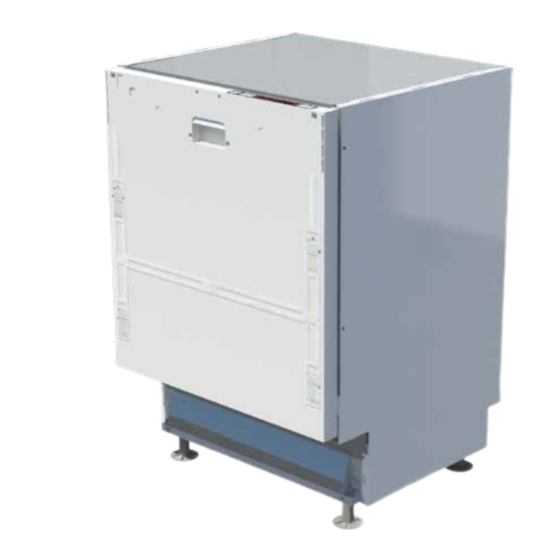
Dishwasher
Installation Instructions
(To be used in conjunction with User Instructions)
Throughout this manual the
following symbols are used.
Warning for hazardous
situations with regard
to life and property.
Warning for
electric shock.
LAM8605
Advertisement
Table of Contents

Related Manuals for Lamona LAM8605


Summary of Contents for Lamona LAM8605
-
Page 1: Installation Instructions
LAM8605 Dishwasher Installation Instructions (To be used in conjunction with User Instructions) Throughout this manual the following symbols are used. Warning for hazardous situations with regard to life and property. Warning for electric shock. - Page 2 Introduction • Please read the Installation Instructions to ensure safe fitting and use of the appliance. • The dishwasher should be fitted by a suitably competent and qualified person. • Please keep these instructions in a safe place for future reference. Safety Information Two person lift.
-
Page 3: Tools Required
Installation Tools required 24mm open DO NOT use high ended spanner speed impact power tools. Sealant T20, flat and cross head screw drivers Parts supplied +50mm A (3.5x14) B (4x43mm) C (4x36mm) www.howdens.com Copyright © 2016 Howden Joinery Ltd. All rights reserved. - Page 4 1 - Dimensions Position the dishwasher relative to service connections. 820-920mm 550mm 598mm 570mm 818mm (+100) 600mm 160mm 100mm (+100) 44mm 100mm 15mm 2 - Opening height Opening height from the floor to the underside of the worktop is between 820mm - 920mm. *HJ Kitchen Installation Manual (*nominal 890mm) For standard installation...
- Page 5 3 - Height adjustment Final height adjustment may be required after positioning of the dishwasher. Front feet Rear feet Flat head DO NOT use high speed screw driver impact power tools. DO NOT damage the plastic screw heads. 4a - Décor door - ‘H’ frame set-up 267mm Centre line www.howdens.com...
- Page 6 4b - Décor door Unscrew the two screws and remove the plastic ‘H’ bracket. Retain the screws for stage 4c. Cross head A (3.5x14) x2 4c - Décor door Secure with the screws retained from stage 4b plus two additional screws from the accessory bag. A (3.5x14) x4 Fit handles at this stage, if required, (screws may need countersinking).
- Page 7 4d - Décor door Remove the existing fixings and using the 43mm screws supplied, secure at positions 2 and 5. Ensure correct alignment with the top of the door, (2mm overlap at top). B (4x43mm) x4 DO NOT fully tighten the screws at this stage.
- Page 8 5a - Décor drawers frontal - ‘H’ frame set-up Unscrew the two screws and remove the plastic ‘H’ bracket. Retain the screws for stage 5b. Cross head 130mm A (3.5x14) x2 267mm 60mm 130mm 2 x 356mm drawer fronts = 712mm Centre Normal door height = 716mm Therefore space between drawer fronts = 3-4mm...
- Page 9 5c - Décor drawers frontal Remove centre rail. 5d - Décor drawers frontal Remove the existing fixings and using the 43mm screws supplied, secure at positions 2, 3 and 5. Ensure correct alignment with the top of the door, (2mm overlap at top). B (4x43mm) x6 DO NOT fully tighten the screws at this stage.
- Page 10 5e - Décor drawers frontal If necessary make final alignment and fully tighten the screws. Make sure screws are fastened flush but do not over- tighten. 6 - Worktop protection strip NOTE: This strip must be fitted to avoid damage to the worktop. Ensure a clean and Ensure tape is set to edge of square edged dust free surface.
- Page 11 7 - Locate securing brackets Fold and insert brackets according to worktop material. 8 - Positioning appliance NOTE: If necessary loosen and rotate the water hose towards the water supply and re-tighten. Always use the new NOTE: Ensure hoses are not kinked or trapped hose supplied with the behind the dishwasher.
- Page 12 9 - Securing appliance Adjust height so that the dishwasher touches the underside of the worktop by adjusting front and rear feet. Then secure using screws provided, (side fixing for solid worktops and top fixing for wooden worktops). Solid worktop Timber worktop A (3.5x14) x4 A (3.5x14) x4...
- Page 13 10 - Connecting appliance 1000mm 500mm 300mm All dimensions are to the floor. 1000mm max. 100mm 500mm 300mm DO NOT insert the hose too deep into the waste pipe. Maximum hose length, 4 metres. www.howdens.com...
- Page 14 NOTE: Ensure hoses are not kinked or trapped NOTE: If necessary loosen and rotate the water hose behind the dishwasher. towards the water supply and re-tighten. Always use the new hose supplied with the dishwasher. REMOVE CAP Ensure cap / top is removed from waste pipe. Ensure water is turned on and the isolator valve is accessible after fitting.
- Page 15 Incorrect waste pipe configuration. Correct waste pipe configuration. After connecting and running a test program check all connections for leaks. 11 - Trim plinth to suit Once décor door / drawer frontals are fitted correctly, trim plinth to suit. Apply sealant www.howdens.com...
- Page 16 MAKING SPACE MORE VALUABLE Product information correct at the time of publication in July 2016. The company has a policy of continuous product development and reserves the right to change any products and specifications given in this manual. Subject to the Terms and Conditions of Trading, a copy of the Howdens Joinery Terms and Conditions is available upon request.
Need help?
Do you have a question about the LAM8605 and is the answer not in the manual?
Questions and answers