Table of Contents
Advertisement
Advertisement
Table of Contents

Related Manuals for CommScope ION-U L 7/8/85/17/19


Summary of Contents for CommScope ION-U L 7/8/85/17/19
- Page 1 ION™-U Optical Remote Unit ION-U L 7/8/85/17/19 User's Manual MF0147A0A...
- Page 2 DISCLAIMER: This document has been developed by CommScope, and is intended for the use of its customers and customer support personnel. The information in this document is subject to change without notice. While every effort has been made to eliminate errors, CommScope disclaims liability for any difficulties arising from the interpretation of the information contained herein.
-
Page 3: Table Of Contents
HEALTH AND SAFETY WARNINGS ABOUT COMMSCOPE 1.3. INTERNATIONAL CONTACT ADDRESSES FOR CUSTOMER SUPPORT INTRODUCTION 1.4. PURPOSE 1.5. THE ION-U L 7/8/85/17/19 REMOTE UNIT 2. FUNCTIONAL DESCRIPTION 2.1. SISO AND MIMO OPERATION 2.2. ION-U 7/8/85/17/19 PORTS 3. COMMISSIONING 3.1. MECHANICAL INSTALLATION 3.1.1. - Page 4 Table of contents 4.3. STATUS LED ALARMS 4.4. EXTERNAL ALARM INPUTS 4.5. TROUBLESHOOTING 5. MAINTENANCE 5.1. GENERAL 5.2. RU POWER SUPPLY REPLACEMENT 6. APPENDIX 6.1. ILLUSTRATIONS 6.2. ELECTRICAL SPECIFICATIONS 6.3. ENVIRONMENTAL AND SAFETY SPECIFICATIONS 6.4. MECHANICAL SPECIFICATIONS 6.5. SPARE PARTS 7.
- Page 5 4-5 Attach M6 nut to threaded pins ..............23 figure 4-6 Completed SISO RU Mount ..............23 figure 4-9 ION-U L 7/8/85/17/19 Connectors ............26 figure 4-10 Grounding bolt ..................28 figure 4-11 Grounding bolt, schematic view .............. 28 figure 4-12 AC power cable ..................
- Page 6 1-1 List of international contact addresses ............14 table 4-1 Specified torques ..................20 table 4-2: ION-U L 7/8/85/17/19 Connectors ............27 table 4-3 AC power cable ..................29 table 4-4 DC power cable ..................29 table 4-5 Vdc/100 power cable .................
-
Page 7: General
1 General 1. General 1.1. Used Abbreviations 3GPP Generation Partnership Project AC/DC Alternating current / Direct Current AIMOS Andrew Integrated Management and Operating System Automatic Level Control BITE Built-In Test Equipment Base Transceiver Station "Conformité Européenne" ("European Conformity") Compact Disk Channel Power Detection Downlink Declaration of Conformity... -
Page 8: Health And Safety Warnings
1 General 1.2. Health and Safety Warnings 1. Danger: Obey all general and regional installation and safety regulations relating to work on high voltage installations, as well as regulations covering correct use of tools and personal protective equipment. 2. Danger: Laser radiation! Do not stare into the beam; do not view it directly or with optical instruments. - Page 9 1 General PD (mW/cm²) is the allowed Power Density limit acc. to 47 CFR 1.1310 (B) for general population / uncontrolled exposures which is F (MHz) / 1500 for frequencies from 300MHz to 1500MHz 1 for frequencies from 1500MHz to 100.000MHz RF exposure compliance may need to be addressed at the time of licensing, as required by the responsible FCC Bureau(s), including antenna co-location requirements of 1.1307(b)(3).
- Page 10 1 General Equipment Symbols Used Please observe the meanings of the following symbols used in our equipment: Symbol Compliance Meaning Alert sign to R&TTE Indicates conformity with the R&TTE Symbol directive 1999/5/EC certified by the notified body no. 0700. User’s Manual for ION-U 7/8/85/17/19 Page 10...
-
Page 11: About Commscope
* In case the Declaration of Conformity (DoC) for the product was not included in the manual CD delivered, it is available upon request from the local sales offices or directly from CommScope at one of the addresses listed in the following chapter. -
Page 12: International Contact Addresses For Customer Support
1 General 1.3. International Contact Addresses for Customer Support Americas: Canada United States CommScope Canada Andrew LLC, A CommScope Company 505 Consumers Road, Suite 803 620 North Greenfield Parkway Mail Toronto M2J 4V8 Mail Garner, NC 27529 Canada U.S.A. +1-905-878-3457 (Office) - Page 13 E-mail wisupport.ch@commscope.com Italy Iberia Region - Spain & Portugal Andrew España S.A. CommScope Italy S.r.l., Faenza, Italy A CommScope Company Avda. de Europa, 4 - 2ª pta. Via Mengolina, 20 Parque Empresarial de la Moraleja Mail 48018 Faenza (RA)
- Page 14 1 General Czech Republic CommScope Solutions Czech Republic C-Com, spol. s r.o U Moruší 888 Mail 53006 Pardubice Czech Republic +49 871 9659171 (Office) Phone +49 171 4001166 (Mobile) +49 871 9659172 E-mail wisupport@commscope.com Africa & Middle East: Middle East & North Africa South Africa CommScope Solutions International Inc.
-
Page 15: Introduction
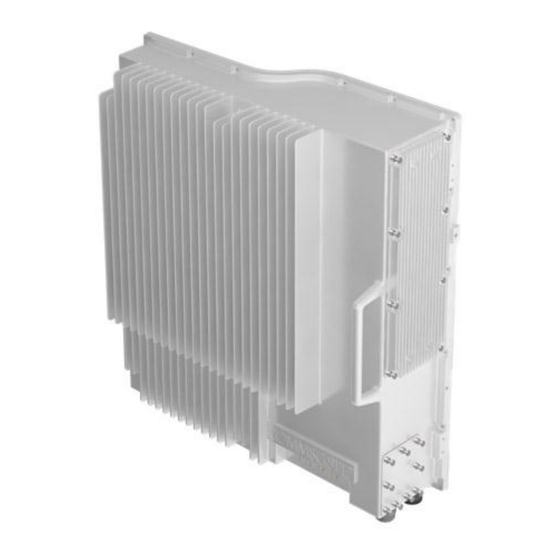
RF signals are transported to the remote units via optical fibers. 1.5. The ION-U L 7/8/85/17/19 Remote Unit The ION-U 7/8/85/17/19 is a low power remote unit for Cell700, LMR800, Cell850, AWS, and Extended PCS1900 Band Applications. The unit is compatible with analog, GSM, EDGE, IS-95, CDMA2000, EVDO, W-CDMA, HSDPA, and LTE modulation standards. - Page 16 0 Introduction The ION-U L 7/8/85/17/19 is capable of supporting both SISO and MIMO. RF signals are transported to the remote units via single mode fiber at 1310 nm. MIMO is achieved with the use of 4 fibers and the pairing of two interlinking RUs.
-
Page 17: Functional Description
2 Functional Description 2. Functional Description In the Downlink (DL) path, the remote unit provides: Optical to RF conversion of the input optical signal Automatic Gain Control (AGC) of each converted signal to compensate for optical losses RF amplification of the converted RF signal for transmission while maintaining a good signal-to-noise ratio ... -
Page 18: Ion-U 7/8/85/17/19 Ports
Expansion Ports The Expansion UL and Expansion DL ports are QMA female connectors that are used to connect to a CommScope expansion unit to provide additional bands. User’s Manual for ION-U 7/8/85/17/19 Page 18... - Page 19 2 Functional Description Optical Ports The LC-APC optical connectors are used to send and receive the signals between the RU and the Master Unit’s OTRx modules. The DL optical port receives downlink signals from the MU OTRx. The UL optical port transmits uplink signals to the MU OTRx.
-
Page 20: Commissioning
3 Commissioning 3. Commissioning 3.1. Mechanical Installation 3.1.1. General Read the health and safety warnings in chapter 1.2. 1. Warning: Do not install the unit in a way or at a place where the specifications outlined in the Environmental and Safety Specifications leaflet of the supplier are not met. -
Page 21: Wall-Mounting Procedure
3 Commissioning 3.1.2. Wall-Mounting Procedure 1. Check the suitability of the wall-mounting kit and the wall. 2. Install wall-mounting bracket using 4 M6 screw anchors (not included*) according to the drilling layout. Confirm that the bracket is securely fastened to the wall. The M6 screw anchors are not included as part of the RU delivery because the suitable... - Page 22 3 Commissioning 4. Install the Remote Unit on the wall-mounting bracket lifting the RU into place and lowering it down onto the bracket. The M6 pins must align with the slots in the bracket to support the RU. B0303A8A figure 3-3 RU placed on wall mounting bracket 5.
- Page 23 3 Commissioning 6. Fasten the Remote Unit to the bracket using a washer and M6 nut. Slide the washer over the threaded pins that were installed in step 3 and then screw the nut onto the pins (on both sides) and tighten securely.
-
Page 24: Electrical Installation
For example, use torque wrench of item no. 244379 available from the CommScope e-catalog. Do NOT use your hands or any other tool (e.g. a pair of pliers)! This might cause damage to the connector and lead to a malfunction of the Remote Unit. - Page 25 3 Commissioning 11. Caution: For unstabilized electric networks, which frequently generate spikes, the use of a voltage limiting device is advised. 12. Caution: The unit complies with the surge requirement according to EN 61000-4- 5 (fine protection); however, installation of an additional medium (via local supply connection) and/or coarse protection (external surge protection) is recommended depending on the individual application in order to avoid damage caused by overcurrent.
-
Page 26: Connections
3 Commissioning 3.2.2. Connections The ION-U RU ports and connectors shown below are located at the base of the RU. figure 3-7 ION-U L 7/8/85/17/19 Connectors ION-U L 7/8/85/17/19 Connectors/Indicators Port/Conn Purpose Type LOCAL DB-9 Female This connector is used for external modem... - Page 27 M8 bolt, hex ground cable to the RU nut, & washers ANT RF This connector is used for transmitting and N-type female receiving signals to and from an antenna or antenna splitter. table 3-2: ION-U L 7/8/85/17/19 Connectors MF0147A0A Page 27...
-
Page 28: Grounding (Earthing)
3 Commissioning 3.2.3. Grounding (Earthing) The RU must be grounded (earthed). Connect an earth-bonding cable to the grounding bolt connection provided on the outside of the remote unit (near the Mains connector) as shown in figure 3-8. Do not use the grounding connection to connect external devices. figure 3-8 Grounding bolt figure 3-9 Grounding bolt, schematic view 2. -
Page 29: Mains Power Connection
3 Commissioning 3.2.4. Mains Power Connection Before connecting electrical power to the units, the system must be grounded (earthed) as described in the previous chapter. The Mains power must be connected to the Mains connector of the unit for operation of the RU. - Page 30 3 Commissioning The Vdc/100 power cable is available for locations where the power drawn on each cable must be limited to a maximum of 100 VA. This cable is a 3.2 m (10.5 ft) 16 AWG cable with a 7-pin Amphenol C016 series plug on one end to connect to the RU Mains connector.
-
Page 31: Antenna Connection
3 Commissioning 3. The Mains cable must be properly secured observing local regulations and electrical codes. Be sure to allow enough slack in the cable at the RU to plug or unplug the cable into the Mains connector of the RU. 4. -
Page 32: Expansion Ports Connections
(2 N-m / 20 in lb), with 13/16 in opening to tighten the N-type antenna connectors. For example, use torque wrench of item no. 244379 available from the CommScope e-catalog. Do NOT use your hands or any other tool (e.g. a pair of pliers)! This might cause damage to the connector and lead to a malfunction of the Remote Unit. -
Page 33: Alarm Port
3 Commissioning 1. Connect an RF cable with QMA male connectors between the UL Expansion port connector of the RU to the UL port of the expansion unit. Press the QMA connector of the cable onto the UL port of the RU until it clicks into place to connect the cable. -
Page 34: Control Connector Rs-232 - Local Interface
3 Commissioning 7-Pin Binder 712 Series Assignment +V_FAN Fan1 Alarm In Fan1 (PWM) Out GND_FAN Fan2 Alarm In B303AMA Fan2 (PWM) Out table 3-7 Pwr/Ctrl figure 3-17 Pwr/Ctrl Connector Connector 3.2.9. Control Connector RS-232 - Local Interface This DB-9 female connector is used for external modem communication with a possible extension unit and for local connection with a laptop. -
Page 35: Optical-Fiber-Cable Connection - Rules
3 Commissioning 3.3. Optical-Fiber-Cable Connection - Rules Main optical system parameters: Fiber: Single mode fiber, type is 9.5/125 µm Fiber-cable connectors LC/APC ION-U system: The pigtails for the connection between Master Unit and Remote Unit must have a sufficient length. Protection for the optical fibers must be provided where the fibers feed into the units. - Page 36 3 Commissioning Connect the fiber-optic cables by inserting the cable end into the laser receptacle. Do not use any index-matching gels or fluids of any kind in these connectors. Gels are intended for laboratory use and attract dirt in the field. ...
-
Page 37: Optical Cable Installation
3 Commissioning 3.3.1. Optical cable installation 1. Locate the Optics connector cover on the lower right side of the RU. Loosen the four cover screws, remove the cover, and set it aside. Removing this cover allows access to the UP and DL optical connectors. Optical Connectors Cover... - Page 38 3 Commissioning Sealing figure 3-22 Insert fiber optic cables through sealing nut 5. Then insert the optical cables through the opening in the cable gland clamp ring 6. Connect the optical cables to the proper UL and DL LC/APC connectors. Connect LC/APC Optical Cables...
-
Page 39: Commissioning
3 Commissioning 8. Press the split-seal up into the clamp ring opening. Split-seal Sealing figure 3-25 Press split-seal into opening 9. Tighten the sealing nut securely. Sealing figure 3-26 Tighten sealing nut 10. Replace the optics metal cover and tighten the four screws that were loosened in step 1. -
Page 40: Alarms
4 Alarms 4. Alarms 4.1. Bite and Alarms The Built-In Test concept comprises the monitoring of the power supplies, the power amplifiers, and the optical interface. All alarms that occur can be checked via software at the master unit. 4.2. Handling of Alarms As soon as the software acknowledges a valid alarm, a message is transmitted to the master unit. -
Page 41: Status Led Alarms
4 Alarms 4.3. Status LED Alarms For local supervision, a status LED on the connector panel of the remote unit adjacent to the Expansion ports provides a visual warning of an alarm condition. The color of the LED indicates the severity of the alarm. Detailed alarm information is available through the ION-U software interface. -
Page 42: External Alarm Inputs
Subminiature circular connectors series 712 with five contacts, which are contained in the alarm kit, can be ordered directly from the Binder Connector Group, the manufacturer, or indirectly from CommScope. For the designation of the alarm kit see chapter 6.5 Spare Parts. -
Page 43: Troubleshooting
4 Alarms 4.5. Troubleshooting The status of the remote unit can be checked via the master unit (for details please refer to the ION-U software manual). Locally, the status can be checked at the LED, see chapter 4.3 Status LED Alarms. MF0147A0A Page 43... -
Page 44: Maintenance
The remote unit does not require preventative maintenance measures. Maintenance of the ION-U L 7/8/85/17/19 should be performed by replacing only components that are described in this chapter. In order to maintain the warranty, avoid unintentional damage to the seals on the modules. -
Page 45: Ru Power Supply Replacement
5 Maintenance 5.2. RU Power Supply Replacement The power supply for the RU is a field replaceable module. The type of power supply used by the RU (AC, DC, or Vdc/100) is dependent on the model number of the RU. Before starting any maintenance on the RU, read the health and safety warnings in chapter 1.2 and the electrical installation general information in chapter 4.2.1. - Page 46 5 Maintenance 4. Use a #2 Phillips head or slotted screwdriver to loosen Loosen 8 universal the 8 universal slot/Phillips slot/Phillips screws captive power supply screws carefully remove supply. The weight of the Mains power supply must connector supported as you loosen the figure 5-3 8 RU power supply screws screws to prevent damage to the supply.
- Page 47 5 Maintenance 8. Locate the output connector for the power supply on the left side of the supply. 9. Loosen the 2 Phillips head screws and remove the output connector. figure 5-6 RU power supply output cable 10. Remove the defective supply. figure 5-7 Ru with power supply removed 11.
- Page 48 5 Maintenance 13. Insert the power supply into the RU carefully to avoid damaging any cables. The supply must be supported until the 8 universal slot/Phillips captive power supply screws have been tightened. 14. Tighten universal slot/Phillips captive power supply screws. figure 5-9 Ru insert power supply 15.
-
Page 49: Appendix
6 Appendix 6. Appendix 6.1. Illustrations Need drawings with dimensions here figure 6-1 Installation drawing MF0147A0A Page 49... -
Page 50: Electrical Specifications
6 Appendix 6.2. Electrical Specifications Please refer to the “ION-U_LP_RU_US_PA-106156-EN.GB.pdf” data sheet for the Remote Unit’s electrical specifications. 6.3. Environmental and Safety Specifications Please refer to the “ION-U_LP_RU_US_PA-106156-EN.GB.pdf” data sheet for the Remote Unit’s environmental and safety specifications. 6.4. Mechanical Specifications Please refer to the “ION-U_LP_RU_US_PA-106156-EN.GB.pdf”... -
Page 51: Spare Parts
If a FRU which is not included in the following list needs to be replaced, please contact customer service for additional instructions. ION-U L 7/8/85/17/19 Spare Parts List Designation: ID No: Need Spare Parts... -
Page 52: Index
MIMO applications ..........18 Mounting Wall ..............22 CE Declaration of Conformity (DoC) ..... 11 Commissioning General ............40 CommScope ............11 Optical cable installation ........38 Connection Rules Optical Ports ............20 Optical-Fiber Cables ........36 OPTICS UL ............28 Connections Antenna .............
Need help?
Do you have a question about the ION-U L 7/8/85/17/19 and is the answer not in the manual?
Questions and answers