
Related Manuals for Eaton Form 4D Recloser Control


Summary of Contents for Eaton Form 4D Recloser Control
- Page 1 COOPER POWER Reclosers SERIES Effective April 2018 MN280091EN New Issue Form 4D Recloser Control Communications Module; Installation Instructions...
-
Page 2: Disclaimer Of Warranties And Limitation Of Liability
CONTENTS OF THIS DOCUMENT SHALL NOT BECOME PART OF OR MODIFY ANY CONTRACT BETWEEN THE PARTIES. In no event will Eaton be responsible to the purchaser or user in contract, in tort (including negligence), strict liability or other-wise for any special, indirect, incidental or consequential damage or loss whatsoever, including but not limited to... -
Page 3: Table Of Contents
Contents DISCLAIMER OF WARRANTIES AND LIMITATION OF LIABILITY . . . . . . . . . . . . . . . . . . . . . . . . . . . . . . . . . . . . I SAFETY INFORMATION . -
Page 4: Safety Information
FOR LIFE FOR LIFE Eaton meets or exceeds all applicable industry standards relating to product safety in its Cooper Power™ series products. We actively promote safe practices in the use and maintenance of our products through our service literature, instructional training programs, and the continuous efforts of all Eaton employees involved in product design, manufacture, marketing, and service. -
Page 5: Product Information
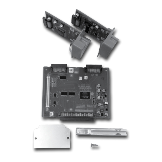
Form 4D Recloser Control Communications Module Product information Table 1 . Kit part identification Item Description Communications Module 1 or 2 Introduction Communications Base Service Information MN280091EN provides installation and Circuit Board operation instructions for the Form 4D recloser control. Support Bar, Aluminum... - Page 6 Form 4D Recloser Control Communications Module otee: Rest the lower portion of the module on the swing panel opening. Three (3) Retaining Bar Nuts Module Swing Panel Ground Link Nut Figure 1 . Loosen retaining bar nuts and tilt module back Figure 3 .
- Page 7 Form 4D Recloser Control Communications Module Install the communications base board partially into the slots. Make sure the connections for the communications modules are facing toward the front of the control and to the outside. See Figure 5. Figure 7 . Hole in the base circuit board 11.
- Page 8 Form 4D Recloser Control Communications Module 13. Install the communications module into the top communications module slot (Com Port 1) and secure with two of the #6-32 screws supplied with the kit. See Figure 11 and Figure 12. Figure 9 . Pushing the base circuit board into the guide grooves 12.
-
Page 9: Install Module
Form 4D Recloser Control Communications Module Install module 14. A second communications module can be installed in the lower slot (Com Port 2) (Figure 13) or the supplied CAUTION cover can be placed over the slot if it is not needed (Figure 14). - Page 10 Form 4D Recloser Control Communications Module This page is intentionally left blank. INSTALLATION INSTRUCTIONS MN280091EN April 2018...
- Page 11 Form 4D Recloser Control Communications Module This page is intentionally left blank. INSTALLATION INSTRUCTIONS MN280091EN April 2018...
- Page 12 Waukesha, WI 53188 United States Eaton.com/cooperpowerseries © 2018 Eaton All Rights Reserved Printed in USA Eaton is a registered trademark. For Eaton's Cooper Power series product Publication No. MN280091EN information April 2018 call 1-877-277-4636 or visit: All trademarks are property www.eaton.com/cooperpowerseries.
Need help?
Do you have a question about the Form 4D Recloser Control and is the answer not in the manual?
Questions and answers