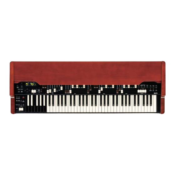
Hammond XK-5 Service Manual
Hide thumbs
Also See for XK-5:
- Owner's playing manual (174 pages) ,
- Owner's manual (170 pages) ,
- Quick start manual (42 pages)

Related Manuals for Hammond XK-5


Summary of Contents for Hammond XK-5
-
Page 1: Service Manual
SERVICE MANUAL CAUTION ! see safety notice inside MAR.2017 SUZUKI MUSICAL INST.MFG.CO.,LTD. 2-25-12, RYOKE, NAKAKU, HAMAMATSU, 430-0852 JAPAN... - Page 2 SAFETY NOTICE Great care has been taken in the design and manufacture of this product to assure that no shock hazard exists on any exposed metal parts. Internal service operations can expose the technician to hazardous line voltages and accidentally cause these voltages to appear on exposed metal parts during repair or reassembly of product components.
-
Page 3: Table Of Contents
XK-5 -Table of Contents- 1.SPECIFICATIONS 2.BLOCK DIAGRAM 3-1~3-8 3.TEST AND ADJUSTMENT 4.WIRING CONNECTION 5-1 ~ 5-3 5.WIRING CHART 6.PRINTED WIRING BOARD ASS'Y LIST 7.SCHEMATICS 7-1 ~ 7-16 MGH-106A 1/16~16/16 7-17 ~ 7-23 MXH-40A 1/7~7/7 7-24, 7-25 SWH-536A 1/2,2/2 7-26 SWH-537A... - Page 4 XK-5 1.SPECIFICATIONS Controllers Controllers Sound Generator Volume MTW I (Modelled Tone Wheel I) Master Volume 61 polyphony (for manual) Switch 3 polyphony (for pedal) Power On / Off Keyboards Storage 73 (61+12 Preset Keys) USB Flash Drive Water Fall type...
-
Page 5: Peripheral Mxh-40A
XK-5 WR-HZ185-L WR-HZ185-K WR-HZ185-L WR-HZ185-K +3.3V WR-DB602C-A J414 OLED Unit 20x2 J401 J407 J404 VOLUME PED AL SW&LED UPPER DRAWBARS UPPER DRAWBARS D R AW LOWER DRAWBARS LOWER DRAWBARS +3.3V BAR S VOLUME VRH-50A VRH-50A SWH-536A VRH-50B D B-602C VRH-50B RESET SW&LED... - Page 6 3. TEST AND ADJUSTMENT 1 Operation and display check ✞ ☎ ✞ ☎ ✞ ☎ ✝ ✆ ✝ ✆ ✝ ✆ 1. Power on with pressing OVERDRIVE REVERB buttons at the same time. Keep pressing them until the following screen appears. 2.
- Page 7 • Preset key: The corresponding LED is lighted. 3. After checking all of above, turn off the power. *The state of the preset key will not be stored. 2 standard value list Refer to the next page.
- Page 8 2. STANDARD VALUE LIST SETTING SETTING SETTING SETTING STEP SUBJECT SUBJECT SUBJECT SUBJECT PLAY KEYS PLAY KEYS PLAY KEYS PLAY KEYS TEST POINT TEST POINT TEST POINT TEST POINT SPECIFICATION SPECIFICATION SPECIFICATION SPECIFICATION ADJUSTMENT POINT ADJUSTMENT POINT ADJUSTMENT POINT ADJUSTMENT POINT NOTE NOTE NOTE...
- Page 9 3 Adjustment method of the vacuum tube It is required bias and level adjustment when the vacuum tube is exchanged. The parameters of the vacuum tube level adjustment is stored in MGH-106A, so when MXH- 40A, which is already adjusted the bias, is exchanged, MGH-106A is required to adjust the level as MGH-106A is set accordance with MXH-40A.
- Page 10 3.2 Bias adjustment Adjust for trimmer potentiometers of MXH-40A 3.2.1 Preparations 1. Remove the expression pedal or set expression value to the maximum. 2. Turn off OVERDRIVE, EFFECT and UPPER VIBRATO. 3. To enable adjusting VR1,4,5 of MXH-40A by screw driver. 4.
- Page 11 3.2.2 Adjustment and measurement point 3.2.3 Notes for operation of trimmer potentiometers • Use flathead screwdriver which is fit to the hole shown in the figure. (If Philips screwdriver is used, there is in danger of crushing the screw thread) •...
- Page 12 3.2.5 V2 12AX7(If you have an oscilloscope) Set LEVEL around 20 on TUBE CALB2 screen. 1. Set the SEL item to T1X. 2. Observe the vacuum tube side of C176 (T1X out) with the oscilloscope and adjust VR4 to make the upper and lower part of the waveform saturated uniformly. ⇐⇒...
- Page 13 3.3 Level adjustment Adjust the software parameter. The measured adjusted value is stored to the memory of MGH- 106A. 3.3.1 Environment measurement For measuring the output of LINE OUT L, prepare one of the following environments. • The mixer with level meter •...
-
Page 14: Panel Sw - L Swh-536A
5.WIRING CHART XK-5 MAIN PLUG FROM TO PLUG WIRE TO PWB FUNCTION MGH-106A No. PIN No. & PIN No. COLOR NAME J303-3 WHT J401 MXH-40A SPI_SCK PLUG FROM TO PLUG WIRE TO PWB FUNCTION -4 WHT No. PIN No. & PIN No. COLOR... -
Page 15: Endblock L Sw Swh-537A
XK-5 ENDBLOCK L SW PLUG FROM TO PLUG WIRE TO PWB FUNCTION SWH-537A No. PIN No. & PIN No. COLOR NAME 11 J304-11 WHT J501 MXH-40A PLUG FROM TO PLUG WIRE TO PWB CU-1 RING FUNCTION 12 J304-12 BLK MXH-40A DGND No. - Page 16 XK-5 DRAWBAR (MANUAL-LOWER-R) VRH-50B PLUG FROM TO PLUG WIRE TO PWB FUNCTION No. PIN No. & PIN No. COLOR NAME J414-4 WHT J902 SWH-538A -5 WHT 1 3/5' -6 WHT -7 WHT -8 WHT 1 1/3' -9 WHT 2 2/3'...
- Page 17 6.PRINTED WIRING BOARD ASS'Y LIST XK-5 FUNCTION PWB.NAME PART No. MAIN MGH-106A 00228-26241 PERIPHERAL MXH-40A 00230-07231 PANEL SW - L SWH-536A 00225-45276 ENDBLOCK L SW SWH-537A 00225-45286 PANEL SW - R SWH-538A 00225-45301 JACK CNH-44A 00225-45266 PRESET KEY CONTACT KCH-21A...
- Page 18 XK-5 NU : NotUsed JPS : Connected with pattern VDDCORE VDD_ARM_CAP GND_1 i.MX6Q - POWER 2 NVCC_3V3 GND_2 VDDARM_IN_1 i.MX6Q - POWER 1 VDDARM_CAP_1 GND_3 NVCC_LCD VDDARM_IN_2 VDDARM_CAP_2 C511 C512 C513 C521 C522 C523 C524 GND_4 VDDARM_IN_3 VDDARM_CAP_3 AA10 0.22uF 0.22uF...
- Page 19 XK-5 ETH_3V3 Power Group NVCC_CSI:1.8V i.MX6Q - EIM i.MX6Q - DISP;CSI Audio Master Clock EIM_LBA EIM_LBA i.MX6Q R263 DISP0_CLK RESET_KEY EIM_OE EIM_OE (CSI0_HSYNCH) AUD_MCLK CSI0_MCLK DI0_DISP_CLK CSPI5_MOSI SD1_CMD ENET_MDC RESET_KEY RESET_SWLED EIM_RW EIM_RW (CSI0_PIXCLK) DSP_BOOTCOMPLETE CSI0_PIXCLK CSPI5_CLK SD1_CLK ENET_MDIO RESET_SWLED...
- Page 20 XK-5 DRAM_D[63..0] DRAM_A[15..0] DRAM_D0 i.MX6Q - DDR AC14 DRAM_A0 DRAM_D0 DRAM_A0 DDR_1V5 DDR_1V5 DRAM_D1 AB14 DRAM_A1 DRAM_D1 DRAM_A1 DRAM_D2 AA14 DRAM_A2 DRAM_D2 DRAM_A2 DRAM_D3 DRAM_A3 DRAM_SDCLK0 DRAM_D3 DRAM_A3 DRAM_D4 DRAM_A4 DRAM_D4 DRAM_A4 DRAM_D5 AE13 DRAM_A5 DRAM_D5 DRAM_A5 DRAM_A0 DRAM_A0 DRAM_D6...
- Page 21 XK-5 NotUsed GEN_3V3 C197 0.1uF BOOT_COMPLETE R107 SPINOR_MOSI SPINOR_MISO 4700 GEN_3V3 SPINOR_CLK R424 HOLD SPINOR_CS0 NC7SP125P5X N25Q256A13ESF40 C206 0.1uF FRAM 1Mbit EIM_DA0 EIM_D24 EIM_DA1 EIM_D25 EIM_DA2 EIM_D26 EIM_DA3 EIM_D27 EIM_DA4 EIM_D28 EIM_DA5 EIM_D29 EIM_DA6 EIM_D30 EIM_DA7 EIM_D31 EIM_DA8 EIM_DA9 EIM_CS0...
- Page 22 XK-5 FB29 PMIC_5V BLM21PG221SN1D(220ohm 2A) C208 miniSMDC050F C209 150uF NU : NotUsed VBus GEN_3V3 USB A-TYPE FRAME R109 R110 USB_HOST_DN UBA-4R-S14HD-4S SD3_WP FL_GND SD3_DATA2 USB_HOST_DP DET1 SD3_DATA3 SD3_CD_B GEN_3V3 DLW21SN900SQ2L(90ohm 330mA) SD3_CMD CHIP COMMON MODE COIL GND1 SD3_CLK C210 C211...
- Page 23 XK-5 NFM31KC104R1H3(0.1uF 6A) BM03B-XAFF-TF CODEC_RX 100p 100p CODEC_TX CODEC_RXCLK 100p OPEN 100p CODEC_TXCLK JP11 Solder Jumper NU : NotUsed CODEC_FSR 100p 100p JPS : Connected with pattern GEN_3V3 CODEC_FST C498 FB34 100p 1000uF C499 FAST FB35 100p 6.3V SLOW CODEC_MCK...
- Page 24 XK-5 AUX_3V15 U12B GEN_3V3 VGEN1_1V5 SYS_4V2 VIN1 VGEN1 GEN_3V3 VGEN2_1V5 C218 C212 C213 C214 C215 C216 C217 VIN2 VGEN2 C219 0.47uF SYS_4V2 VGEN3_2V5 0.1uF 0.1uF 0.1uF 0.1uF 0.1uF 0.1uF 4.7uF C220 VIN3 VGEN3 C221 0.47uF VGEN4_1V8 4.7uF C222 VGEN4 C223 0.47uF...
- Page 25 XK-5 NU : NotUsed JPS : Connected with pattern GEN_3V3 A6H-8101 POWER R432 R433 R434 R435 R436 R437 R438 R439 R131 R132 R133 R134 R135 R136 R137 R138 R139 R140 R141 R142 R143 R144 R145 R146 R147 R148 R149 R150...
- Page 26 XK-5 SRIO NU : NotUsed U15P mount&value change BOOT STRAP CONFIGURATION RIORXP0 RIOTXP0 RIORXN0 RIOTXN0 VCC1V8_AUX VCC1V8_AUX RIORXP1 RIOTXP1 GPIO RIORXN1 RIOTXN1 R211 BM_GPIO_00 R212 1000 BM_GPIO_00 R213 BM_GPIO_01 R214 1000 BM_GPIO_01 DBG1 U15L RIORXP2 RIOTXP2 R215 BM_GPIO_02 R216 1000...
- Page 27 XK-5 FL20-21 : NFM18CC223R1C3 VCC1V5 DDR_VCC1V5 DDR_VCC1V5 FL20 U15K DSP0_DDR3_EBA[0..2] VCC1V5 C268 C269 C270 C271 C272 C563 C564 C565 C566 C273 0.022uF DSP0_DDR3_ECKP_0 DSP0_DDR3_EA0 C560 DDRCLKOUTP0 DDRA00 VDD_1 DSP0_DDR3_ECKN_0 DSP0_DDR3_EA1 10uF 0.1uF 0.1uF 0.1uF 0.1uF 0.1uF 0.1uF 0.1uF 0.1uF 0.1uF...
- Page 28 XK-5 EMIF U15N DSP_EMIFD0 DSP_EMIFA00 EMIFD00/UPP_D0 UPP_XD0/EMIFA00 DSP_EMIFD1 DSP_EMIFA01 EMIFD01/UPP_D1 UPP_XD1/EMIFA01 DSP_EMIFD2 DSP_EMIFA02 EMIFD02/UPP_D2 UPP_XD2/EMIFA02 DSP_EMIFD3 DSP_EMIFA03 EMIFD03/UPP_D3 UPP_XD3/EMIFA03 DSP_EMIFD4 DSP_EMIFA04 EMIFD04/UPP_D4 UPP_XD4/EMIFA04 DSP_EMIFD5 DSP_EMIFA05 EMIFD05/UPP_D5 UPP_XD5/EMIFA05 DSP_EMIFD6 DSP_EMIFA06 EMIFD06/UPP_D6 UPP_XD6/EMIFA06 DSP_EMIFD7 DSP_EMIFA07 EMIFD07/UPP_D7 UPP_XD7/EMIFA07 DSP_EMIFD8 DSP_EMIFA08 EMIFD08/UPP_D8 UPP_XD8/EMIFA08 DSP_EMIFD9...
- Page 29 XK-5 VCC1V8 VCC1V8 I2C,TIMER[1:0],SPI 4700 4700 U15M VCC1V8 4700 AA17 AA12 R362 DSP_SSPCS0 DSP_SCL GPIO28/SPISCS0 AA18 AA14 SPI NOR Flash DSP_SDA GPIO29/SPISCS1 AA13 SPICLK AD20 AB14 C295 R363 TIMI0/GPIO16 GPIO30/SPIDIN AE21 AB13 R364 DSP_SSPCK 0.1uF 4700 TIMI1/GPIO17 GPIO31/SPIDOUT AC19 TIMO0/GPIO18...
- Page 30 XK-5 CLOCK GEN VCCPLLA2C VCCPLLA2B VCC3V3_AUX VCCPLLA2A VCC_VCO2B VCC_VCO2A NU : NotUsed C308 C306 0.1uF SECREF+ HyperLink_CLKP C307 0.1uF VCC3V3_AUX SECREF- HyperLink_CLKN TCLKB_P C309 0.01uF C302 0.1uF PRIREF+ SRIOSGMIICLKP TCLKB_N C310 0.01uF C303 0.1uF PRIREF- SRIOSGMIICLKN R397 R398 C300 0.1uF...
- Page 31 XK-5 DSP 1.8V VCC1V8 VCC1V8 U15D VCC1V8 VCC1V8 VCC1V8 VCC1V8 DVDD18_1 DVDD18_19 DVDD18_2 DVDD18_20 C335 C336 C337 C338 C339 C340 C341 C342 C343 C344 C345 C346 C347 C348 C349 C350 C351 C352 C353 C354 C355 C506 C507 C508 C509 C510...
- Page 32 XK-5 DSP 1.0V VCC1V0 VCC1V0 VCC1V0 U15B C446 C447 C448 C449 C450 C451 C452 C504 CVDD1_1 CVDD1_5 CVDD1_2 CVDD1_6 0.1uF 0.1uF 0.1uF 0.1uF 0.01uF 0.01uF 0.01uF 0.01uF CVDD1_3 CVDD1_7 DSP 1.0V&1.5V for SERDES CVDD1_4 CVDD1_8 TMS320C6657 VDDT1 VDDT2 DSP GROUND...
- Page 33 Vout PGND AGND 0.1uF C488 C489 XC8102AA01NR-G C490 +3.3V 10uF 10uF 10uF 3.3V KL_SWD_DIO SWD_DIO KL_SWD_CLK SWD_CLK KL_RESET RESET XK-5 (HZ185) B5B-PH-SM4-TB XC6601B07BER XCL214B153DR VBIAS VCC1V5 VCC0V75 VOUT GEN_1V8 +3.3V VCC3V3_AUX 1V8AUX_CE 0V75_CE 1V5_CE VOUT JPS24 VCC1V8_AUX PGND AGND C501...
- Page 34 XK-5 from MGH-106A J1 NFM31KC104R1H3(0.1uF 6A 50V) +5V_mother from MGH-106A J2 NOT USED J302 NOT USED 100p NFM21PC104R1E3D(0.1u 2A) +3.3V CODEC_RX CODEC_RX 100p J301 CODEC_TX CODEC_TX 100p CODEC_RXCLK CODEC_RXCLK 100p NFM21PC104R1E3D(0.1u 2A) +1.8V CODEC_TXCLK CODEC_TXCLK 100p height: 7.7mm CODEC_FSR 470u...
- Page 35 XK-5 1500 R340 R341 AU7_1+ 1500 R342 R343 AU7_1- CODEC_MCK CODEC_TX CODEC_RX 1500 R344 R345 CODEC_TXCLK CODEC_FSR AU7_2+ CODEC_FST CODEC_RXCLK 1500 R346 R347 AU7_2- PCM3168 1500 VIN1+ VOUT1+ LINE L+ R348 R349 AX7_1+ 470p C369 1500 VIN1- VOUT1- LINE L-...
- Page 36 XK-5 NOT USED FB120 max:4.7Vrms Av:3.3 typ:1.1Vrms VF:1.1V@5mA R288 C320 R289 fc:59kHz 0.1u C321 100p R290 max:26.4Vp-p U23A R291 27 1/2W FB121 C322 max:13Vp-p max:10.8Vp-p LINE L- R63 20.5k NJM4580M R292 4700p 100p LINE L (NJW1184 Rin=20kOhm) LINE L+ R293...
- Page 37 XK-5 CODEC OUT : Differential 8Vp-p max GAIN 1.0, fc=50kHz R137 NOT USED GAIN 0.909 R151 +30V_TUBE 36Vp-p max C154 12AU7 R138 R140 C163 220p R312 8Vp-p max 220k U12A 4700 AU7_1+ R153 R154 U13A C155 C156 C162 TUBE1- R157 47...
- Page 38 XK-5 +5V_mother JPS1 from AC/DC Power Supply Module NFM31KC104R1H3(0.1uF 6A 50V) J308 6.8u 16V or higer 3V TO 12V C204 D6 MBR140SFT1G +15V NOT USED Power In C208 C207 1000u 0.1u C205 6.3V nanoSMDC150F 6.8u B4P-VH JPS3 VP2-0216 C206 JP15...
- Page 39 XK-5 R214 CODEC_RESET R296 CSPI5_SS R215 CSPI5_CLK R216 CSPI5_MISO R217 EXP100_SW CSPI5_MOSI NOT USED to FATAR KEY J2 J310 C234 FB63 R297 FIRST_01 INSERT_L C235 FB64 R298 THIRD_01 INSERT_R C236 FB65 FIRST_00 C237 FB66 THIRD_00 INSERT_FOOT1 INSERT_FOOT2 6232-104 MKL15Z128VLK4 NOT USED...
- Page 40 XK-5 R256 FB105 R257 4700 FB106 R258 R259 2SC4116Y R260 R261 C282 2SC4116Y 330k 100k 0.1u [FRONT VIEW] MIDI OUT FB107 C283 MIDI_OUT 220p C284 FB108 0.1u MIDI_IN1 C285 C286 R262 220p 220p MIDI_IN2 [FRONT VIEW] R263 PEDAL MIDI IN...
- Page 41 XK-5 LED DATA J401 +3.3V +3.3V J402 PTC5 LED0 NFM21PC104RIE3D NFM21PC104RIE3D PTC6 3.3V 3.3V 100p RESET RESET 100p PTC7 RESET RESET 100p SPI_SCK C126 NOT USED SPI_SCK 100p PTC8 SPI_SCK SPI_SCK to SWH-538 LED1 from MXH-40 100p SPI_MOSI 1000u/6.3V SPI_MOSI...
- Page 42 XK-5 COM[0..5] SW LED MATRIX COM[0..5] AD_SELECT[0..2] AD_SELECT[0..2] COM0 AD MUX LED1 LED2 LED3 LED4 LED5 LED6 J404 AD_SELECT0 0.01u/50V AD_SELECT1 0.01u/50V AD_SELECT2 0.01u/50V COM1 AD_COM 0.01u/50V 1 3/5' AD_COM 0.01u/50V AD_INH[0..2] AD_INH[0..2] 0.01u/50V Upper A# 0.01u/50V 1st Drawbar 1 1/3' AD_INH0 0.01u/50V...
-
Page 43: Swh-537A
XK-5 SW LED MATRIX J410 S13B-ZR-SM4-TF COM0_EB COM0_EB COMMON_0 COM1_EB COMMON_1 SW13 SW14 COM2_EB COMMON_2 COM3_EB COMMON_3 COM4_EB LED23 LED24 COMMON_4 COM5_EB from SWH-536 COMMON_5 SWDATA2_EB J407 SWDATA_2 SWDATA3_EB SWDATA_3 SWDATA4_EB PRE. UPPER PRE. LOWER PRE. UPPER PRE. LOWER SWDATA_4... - Page 44 XK-5 LED DATA LED2 LED1 FL35 J411 +3.3V NFM21PC104RIE3D LED0 3.3V 100p FL36 RESET RESET 100p FL37 SPI_SCK C127 NOT USED SPI_SCK from SWH-536 100p FL38 SPI_MOSI 1000u/6.3V SPI_MOSI J402 100p FL39 SPI_MISO LED[0..2] SPI_MISO LED[0..2] 100p FL40 1000p FL41...
- Page 45 XK-5 COM0 SW29 AD_SELECT[0..2] AD_SELECT[0..2] LED39 COM1 OD. ON OD. ON SW30 SW31 SW32 LED40 LED41 LED42 COM2 PER. ON PER. SOFT EFF. ON PER. ON PER. SOFT EFF. ON SW33 SW34 SW35 LED43 LED44 LED45 COM[0..2] COM[0..2] PER. FAST PER.
-
Page 46: Cnh-44A
XK-5 FL47 HP_L C108 1000p FL48 HP_R C109 1000p HEAD PHONE FL49 HTJ-064-11D C110 100p C111 C112 J501 0.1u 1000p C113 100p HP_L HP_R HP_GND AGND R110 FL46 PEDAL(reserve) NFM21PC104R1E3D(0.1u 2A) F4052A from MXH-40A PSW1 J304 XLR_DownStream C114 100p MGH_UART1_TXD... -
Page 47: Kch-21A
XK-5 SW1-12 : Carbon Printed Contact contact pin 1-2 pin 3-4 pin 5-6 D1-36 : Rohm 1SS355 *Substitutes : TOSHIBA 1SS352 On semi BAS16H J801 To Middle Key J802 6232-120 Left, Reverse Key, 12key XK-5 KCH-21A 00229-23201 7-30... -
Page 48: Kch-22A
XK-5 J802 J803 To Left Key To Right Key J801 J806 BR10 MK10 MD10 6232-120 6232-120 SW13-44 : Carbon Printed Contact contact pin 1-2 pin 3-4 J804 J805 pin 5-6 6232-120 6232-120 D37-132 : Rohm 1SS355 Middle, Normal Key, 32key... -
Page 49: Kch-23A
XK-5 MK10 MD10 BR10 J106 To Middle Key J803 BR10 BR10 MK10 MK10 MD10 MD10 6232-120 SW45-73 : Carbon Printed Contact contact pin 1-2 pin 3-4 pin 5-6 D133-219 : Rohm 1SS355 *Substitutes : TOSHIBA 1SS352 On semi BAS16H Right, Normal Key, 29key... - Page 50 XK-5 1 1/3' 1 3/5' 2 2/3' 5 1/3' 10KB 10KB 10KB 10KB 10KB 10KB 10KB 10KB 10KB VR1-VR9 RA40P-201-B10K-H01 J901 1 3/5' VRH-50A Mount 1 1/3' 2 2/3' 5 1/3' +Vcc S11B-ZR-SM4A-TF J902 1 3/5' VRH-50B Mount 1 1/3'...
-
Page 51: Db-602C
XK-5 10KB 10KB VR1-VR2 : RA40P-201-B10k-H01 (TAIWAN ALPHA ELECTRONIC CO., LTD.) DRAWBAR UNIT XK-5 DB-602C 00278-51009 7-34... -
Page 52: Parts List
XK-5 8.PARTS LIST 1.FINAL ASSY(65890-01101) 9 12 Bottom Panel Assy 65890-02101 Machine Screw(M4x16, Truss, 3ZnB) 01703-64016 Machine Screw(M4x5, Bind, 3ZnB) 01703-54005 Top Panel Assy 65890-02102 Machine Screw(M3x50, Oval countersunk, 3ZnB) 01703-23050 65890-02103 Top Board Assy Tapping Screw S Tite(4x10, Truss, 3ZnB) - Page 53 XK-5 2.BOTTOM PANEL ASSY(65890-02101) 13 15 20 19 13 15 Outside Inside Inside Outside Screw 9 19 Screw 18 23 Bottom Panel 00451-40913 Main PWB BKT(A) 00451-40920 Main PWB BKT(B) 00451-40919 00451-40926 Side BKT(L) PS PWB BKT 00451-40924 00451-40927 Side BKT(R)
- Page 54 XK-5 Spacer CB-315CE 00332-14004 Tapping Screw S Tite(3x5, Bind, 3ZnB) 01673-53005 00340-07015 Machine Screw(M4x5, Bind, 3ZnB) 01703-54005 Wire Clip CS-7 Wire Clip CS-2 Machine Screw(M3x25, Bind, 3ZnB) 01703-53025 00401-03023 Machine Screw(M3x8, Flat, Ni) 00700-03006 00453-40150 Grommet NG-79-N Tapping Screw Type1(3x8, Bind, 3ZnB)
- Page 55 XK-5 BH73D Keyboard Assy 00289-61001 FFC20B190 00444-14004 00332-14006 Endblock(L) Assy 65890-02201 Spacer(M3x8) BSB-308CE Machine Screw(M4x5, Bind, 3ZnB) Bottom Jack Panel Assy 65890-02203 01703-54005 Vacuum Tube Holder 66681-05101 Square Neck Bolt(M4x12A1, 3ZnB) 01713-64012 PS PWB Cover 00451-40925 Machine Screw(M3x10, Bind, 3ZnB)
- Page 56 XK-5 SW PWB(TP-L) Assy 65890-02204 Wire Clip CS-7 00340-07015 Wire Clip CS-2 00401-03023 SW PWB(TP-R) Assy 65890-02205 Tapping Screw S Tite(3x5, Bind, 3ZnB) 01673-53005 OLED Unit Assy 65890-02210 28 37 27 37 29 37 19 36 23 24 20 36...
- Page 57 XK-5 4.TO P B O A R D A S S Y (6 5 8 9 0 - 0 2 103) Top Board 00450-41100 Top Board BKT(B) 00450-40930 Top Board BKT(A) 00450-40929 Tapping Screw Type1(3x8, Bind, 3ZnB) 01613-53008 5.SIDE BOARD(L) ASSY(65890-0210 4)
- Page 58 XK-5 7 . SW B ( EB-L)ASSY(65890-02202) SWH-537A PWB Assy 00225-45286 Keytop XB(I) 00452-40037 Switch : B3AL-1000 00301-02257 Keytop K3-BLK 00452-40173 Switch : SKRGAED010 00301-02253 Keytop K3-GRY 00452-40175 Switch : SKRGAED010 00301-02253 Keytop K3-R 00452-40174 Switch : SKRGAED010 00301-02253 8 . Bo t t om Jack Panel Ass y (6 58 9 0 - 0 2 2 0 3 )
- Page 59 XK-5 11.OLED U nit Assy(65890-02210 ) REC002002AYPP5N00001 00308-05024 F16D700 00444-03006 BOTTOM 12.BH-73D KEYBOARD ASS'Y(00289-61001) SIDE VIEW Screw...
- Page 60 XK-5 Chassis BH73D 00451-40908 Level Felt 00289-01126 Stay BH73D 00451-40909 PWB Spacer BH73D 00452-40316 Stopper BH73D 00451-40945 Tapping Screw Type2(3x6, Bind, 3ZnW) 01654-53006 BH Key Suppor t 12P 00289-01122 Tapping Screw Type2(3x10, Washer faced, 3ZnW) 01654-73010 BH Key Suppor t 8P...
- Page 61 XK-5 AC CORD SE T 100V 3P-2P Conversion Plug 120V UL 220V CE 240V BS 240V SAA 100V PSE 3.0m(JP-T4S-30B-V) 00439-01044 230V CE 2.5m(CEK-E2S-25B-V) 00439-01005 3P-2P Conversion Plug(JS15RS3K) 00439-01045 240V BS(4622-001-0403) 00439-01033 6 240V SAA 2.0m(SA-S2S-20B-V) 120V UL 3.0m(UL-J1S-30B-H) 00439-01004 00439-01043 OWNER’S MA NUAL...
- Page 62 XK-5 9.DISASSEMBLING PROCEDURE TOOLS 1. Phillips Screw Driver #1,2 CAUTION:First,Disconnect ORGAN from A.C.souce. 2. Long-nose pliers 1.REMOVE THE SIDE BOAERD(L)(R): Remove the 2 screws of A (Machine screw, M4x16, Truss, ZnB) , 4 screws of B (S tite, 4x10, Truss, ZnB) from the side board.
- Page 63 XK-5 OLED Unit assy Cable SWH-538A MXH-40A Endblock(L) assy Next, Remove the 4 cable from the SWH-536A assy, 1 cable from the Endblock(L) assy and 1 cable from the MXH-40A assy(OLED Unit assy cable). SW PWB ASSY(TP-L)(TP-R) & OLED UNIT ASSY: REMOVE THE First, Remove the 8 Vollume Knobs of A , 1 Encoder Knob of B and 1 VC knob of C from the SW PWB assy.
- Page 64 XK-5 5.REMOVE THE DRAWBER: First, Remove the 4 screws of A (S tite, 3x5, Bind, ZnB) from the Drawber front cover. Next, Remove total 18 screws of B (Tapping type2, 3x20, Bind, ZnW) from the each of Drawber . 6. REMOVE THE MXH-40A PWB ASSY & MGH-106A PWB ASSY:...
- Page 65 XK-5 7. REMOVE THE PS UNIT ASSY: A D use the same type screw PS PWB COVER First, Remove the 4 screws of A (S tite, 3x5, Bind, ZnB) from the PS PWB Cover. Next, Remove the 2 cables of B and C .
-
Page 66: Vrh-50A,50B
10.Technical Description 1 Board configuration Name Name of the board Major features Mother Board MGH-106A Main control, Sound source processing and Effect process- Peripheral board MXH-40A D/A&A/D, Amplify audio sig- nal, Vacuum tube, Supply the power, Key scan, Jack I/F and so on Left side switch board of the panel SWH-536A... - Page 67 • External memory for DSP – Work memory DDR3 RAM 2Gbit – Program SPI NOR FlashROM 32Mbit • Power supply for DSP, Terminal parts • Device for various I/O • USB A/B terminal, microSD socket & card, Board to board connector Connect to MXH-40A with board to board connector J1 and J2.
- Page 68 2.2.4 Headphones amplifier Used NJM4580M as well, U23 is for the rear panel and U5 is for the bottom panel. The limiting resistor 27Ω is connected in series as the protection for short circuit. The impedance of the connected headphones is assumed around 15 – 150Ω. The maximal value of the signal is around 2V , so the power consumed to the headphones is depends on the impedance, but around 20 –...
- Page 69 Bias voltage The name Bias adjustment of the Power supply voltage adjustment range VR No. vacuum tube around 35V (between 0V 12AU7 No.1 and around 35V) 0∼-3.3V(grid) 12AU7 No.2 around 45V 0∼around -1.0V 12AX7 No.1 (between -15V VR4,VR2 (between cathode and grid) and around 35V) -15∼around -11.7V(grid) 12AX7 No.2...
- Page 70 • A/D processing for FOOT CONTROL 1/2 and EXP-100F, port input processing for the jack switch. • Port input processing for CU-1 • Transmission to MGH-106A i.MX6 in SPI MASTER mode Update is handled with connecting the emulator to J314 and rewriting the U19 internal FlashROM. 2.2.9 Jacks and switches Name Type...
- Page 71 The measures for these are as follows. • For CODEC, cope with receiving MUTE signal from i.MX6. • For analog volume control and operational amplifier, cope with monitoring the power voltages. Therefore, using U30 reset IC and generate Shutdown input control signal of U17 LT1534. •...
- Page 72 • CU-1 • H-bus 2.5 key contact board KCH-21A/22A/23A The BH-73D keyboard has 3 contacts, 73 keys, and 12 keys of it are used as the preset key. The connector is for FFC. Consolidate the signals into KCH-22A of the middle range and connect from Lower J804, Upper J805 to the controller.
- Page 73 4 Remote reset power switch In order to turn off the power supply when the operation is not performed for a while, it is used the power switch which has the remote reset function. When the power switch is turned off remotely, the knob becomes in the off position actually. The operation fource of the power switch becomes heavy slightly if it is turned off...
- Page 74 D. Initialization is completed when the normal PLAY mode appears on the display. 2. HOW TO CHECK THE SOFTWARE VERSION You can check the software version number inside of the XK-5 by the following procedures. A. Turn ON the power of the XK-5.
-
Page 75: Troubleshooting
12. Troubleshooting 1 The display screen is not appeared It is because of the problem with MGH-106A in most of the cases. The followings are the considered as the causes. 1.1 Wiring related problem • The wiring is not connected to MGH-106A J7. •... - Page 76 DSP POWER ON ERROR is displayed Failed the communication with DSP. It is because of the failure of MGH-106A, but it can be caused by software as follows. 2.1 DSP program failure Update the DSP program. 2.2 Clock generator U22 program failure The device which generate the clock for DSP It is controlled by iMX6 with SPI.
- Page 77 Panel Disconnected is displayed The communication of SWH-536A or SWH-538A cannot be performed. • Check if the panel switch LED is operating. If the left side of the panel and end block is not operating, it is considered that there is a problem with SWH-536A and if the right side of the panel is not operating, there is a problem with SWH-538A.
- Page 78 6.1 Update of the wave data Refer the manual for the update method. The file name is OscPreLoadxxxx.SYS(xxxx is the version number). 6.2 Exchange the microSD card Refer SD4 error is displayed. 12-4...
Need help?
Do you have a question about the XK-5 and is the answer not in the manual?
Questions and answers