Table of Contents
Advertisement
Quick Links
Op e r a t i n g
I ns t r u c t i o ns
P2 Pellet Boiler
with Lambdatronic P 3100 (from version 24.17)
Read and follow the operating instructions and safety information.
Subject to technical change.
Fröling Heizkessel- und Behälterbau Ges.m.b.H, Industriestraße 12, A-4710 Grieskirchen
Tel +43 (0) 7248 606-0 Fax +43 (0) 7248 606-600 info@froeling.com www.froeling.com
Advertisement
Table of Contents

Related Manuals for Froling P2-15


Summary of Contents for Froling P2-15
- Page 1 Op e r a t i n g I ns t r u c t i o ns P2 Pellet Boiler with Lambdatronic P 3100 (from version 24.17) Read and follow the operating instructions and safety information. Subject to technical change. Fröling Heizkessel- und Behälterbau Ges.m.b.H, Industriestraße 12, A-4710 Grieskirchen Tel +43 (0) 7248 606-0 Fax +43 (0) 7248 606-600 info@froeling.com www.froeling.com...
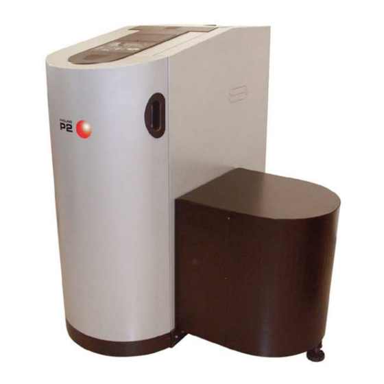
- Page 2 Introduction Dear Customer, Congratulations on choosing a quality product from FRÖLING. The FRÖLING P2 Pellet Boiler is a state-of-the-art design that conforms to all currently applicable standards and testing guidelines. Please read and observe the operating instructions and always keep them available in close proximity to the boiler.
-
Page 3: Table Of Contents
Contents 1 Product Overview 2 Safety 2.1 Safety Information 2.2 Permitted uses 2.2.1 Permitted fuel ....................9 2.2.2 Who can operate the boiler ................. 9 2.3 Design Information 2.3.1 Official approval and obligation to report ............10 2.3.2 Requirements for heating water................. 10 2.3.3 Ventilating the Boiler Room................ - Page 4 Contents 4 Lambdatronic P 3100 control system 4.1 Heating times table 4.2 Display values 4.2.1 Modes ......................25 4.2.2 Operating statuses....................26 4.3 Changing parameters and values 4.4 Menus 4.4.1 Settings menu....................28 Setting boiler temperature ................28 Set storage tank temperatures ................28 Set DHW tank temperatures................28 Setting heating times ..................29 Allocating heating times to heating circuits............29 Setting the runtime of the ash screw ..............30...
- Page 5 Contents 7 Installers and service technicians 7.1 Connection layout of the boards 7.2 Connection instructions 7.2.1 Mains connection ..................... 50 7.2.2 Heating circuit pumps for floor or wall heating............. 50 7.2.3 Jumper setting for solar control ................. 51 7.2.4 Flue gas sensor ....................51 7.2.5 Remote control....................
-
Page 6: Product Overview
Product Overview Product Overview Key switch for screw discharge 6, 7 22 23 24 25 26 Page 6 B0190806... - Page 7 Product Overview Pos. Component Symbol P2 Pellet Boiler with heat-exchanger Stoker assembly for screw discharge Stoker assembly for suction unit discharge Key switch to lock screw outputs of the pellet module (only for screw discharge) Additional insulating door for reduced heat radiation Combustion chamber door with viewing window Ashcan with wheels and handle (ash screw module) Ash drawer, front and rear (ash drawer module);...
-
Page 8: Safety
Safety Safety Information Safety Safety Information Non-permitted use! Incorrect use of the boiler can cause severe injuries and damage! The instructions and information provided in the instructions should be observed! Details on procedure for operation, maintenance and cleaning, as well as troubleshooting for the boiler are included in the individual instructions. -
Page 9: Permitted Uses
Safety Permitted Uses Permitted uses The boiler should only be operated when it is in full working order. It should be operated in accordance with the instructions, observing safety precautions, and you should ensure you are aware of the potential hazards. Ensure that any faults, which might impact safety are traced and removed immediately. -
Page 10: Design Information
Safety Design Information Design Information It is generally forbidden to carry modifications to the boiler or to change or deactivate safety equipment. In addition to the operating instructions and the applicable regulations for the country in which the boiler will be operated for installation and operation of the boiler system, all fire, police, and electrical regulations must be observed. -
Page 11: Heating System Installation/ Standards
Safety Design Information Rule of thumb: Provide a supply air cross-section of 2 cm per kW of boiler rated output, as per ÖNORM H 5170, but a total cross-section of at least 200 cm 2.3.4 Heating System Installation/ Standards The following standards govern the installation of heating systems: Applicable standards: §... -
Page 12: Chimney Connection / Chimney System
Install the draught limiter directly under the mouth of the flue line, as there is always low pressure there. Boiler data for constructing the flue gas system Component Unit P2-10 P2-15 P2-20 P2-25 Flue gas temperature °C Flue gas mass flow... -
Page 13: Safety Devices
Safety Safety Devices Safety Devices STOP key In case of overheating, shut down the boiler The pumps continue to run! Always end heating with the STOP key. Never use the main switch. Key switch (for screw Disengages power from the combustion discharge) unit’s drive components. -
Page 14: Devices For Preventing The Boiler From Overheating
Safety Safety Devices 2.4.1 Devices for preventing the boiler from overheating Thermal discharge safety device At around 100 °C a valve opens and sends cold water to the safety heat-exchanger to decrease the temperature. Safety Temperature Limiter STL Stops combustion at a max. boiler temperature of 100 °C. The pumps continue to run! As soon as the temperature has gone back down, the STL (1) can be mechanically unlocked. -
Page 15: Other Risks
Safety Other risks Other risks Do not touch the hot surface! Hot parts and the flue pipe can cause serious burns! Protective gloves should generally be worn when working on the boiler. Only operate the boiler using the handles provided for this purpose. -
Page 16: Emergency Procedure
Safety Emergency procedure Emergency procedure 2.7.1 System overheating If the system overheats and the safety devices fail to operate, proceed as follows: Keep all the doors on the boiler closed. Turn off the boiler with the Under no circumstances use the main switch! Open all mixer taps, switch on all pumps. -
Page 17: Operating The System
Operating the System Initial startup Operating the System Initial startup Initial startup should be carried out with an authorised installer or with Fröling customer services. The individual steps of the initial setup procedure are explained in the chapter on “Installers and service technicians” Page 59, 7.4 Initial startup If condensation escapes during the initial heatup phase, this does not indicate a fault. -
Page 18: Heating Up The Boiler
Operating the system Heating up the boiler Heating up the boiler 3.3.1 Switching on the system Switch on the main switch on the controls After the system check by the controls, the system is ready for operation 3.3.2 Switching on the boiler All selector switches must be set to “Auto”. -
Page 19: Emergency (Firewood) Operation
Operating the system Heating up the boiler Emergency (Firewood) Operation The P2 Pellet Boiler allows for emergency manual operation using firewood. This requires the “insert set for emergency firewood operation.” consisting of: - 1 x insertion grate (1) - 1 x cover plate (2) - 4 x combustion chamber guards (3) A properly functioning thermal discharge safety device is obligatory! -
Page 20: Filling The Combustion Chamber With Firewood
Operating the system Heating up the boiler Exchange the guide plate and replace as shown Put the steel cover onto the guide plate The combustion gases path over the guide plates is blocked. Hang 2 chamber guards each on the left and right in the combustion chamber on the bolts provided Insert the grate... -
Page 21: Modifying The Boiler For Normal Operation
Operating the system Heating up the boiler E N T E R Press the Mode A question mark appears Winter operation The value can be changed Press the key until firewood operation is shown on the display E N T E R Press the An arrow appears Firewood operation has been... -
Page 22: Lambdatronic P 3100 Control System
Lambdatronic P 3100 control system Menu overview Lambdatronic P 3100 control system Winter Operation Boiler temp. Set boiler temperature Heating Storage tank Error display Store temp. Heating circuit release Store up. min. temp. Boiler temp. Flue gas temp. Error list ID Fan Residual O2 DHW tank... -
Page 23: Heating Times Table
Lambdatronic P 3100 control system Display messages Heating times table Heating phase Heating phase Heating phase 1 Heating phase 2 Start Start Start Start Heating Heating prog. 1 prog. 8 Heating Heating prog. 2 prog. 9 Heating Heating prog. 3 prog. -
Page 24: Display Values
Lambdatronic P 3100 control system Display messages Display values After the main switch has been switched on and the control system has carried out the system check, the display shows the standard readout with the mode and operating status. Mode Winter operation Burner Off Operating status... -
Page 25: Modes
Lambdatronic P 3100 control system Display messages 4.2.1 Modes Winter operation The boiler controls the heating and hot water heating according to the timed program settings. There is no reduction in temperature the boiler stays at the same temperature and maintains a constant burn. Summer operation The boiler only controls the hot water heating according to the timed program settings. -
Page 26: Operating Statuses
Lambdatronic P 3100 control system Display messages 4.2.2 Operating statuses Preparation The induced draught fan is switched on. Heating up The combustion bowl is filled with pellets. The supply air fan, the induced draught fan and the igniter are turned on. Pre-heating The pellets are pre-warmed with the fan-assisted ignition and a bed of embers is formed. -
Page 27: Changing Parameters And Values
Lambdatronic P 3100 control system Menus and parameters Changing parameters and values Values are changed as follows: Save value and go back E N T E R Unlock parameter for processing Larger E N T E R Boiler temp. Boiler temp. should be 70°... -
Page 28: Settings Menu
Lambdatronic P 3100 control system Menus and parameters 4.4.1 Settings menu In the “Settings” operating menu the most important parameters and values for the system can be changed: Setting boiler temperature Boiler temp. Boiler temp. should be 80°C The boiler temperature is regulated to this temperature Set storage tank temperatures Storage tank... -
Page 29: Setting Heating Times
Lambdatronic P 3100 control system Menus and parameters Setting heating times Heating times Heating prog. 1 ... Heating phase 1 start 06:00 Lowered outside the specified heating times. Heating phase 1 end 11:00 Heating phase 2 start 15:00 Heating phase 2 end 23:00 Heating prog. -
Page 30: Setting The Runtime Of The Ash Screw
Lambdatronic P 3100 control system Menus and parameters Setting the runtime of the ash screw Pellet feed unit Ash screw Runtime Runtime of the ash screw Setting the pellet filling time Outfeeder Start time for 1st filling 15:00 1. Start time for filling. This is only carried out if the fill level in the container is under 85%. -
Page 31: Boiler Maintenance
Boiler maintenance Inspection, cleaning and maintenance Boiler maintenance Working on electrical components. Serious injuries from electric shocks! Work on electrical components should only be carried out by authorised technicians! Do not carry out maintenance when the boiler is hot! Hot parts and the flue pipe can cause serious burns! Protective gloves should generally be worn when working on the boiler. -
Page 32: Inspection, Cleaning, And Maintenance
Boiler maintenance Inspection, cleaning and maintenance Inspection, cleaning, and maintenance Regular cleaning of the boiler extends its life and is a basic requirement for smooth running. So clean the boiler regularly! 5.1.1 Inspection Checking the combustion chamber and pellet burner Check the boiler regularly for dirt: Shut down the boiler using the key and allow it to cool down... -
Page 33: Emptying The Ash Drawer (P2 Ash Drawer Module)
Boiler maintenance Inspection, cleaning and maintenance Emptying the ash drawer (P2 ash drawer module) Loosen the star-shaped screw knob on the front ash drawer by turning it to the left Pull out the front ash drawer Insert the ash drawer hook (provided) at the rear cross handle of the ash drawer Take the ash drawer to the emptying location Only dispose of the ash if there are no hot embers left and the... -
Page 34: Cleaning The Pellet Burner
Boiler maintenance Inspection, cleaning and maintenance Cleaning the pellet burner Open the insulating door and combustion chamber door Remove the combustion mount Tip the combustion mount The ash falls past the pellet burner and into the ashcan Clean the pellet burner using the ash scraper The slit must be free of ash! Checking the thermal discharge safety device... -
Page 35: Checking The System Pressure
Boiler maintenance Inspection, cleaning and maintenance Checking the system pressure Read off the system pressure on the pressure gauge The value must be over the pre- stressed pressure of the expansion tank by 20% Expansion tank operating instructions If the system pressure drops, refill the water If this occurs frequently, the heating system does not have a... -
Page 36: Clean The Flue Gas Sensors
Boiler maintenance Inspection, cleaning and maintenance Clean the flue gas sensors Remove the insulating cover Page 35, Checking the heat- exchanger and flue gas collection chamber Release the threaded pin and remove the sensing element from the flue gas pipe Wipe off the flue gas sensor with a clean cloth Slide in the flue gas sensing... -
Page 37: Clean The Smoke Flue Pipe
Boiler maintenance Inspection, cleaning and maintenance Clean the smoke flue pipe Clean the connecting pipe between the boiler and the chimney regularly with a chimney sweeping brush Depending on the layout of the flue pipes and the chimney draught cleaning yearly may not be enough! Checking the draught controller flap and explosion flap Check the draught controller flap and explosion flap for ease of operation... -
Page 38: Maintenance Agreement / Customer Services
Boiler maintenance Inspection, cleaning and maintenance Maintenance Agreement / Customer services Guarantee a long service-life with a service agreement! Regular maintenance and servicing by a heating specialist will ensure a long, trouble-free service life for your heating system. Regular servicing will ensure that your system stays environment- friendly and operates efficiently and cost-effectively. -
Page 39: Troubleshooting
Troubleshooting Troubleshooting General faults in power supply Error Cause of error Error correction Nothing is shown on the General power failure display FI circuit breaker or line Switch on the FI circuit breaker or line No power to the controls protection is switched off protection Main switch is turned off... -
Page 40: Faults With A Fault Message
Troubleshooting Faults with a fault message If a fault has occurred and has not yet been cleared: Status LED (1) flashes red A fault message is shown on the display (2) An internal distinction is made between 3 types of message: Warning (W) Boiler continues running Error (E) -
Page 41: Error Message List
Troubleshooting Error message list Error texts in alphabetical order: Error text Code Type Cause of error Error correction • Outdoor sensor temp. Sensor signal damaged Check sensor and sensor cable false • DHW temp. false Sensor signal damaged Check sensor and sensor cable •... - Page 42 Troubleshooting Error text Code Type Cause of error Error correction Pressure monitor comb Excess pressure in Acknowledge error chamb combustion chamber NOTE: After acknowledging the error, error correction starts immediately. Keep the doors of the boiler closed! After error correction starts, check if the induced draught fan is running CAUTION! In case of defective induced draught fan inform the heating engineers or Fröling customer services!
- Page 43 Troubleshooting Error text Code Type Cause of error Error correction • Store temp. up. false Sensor signal damaged Check sensor and sensor cable • Store temp. mid. false Sensor signal damaged Check sensor and sensor cable Outfeed system error Gravity shaft level sensor (with screw discharge unit) does not recognise any material for 60 minutes:...
- Page 44 Troubleshooting Error text Code Type Cause of error Error correction Check/clean outfeed For manual universal system (for manual suction systems: universal suction systems) The MAX sensor is not reached after 15 minutes of suction at the probe: • No pellets at the suction Refill pellets in store For information on errors in probe...
- Page 45 Troubleshooting Error text Code Type Cause of error Error correction “Insufficient safety time The value for the parameter, elapsed”. “Min. boiler flue temp dif.” fell Acknowledge error below the specified level for longer than the safety time. NOTE: After acknowledging the error, error correction starts immediately.
- Page 46 Troubleshooting Error text Code Type Cause of error Error correction Safety time Oxygen content is greater O2 too high than the “Remaining O2 shut Acknowledge error down” parameter - duration longer than safety time (in the HEATING state): NOTE: After acknowledging the error, error correction starts immediately.
- Page 47 Troubleshooting Error text Code Type Cause of error Error correction Ignition failed Boiler remains in “IGNITE” state longer than the Acknowledge error “Ignition time max”: NOTE: After acknowledging the error, error correction starts immediately. Keep the doors of the boiler closed! After error correction starts, check if the induced draught fan is running CAUTION! In case of defective induced draught fan inform the...
-
Page 48: Installers And Service Technicians
Installers and service technicians Electrical Connection Installers and service technicians Connection layout of the boards View of lower level Lambda Sensor 4 board Sensor 5 3100 whi 12VAC Lambda whi 12VAC (optional) probe black Pump 3 Pump 3 3100 Power supply of motherboard control User e.g.: RGB,... - Page 49 Installers and service technicians Electrical Connection View of upper level RC 2 Remote control 2 RC 1 Remote control 1 OF 2 Ribbon cable Outfeed sensor 2 from motherboard OF 1 Outfeed sensor 1 ES 1 External sensor 1 Sensor 6 Sensor 7 OPEN Mixer 2...
-
Page 50: Connection Instructions
Installers and service technicians Electrical Connection Connection instructions Working on electrical components. Serious injuries from electric shocks! Work on electrical components should only be carried out by authorised technicians! 7.2.1 Mains connection Cable to pellet module Lambdatronic P 3100 Feed cable L, N, PE power supply for the whole control, cable width 2.5 mm²... -
Page 51: Jumper Setting For Solar Control
Installers and service technicians Electrical Connection 7.2.3 Jumper setting for solar control With the solar control the mixer 3 and mixer 4 outputs are used as pump outputs. The jumpers on expansion board 2 must be set as shown in the table: Jumpers on expansion board 2 System Set JP1... -
Page 52: Rbg 3100 Room Console
Installers and service technicians Electrical Connection 7.2.6 RBG 3100 room console If the room console has a cable length of over 5 m shielded cable is obligatory. The cable must not be longer than 25 m. The RBG 3100 console also includes a room sensor (set remote control to “Y”), which sends the current room temperature to the control. -
Page 53: Heating Circuit Pump 0 / Oil - Oil Burner Contact
Installers and service technicians Electrical Connection 7.2.8 Heating circuit pump 0 / Oil - oil burner contact The HCP 0 / oil connection can be used either for heating circuit pump 0 or as an burner relay depending on the system settings. Connecting a HCP 0 up to 2 Ampere: Lambdatronic P 3100... -
Page 54: Connection Layout Of The Pellet Module
Clos. Fault pot. Free contact Opener Stoker thermostat Only for devices without pellet valve Stoker To motherboard: “Device extension” Discharge screw Ash screw MAX level (day store) Heat exchanger drive brown Gravity shaft white level sensor blue Suction unit black Combustion chamber Ignition white... -
Page 55: Pellet Module With Suction System
Clos. Fault pot. Free contact Opener Stoker thermostat Only for devices without pellet valve Stoker To motherboard: Discharge screw “Device extension” (only for screw suction systems) Ash screw brown MAX level white (day store) blue Heat exchanger drive brown blockage sensor white (only for screw suction Suction unit... -
Page 56: Overview Of Connected Components
Installers and service technicians Electrical Connection 7.3.3 Overview of connected components CLOSER FAULT OPENER STOKER THERMOST. HEAT EXCH. STOKER SCREW DRIVE M4 DISCHARGE SCREW SCREW HEAT EXCHANGER DRIVE SUCTION UNIT IGNITION 230 VAC POWER SUPPLY ASH SCREW M5 SUCTION UNIT M3 FRÖLING DEVICE EXTENSION MAX LEVEL S1... -
Page 57: Connection Instructions For Komfort Pellet Box
Installers and service technicians Electrical Connection 7.3.4 Connection instructions for Komfort pellet box With the automatic universal suction system the Komfort pellet box is linked to the control board with a flexible cable (5x 0.75mm², flexible, e.g. YMM as per ÖVE-K41-5 or H05VV-F as per DIN VDE 0281-5). This is a 24V control line. -
Page 58: Boiler Release
Installers and service technicians Electrical Connection 7.3.5 Boiler Release When setting the system selection, the parameter “Boilerlaunch in av” is preset to enable an external floating release or start contact. Boilerlaunch in av This is set if boiler release input is available. As long as the contact is closed, the controls operate according to the specified parameters. -
Page 59: Initial Startup
Installers and service technicians Initial startup Initial startup Initial startup should be carried out with an authorised installer or with Fröling customer services. 7.4.1 Turn on system After the boiler has been switched on at the main switch, the controls carry out a system check and show the standard readout on the display with mode and operating status. -
Page 60: Setting System Type
Installers and service technicians Initial startup Untrained operators may enter incorrect settings! Incorrectly set parameters at “Installer” and “Service” level can cause serious problems with boiler functioning! 7.4.3 Setting system type ERROR DISPLAY repeatedly E N T E R E N T E R MANUAL ANAL. -
Page 61: System 0
Installers and service technicians Initial startup System This table shows the variants, which are currently possible with the Lambdatronic 3100. There is a more detailed description in the Fröling energy system brochure. Permanently available Options System 0 System 1 System 2 System 3 System 4 System 5... -
Page 62: Checks Before First Heating Up
Installers and service technicians Initial startup Select the system according to the table above, and set on the controls. When the system has been selected, the display changes to the system parameters. The number of the following parameters depends on the system selected: ←... -
Page 63: Drives
Installers and service technicians Initial startup Drives Check that drives and servomotors are working Check the operating speed of the induced draught fan when the insulating door is closed under the limit it must operate at 35 - 40% Adjust using the “MIN Speed” parameter Check that the door contact switch is working correctly When the insulating door is open the induced draught fan runs at 100% speed. -
Page 64: Setting Sensor "Level Max
Installers and service technicians Initial startup Setting sensor “Level Max” In delivery configuration, the factory settings of the sensor are secured with a seal. Changes to the settings should only be carried out by qualified technicians. The monitoring LED (1) should only illuminate when identifying materials! If the monitoring LED is constantly lit, the sensitivity is set too high! -
Page 65: Setting Parameters
Installers and service technicians Initial startup NOTE for Uno/Eco/Komfort universal suction systems and bag silo systems: To fill the suction unit container set the “Fill” parameter in the “Manual operation” menu to “ON”. The suction system starts and the suction unit container is filled with fuel until the switch point of the level sensor is reached. -
Page 66: Lambdatronic P 3100 Parameter List
Installers and service technicians Parameter list - Lambdatronic P 3100 Lambdatronic P 3100 parameter list 7.5.1 Menu overview E N T E R Pressing the key once takes you from the basic readout to the first menu level, where the following menu items can be selected: Page 67, 7.5.2 Settings menu ERROR DISPLAY Page 39, 6 Troubleshooting... -
Page 67: Settings Menu
Installers and service technicians Parameter list - Lambdatronic P 3100 7.5.2 Settings menu Boiler temp..← ← ← ← Set boiler temperature 80° ← ← ← ← The boiler temperature is regulated to this temperature Shut down over If the boiler temperature exceeds the target value by 5°... - Page 68 Installers and service technicians Parameter list - Lambdatronic P 3100 Desired DHW tank When the specified temperature is reached in the DHW ... ← ← ← ← DHW tank 55°← ← ← ← temperature tank, the DHW tank loading pump switches off. Desired DHW tank 2 When the specified temperature is reached in DHW 55°←...
- Page 69 Installers and service technicians Parameter list - Lambdatronic P 3100 Oil boiler-Storage The minimum temperature difference between the oil ... ← ← ← ← 10°← ← ← ← Oil boiler temp diff boiler and storage tank which releases the oil boiler loading pump output.
- Page 70 Installers and service technicians Parameter list - Lambdatronic P 3100 Heating prog. Heating phase Heating times... ← ← ← ← Lowered outside of heating phases. 1... ← ← ← ← 1 start 06:00 Heating phase Only in conjunction with heating circuit control. 1 end 11:00 Heating phase...
- Page 71 ... ← ← ← ← Feed without ignition 75s← ← ← ← Ignition boiler goes to “pre-heating” status Factory settings: P2-10: 105s, P2-15: 95s, P2-20/25: Boiler in “Heating up” status: Speed during the ← Fan without ignition heating up phase Boiler in “Pre-heating”...
- Page 72 Adjustment to fan in use – do not change setting Fan speed at maximum output ← Fan MAX Factory settings: P2-10: 60%, P2-15: 65%, P2-20: 70%, P2-25: 75% If the flue gas temperature is above the specified 100% output from target value, fuel output should reach 100% (upper 100°←...
- Page 73 Installers and service technicians Parameter list - Lambdatronic P 3100 1. Start time for 1. Start time for filling. This is only carried out if the fill ← ← ← ← Outfeed 15:00← ← ← ← automatic filling level in the container is under 85%. Only for universal 2.
-
Page 74: Error List Menu
Installers and service technicians Parameter list - Lambdatronic P 3100 You can select from: Winter operation Summer operation Mode: Winter operation Transitional operation Firewood operation (EMERGENCY OPERATION) Cleaning Console 3100: possible allocation combinations Normal Master Normal: Allocation and control of this heating circuit only RBG 3100 Master: Allocation to respective heating circuit, control of Alloc.: 14... -
Page 75: Manual Operation Menu
Installers and service technicians Parameter list - Lambdatronic P 3100 7.5.4 Manual operation menu Used for manual fuel feed to the burner and manual operation of heat exchanger motor and ash screw. ON← ← ← ← Manual fuel feed to burner MANUAL FUEL OFF←... -
Page 76: Manual Anal. Menu Out
Installers and service technicians Parameter list - Lambdatronic P 3100 7.5.6 Manual anal. menu OUT Used to test the digital outputs and is intended only for heating engineers. The display depends on the configuration. A 0%← ← ← ← ID fan Storage tank LPA 0% Storage tank loading pump DHW LP A 0%←... -
Page 77: Appendix
Appendix Manufacturer’s guarantee conditions Appendix Guarantee conditions Our sale and delivery conditions generally apply. These conditions have been made available to customers, and customers have been made aware of them at the time of order completion. You can also find the guarantee conditions in the enclosed guarantee certificate. -
Page 78: Declaration Of Conformity
Appendix Declaration of Conformity Declaration of Conformity EU DECLARATION OF CONFORMITY Product: Pellet boilers Types: Pellet boiler P2-10, Pellet boiler P2-15, Pellet boiler P2-20, Pellet boiler P2-25 EU Directives: 89/392/EEC Legal Regulations for Machinery 73/23/EEC Legal Regulations for Electrical Equipment:... -
Page 79: Your Notes
Your Notes Your Notes Fröling Heizkessel- und Behälterbau Ges.m.b.H, Industriestraße 12, A-4710 Grieskirchen, Austria Page 79 Tel +43 (0) 7248 606-0 Fax +43 (0) 7248 606-600 info@froeling.com www.froeling.com B0190806... - Page 80 Menu overview Lambdatronic P 3100 Winter Operation Boiler temp. Set boiler temperature Heating Storage tank Store temp. Heating circuit release Error display Store up. min. temp. Boiler temp. Flue gas temp. Error list ID Fan Residual O2 DHW tank Set DHW tank temp. Storage.up.
Need help?
Do you have a question about the P2-15 and is the answer not in the manual?
Questions and answers