Table of Contents
Advertisement
Quick Links
Advertisement
Table of Contents

Related Manuals for Snap-On Solus Ultra


Summary of Contents for Snap-On Solus Ultra
- Page 1 User Manual EAZ0075L19B Rev. B 1-H-18 UK...
- Page 2 End User License Agreement. The Snap-on Incorporated Software End User License Agreement may be provided with the diagnostic tool, and is available at: https://eula.snapon.com/diagnostics. Patent Information For a listing of Snap-on products that are protected by patents in the United States and elsewhere, visit: https://patents.snapon.com User Manual Information This manual includes information and images applicable with diagnostic software version 18.4 and later.
- Page 3 “See Quick Tips”. NOTE: Sample titles are listed below. Not all titles may be available for all diagnostic tools, and are subject to change. Snap-on® Training Solutions® - Training Videos (examples) Introduction and Navigation Global OBD-II...
- Page 4 Diagnostic Quick Tips - Video Series Snap-on Diagnostic Quick Tips videos are available at no charge on our website and on our YouTube channel. These videos are developed from real repair case studies to help professional technicians use diagnostic tools to solve specific vehicle problems (e.g.
- Page 5 Diagnostic Quick Tips - Video Series Snap-on® Training Solutions® - Diagnostic Quick Tips Videos (examples) Hyundai Blind Spot Detection System Chrysler HVAC Test Calibration Chrysler VVT System Cleaning Hyundai Occupant Detection System Reset Chrysler Wheel & Tire Calibrations Ignition Coil Current and Voltage Comparison...
-
Page 6: Table Of Contents
Contents Chapter 1: Using This Manual ....................5 Conventions..........................5 Bold Text ..........................5 Symbols ..........................5 Terminology ........................... 6 Notes and Important Messages ..................... 6 Procedures..........................6 Chapter 2: Introduction......................7 Functional Description ........................7 Technical Specifications ....................... 9 Control Keys .......................... - Page 7 Contents Connecting to a Vehicle......................22 Cables ..........................23 No Communication Message ....................23 Operations ..........................24 Codes Menu......................... 25 Data Display......................... 30 Functional Tests........................38 Troubleshooter ........................38 Exiting the Scanner ........................39 Chapter 6: OBD-II/EOBD ......................40 OBD Health Check ........................40 Global OBD II Code Check ....................
- Page 8 Safety Information For your own safety and the safety of others, and to prevent damage to the equipment and vehicles upon which it is used, it is important that the accompanying Important Safety Instructions be read and understood by all persons operating, or coming into contact with, the equipment. We suggest you store a copy near the unit in sight of the operator.
- Page 9 Safety Information Important Safety Instructions Safety messages contain three different type styles. Normal type states the hazard. • Bold type states how to avoid the hazard. • Italic type states the possible consequences of not avoiding the hazard. • An icon, when present, gives a graphical description of the potential hazard. Example: Risk of unexpected vehicle movement.
-
Page 10: Chapter 1 Using This Manual
Using This Manual Chapter 1 This manual contains tool usage instructions. Some of the illustrations shown in this manual may contain modules and optional equipment that are not included on your system. Contact your sales representative for availability of other modules and optional equipment. 1.1 Conventions The following conventions are used. -
Page 11: Terminology
Using This Manual Conventions 1.1.3 Terminology The term “select” means highlighting a button or menu item and pressing the Accept, OK, Yes, or other similar button to confirm the selection. Example: Select Brightness. • The above statement abbreviates the following procedure: 1. -
Page 12: Chapter 2 Introduction
Introduction Chapter 2 The Scanner interfaces with the electronic control system of a vehicle to retrieve diagnostic trouble codes (DTCs), access serial data stream information, and command bi-directional tests. Various vehicle control systems, such as engine, transmission, and antilock brake system (ABS), are readily diagnosed using this scan tool. - Page 13 Introduction Functional Description 1— DC Power Supply Input Port 2— Battery Status Indicator LED (light emitting diode) 3— Mini USB Client Port 4— Micro secure digital (uSD) Card Port 5— Data Cable Port Figure 2-2 Top view 1— Collapsible Stand (closed) 2—...
-
Page 14: Technical Specifications
Introduction Technical Specifications 2.2 Technical Specifications Touch Screen Resistive Touch Panel Display: 7.0 inch diagonal, Color LCD 800 x 480 resolution SWVGA Battery: Rechargeable lithium-ion battery pack Approximately 2 hour run time Approximately 5 hour charge time DC Jack Operating Voltage 10V and 28V DC Dimensions: Width:... -
Page 15: Control Keys
Introduction Control Keys 2.3 Control Keys There are five control keys located on the right side of the unit near the handgrip: Icon Description Selects a menu or program, advances to the Accept, Yes next screen, or provides a yes answer to a question on the screen. -
Page 16: Cancel (N/X) Key
Introduction Power Sources 2.3.3 Cancel (N/X) Key The N/X key is used to do the following: To exit a menu or program. • To close an open list and return to the previous menu. • To answer “No” when a Yes or No choice is given. •... -
Page 17: Ac Power Supply
Introduction The Stand 2.4.2 AC Power Supply The scan tool can be powered from a standard wall socket using the AC power supply and power adapter. The jack on the output cable of the AC power supply attaches to the DC power supply input port on top of the scan tool. -
Page 18: Chapter 3: Getting Started
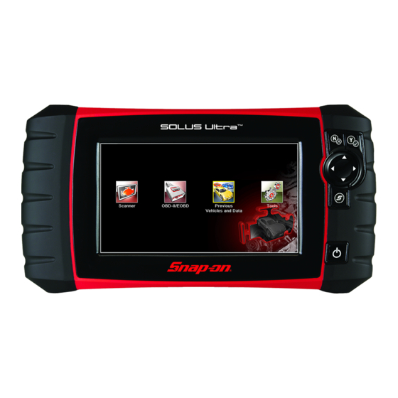
Getting Started Chapter 3 Make sure the scan tool has a charged battery pack, is connected to a powered vehicle data link connector (DLC), or is connected to an AC power supply. 3.1 Powering Up Press the Power key on the front of the unit to switch the scan tool on. The system boots up, then opens the Home screen (Figure 3-1). -
Page 19: Home Screen Buttons
Getting Started Home Screen The titlebar, which runs across the top of the screen, provides information about the current screen or a description of the defined test vehicle. The title bar contains no selectable items. A graphic indicator at the right edge of the toolbar shows the status of the tool power supply: Table 3-1 Power supply icons Icon Definition... -
Page 20: The Demonstration Program
Getting Started Powering Down 3.2.2 The Demonstration Program The Scanner demonstration program allows you to become familiar with many of the test capabilities of the tool without connecting to a vehicle. The demonstration contains actual data captured while driving a 2001 Chevrolet Tahoe. To start the demonstration program: 1. -
Page 21: Chapter 4 Navigation
Navigation Chapter 4 This chapter describes the scan tool screen layout, and to make selections using screen menus and buttons, and the various types of messages that display while using the tool. 4.1 Screen Layout Scan tool screens (Figure 4-1) typically include the following sections: 1—... -
Page 22: Toolbar
Navigation Screen Layout A communication icon displays to the left of the power source indicator whenever the scan tool is actively communicating with a test vehicle or a personal computer. 4.1.2 Toolbar The toolbar, located under the title bar, contains a number of selectable buttons that control tool functions. -
Page 23: Main Body
Navigation Screen Layout Table 4-1 Data toolbar buttons (part 2 of 2) Button Icon Function Opens the tools menu, which allows Tools you to adjust basic tool settings. Moves back one frame at a time when viewing recorded or paused data. Hold Previous Frame the button down to keep moving back through the data. -
Page 24: Screen Messages
Navigation Screen Messages Tap the arrowheads at the ends of the scroll bars to move through the data in the direction of the arrow one page at a time. Selecting an arrowhead that points to a line moves you directly to the beginning or end of the data. -
Page 25: Chapter 5 Scanner
Scanner Chapter 5 The Scanner establishes a data link to the electronic control systems of the vehicle being serviced. This allows you to retrieve diagnostic trouble codes (DTCs) view live data parameters, and perform tests. Scanner testing requires connecting the scan tool to the test vehicle using the data cable and test adapters. - Page 26 Scanner Vehicle Identification 3. Select the year of the test vehicle from the menu. A list of vehicle types or models displays. Several selections may be required to identify the vehicle type and model, follow the screen prompts and enter the required information. A confirmation screen displays once all the required data has been entered (Figure 5-2).
-
Page 27: Alternative Vehicle Identification
Scanner Connecting to a Vehicle NOTE: Only the systems available for testing on the identified vehicle are included in the list. The identification sequence is now complete. 5.1.1 Alternative Vehicle Identification Occasionally, you may identify a test vehicle that the Scanner does not recognize, the database does not support, or has some unique characteristics that prevent it from communicating with the Scanner through the normal channels. -
Page 28: Cables
Scanner Connecting to a Vehicle 5.2.1 Cables One of two data cables, one for OBD-II/EOBD compliant vehicles and an optional one for non-OBD-II/EOBD models, is used to connect the scan tool to the test vehicle. The 26-pin end of either cable attaches to the data cable port on the top of the scan tool. The connector is secured with captive screws. -
Page 29: Operations
Scanner Operations 5.3 Operations The Scanner allows you to establish a data link to the electronic control systems of the vehicle being serviced in order to view live data parameters and perform tests. You can use selected functional tests, get troubleshooting tips, and get vehicle-specific trouble codes for various vehicle control systems such as engine, transmission, antilock brake system (ABS) and more. -
Page 30: Codes Menu
Scanner Operations System Tests—provides specific subsystem testing. Performing these tests is similar to • functional tests. Generic Functions—lets you access certain available Generic OBD II functions from a • proprietary menu (1996 and newer vehicles only). Troubleshooter—provides step-by-step procedures, integrating parameter data and •... - Page 31 Scanner Operations Figure 5-6 Sample code list Clear Codes The Scanner clears emissions-related codes from the control module memory on some vehicles. If this function is not available on the test vehicle, Clear Codes does not appear as a menu option. NOTE: Clear Codes is also available from OBD-II Health Check (see “OBD Health Check“...
- Page 32 Scanner Operations IMPORTANT: PRE / POST Scan Importance - As many systems do not turn on the check engine light or other indicator, performing a vehicle code scan before making any repairs may help in troubleshooting, by identifying possible unknown issues that may be related to the present symptoms. Performing pre and post scans also allows you to record in report format the pre-condition of the vehicle and compare the post scan after work is complete to confirm the repairs were completed properly.
- Page 33 Scanner Operations Depending on the vehicle, Code Scan (if supported) may be available from the Systems menu. Selecting Code Scan starts an active scan of vehicle control modules, and opens the Code Scan results screen (Figure 5-8). A progress indicator is shown at the top indicating the active scanning progress.
- Page 34 Scanner Operations Figure 5-9 System icon (opens Main Menu) Saving Codes, and Code Scan Results) When using the code scan feature, or when viewing individual system codes (e.g. engine, transmission) selecting the Save icon from the toolbar saves the results as a data file. The saved file(s) can be viewed using two methods: On the diagnostic tool - See “View Saved Data“...
-
Page 35: Data Display
Scanner Operations 5.3.2 Data Display Select Data to view live datastream parameters from the vehicle ECM. In data display mode the screen has a toolbar and a main body (Figure 5-10). Figure 5-10 Sample data display screen Toolbar The buttons on the toolbar operate as shown in Table 4-1 on page17 while viewing data. - Page 36 Scanner Operations On the toolbar, the Pause button replaces the Record button and the Previous Frame and Next Frame buttons display. A frame counter displays at the top of the main body of the screen, and a vertical line indicates your position in the graphs (Figure 5-11).
- Page 37 Scanner Operations Sorting Data The Sort button on the toolbar allows you to arrange the parameter list three ways Factory Sort—lists parameters in the order they are transmitted by the ECM • A-Z Sort—lists parameters alphabetically in ascending order • Z-A Sort—lists parameters alphabetically in descending order •...
- Page 38 Scanner Operations The toolbar buttons provide options for selecting and deselecting which parameters to include or remove from the custom data list: Button Description Select/Deselect, use to mark individual parameters to hide or display. Select All/Deselect All, use to hide or display all of the parameters in the list.
- Page 39 Scanner Operations Figure 5-12 Sample 4 Graph view screen Any previously set conditions, such as held data or locked lines of data, remain in effect when the screen view is changed. Locking Parameters Use the Lock/Unlock button to lock selected lines of the data in place and prevent them from scrolling, or to release previously locked lines of data.
- Page 40 Saved files can also be downloaded from the scan tool to a personal computer (PC) through the Mini USB port. Once connected to the PC, SOLUS Ultra files can be printed, transferred, and copied using ShopStream Connect. ShopStream Connect is a PC application that creates an interface between the scan tool and a PC.
- Page 41 Scanner Operations Figure 5-14 Sample save dialog box The Shortcut key can be programmed to perform the Save Screen or Save Movie function. See “Configure Shortcut Key“ on page 54 for details. Setting Trigger Levels The PID Trigger button on the toolbar allows you to configure the scan tool to automatically capture data when a parameter value crosses a threshold value.
- Page 42 Scanner Operations Figure 5-15 Sample trigger set screen 4. Tap the plus (+) and minus (–) buttons on the toolbar, or use the up b and down d arrow keys to position the upper trigger level to where you want it on the graph. 5.
-
Page 43: Functional Tests
Scanner Operations 5.3.3 Functional Tests The Functional Tests selection is used to access vehicle-specific subsystem and component tests. Available tests vary by manufacturer, year, and model, and only the available tests display in the menu. There are four general types of functional test operations: Information Tests—are read-only tests, like selecting “VIN”... -
Page 44: Exiting The Scanner
Scanner Exiting the Scanner Information is organized into a series of diagnostic tips that are designed to quickly lead you to the root cause of a particular problem. The tips are vehicle-specific, which means only tips that relate to the identified vehicle are presented. Selecting opens a menu that typically includes: Code Tips—provides detailed information on setting conditions, testing, and interpreting test •... -
Page 45: Chapter 6: Obd-Ii/Eobd
OBD-II/EOBD Chapter 6 This Home screen option allows you to access Generic OBD-II/EOBD Scanner tests without completing a vehicle identification. This option presents a quick way to check for diagnostic trouble codes (DTCs), isolate the cause of an illuminated malfunction indicator lamp (MIL), check monitor status prior to emissions certification testing, verify repairs, and perform a number of other services that are emissions-related. -
Page 46: Global Obd Ii Code Check
OBD-II/EOBD OBD Health Check 6.1.1 Global OBD II Code Check The Code Check displays stored emission related generic DTCs reported by the ECM. Selecting this option opens a submenu with two choices: Codes and Pending Codes. Select an option to display the code list. -
Page 47: Global Obd Ii Clear Codes
OBD-II/EOBD OBD Health Check 6.1.2 Global OBD II Clear Codes This option is used to clear all emission related diagnostic data, such as DTCs, freeze frame data, and test results, from the memory of the selected ECM. Although OBD-II/EOBD only displays generic OBD-II/EOBD data, clearing codes erases all of the stored data, including any enhanced codes and freeze frame information. -
Page 48: Obd Diagnose
OBD-II/EOBD OBD Diagnose To locate a vehicle diagnostic connector: 1. Select Connector Information from the System menu. A list of vehicle manufacturers displays. 2. Select a manufacturer from the list. A list of models available from the selected manufacturer displays. 3. - Page 49 OBD-II/EOBD OBD Diagnose To perform an OBD-II/EOBD Test: 1. Select Start Communications from the OBD-II/EOBD menu. A vehicle type options list displays: 12V Light Duty Vehicle – 24V Heavy Duty/Goods Vehicle – 2. Select an option from the vehicle type list. A connection message displays.
- Page 50 OBD-II/EOBD OBD Diagnose Readiness Monitors Use this menu item to check the readiness of the monitoring system. If a monitor system is not supported, it is not displayed. Scroll, if needed, to view the entire list of monitors (Figure 6-3). Selecting Readiness Monitors opens a submenu with two choices: Monitors Complete Since DTC Cleared—displays the results of all monitor tests that have •...
- Page 51 OBD-II/EOBD OBD Diagnose ($03) Display Trouble Codes This is used to display any stored emission related DTCs reported by the ECM. The display is similar to a Scanner code display, but does not include any enhanced DTCs. ($04) Clear Emissions Related Data This item is used to clear all emission related diagnostic data, such as DTCs, freeze frame data, and test results, from the memory of the selected ECM.
- Page 52 OBD-II/EOBD OBD Diagnose ($06) Specific Monitored Systems This selection opens a menu of available test results on monitored systems. The data available is for specific systems and components that the onboard diagnostic system either continuously monitors, such as misfire, or non-continuously monitors, such as the catalyst system. Making a selection displays the test results.
-
Page 53: Select Communication Protocol
OBD-II/EOBD OBD Diagnose ($0A) Emission Related DTC with Permanent Status This selection displays a record of any “permanent” codes. A permanent status DTC is one that was severe enough to illuminate the MIL at some point, but the MIL may not be on at the present time. -
Page 54: Chapter 7 Previous Vehicles And Data
Previous Vehicles and Data Chapter 7 The Previous Vehicles and Data Home screen selection allows you to quickly configure the scan tool to the identity of a recently tested vehicle, and to access saved data files. A menu with three options opens when Previous Vehicles and Data is selected: Vehicle History •... -
Page 55: View Saved Data
Previous Vehicles and Data View Saved Data A connection message displays. 5. Connect the data cable to the vehicle, then select OK or press Y/a to continue. The menu for the last system tested on the selected vehicle displays. 7.2 View Saved Data Selecting the View Saved Data menu option opens a list of all the data movies and screen images that are stored in the scan tool memory. -
Page 56: Viewing Codes And Code Scan Results
Previous Vehicles and Data View Saved Data 7.2.1 Viewing Codes and Code Scan Results When code scan or single system code results are saved, they are saved in (.XML) file format (Figure 7-3). Figure 7-3 Typical - Code Results (.XML) file The saved (.XML) file(s) can be viewed using these methods: On the diagnostic tool - See "Viewing Code Results on the Diagnostic Tool‚"... -
Page 57: Delete Saved Data
Previous Vehicles and Data Delete Saved Data Viewing Code Results on the Diagnostic Tool Selecting a system code or a code scan results file from your saved file list (Figure 7-4), opens the file onscreen. When opened, the (.XML) file displays basic vehicle information and a list of DTCs with a brief description of each. -
Page 58: Chapter 8 Tools
Tools Chapter 8 The Tools option on the home screen is used to configure the scan tool for your personal preferences. Tap the Tools button to open a menu of options. Figure 8-1 Sample Tools menu 8.1 Tools Menu The following options are available from the Tools menu: Connect To PC—use to transfer and share files with a personal computer (PC) •... -
Page 59: Configure Shortcut Key
Tools Tools Menu To connect the diagnostic tool to a PC: 1. Connect the supplied USB cable to the diagnostic tool and then to the PC. A USB cable, supplied with your diagnostic tool, is used to connect the diagnostic tool to the PC. -
Page 60: System Information
Tools Tools Menu 8.1.3 System Information The System Information option lets you view configuration information for your scan tool. To display the System information screen: 1. Select Tools from the Home screen to open the menu. 2. Select System Information from the menu. The System Information screen displays. - Page 61 Tools Tools Menu Display options include: "Brightness‚" on page 56—adjusts the intensity of the screen back lighting. • "Color Theme‚" on page 57—changes the background color of the screen display. • "High Contrast Toolbar‚" on page 57—enhances toolbar graphics for poor lighting conditions. •...
- Page 62 Tools Tools Menu Color Theme This option allows you to select between a white and black background for the screen. The black background can be beneficial when working under poor lighting conditions. Selecting opens a menu with two choices: Day Theme (white background) and Night Theme (black background).
- Page 63 Tools Tools Menu Selecting opens a menu with two choices; Color Toolbar and High Contrast Toolbar. Select and a “please wait” message displays followed by the Home screen. The new setting is now active. Font Type This option allows you to select between standard and bold faced type for the display screen. Bold type makes screen writing more legible under poor lighting or bright sunlight conditions.
- Page 64 Tools Tools Menu Figure 8-7 Sample calibration screen 4. Touch each box on the screen as it displays. The display returns to the Settings menu once the screen calibration procedure is complete. IMPORTANT: It is critical to complete the touch screen calibration sequence once it has begun. Never power down the unit while a screen calibration is in process, serious damage to the unit may result.
- Page 65 Tools Tools Menu Figure 8-8 Sample Clock Settings screen 4. Tap the up (+) button on the screen or press the up (b) key on the keypad to incrementally increase the number in the highlighted field. Tap the down (–) button on the screen or press down (d) on the keypad to incrementally decrease the number.
- Page 66 Tools Tools Menu Date Format This option allows you to select how date information is displayed. Select from: (MM_DD_YYYY)—Month, Day, Year • (DD_MM_YYYY)—Day, Month, Year • (YYYY_MM_DD)—Year, Month, Day • Make a selection, then tap the Back button or press the N/X key to return to the menu. Configure Scanner This option determines whether or not the scales are displayed on the data graphs when using the Scanner.
- Page 67 Tools Tools Menu Configure Units Selecting opens a dialog box that allows you to choose between US customary or metric units of measure for temperature, vehicle speed, air pressure, and other pressures. Figure 8-10 Sample Configure Units menu To change the units setup: 1.
-
Page 68: Chapter 9 Maintenance
Maintenance Chapter 9 This chapter covers how to care for your scan tool. 9.1 Cleaning and Inspecting the Scan Tool When using the scan tool perform the following tasks to keep it in top shape: Check the housing, wiring, and connectors for dirt and damage before and after each use. •... -
Page 69: Battery Safety Guidelines
If the battery pack no longer holds a charge, contact your sales representative to order a new one. IMPORTANT: Replace the battery pack with original Snap-on replacement parts only. To replace the battery pack: 1. Loosen the two captive screws that secure the battery pack to the back of the unit. -
Page 70: Disposing Of The Batteries
Maintenance Battery Service 1— Battery Cover 2— Captive Screws Figure 9-1 Battery pack replacement 9.2.3 Disposing of the Batteries Always dispose of a lithium-ion battery pack according to local regulations, which vary for different countries and regions. The battery pack, while non-hazardous waste, does contain recyclable materials. -
Page 71: Chapter 10 Shopstream Connect
ShopStream Connect Chapter 10 This chapter includes a brief introduction to some of the key features of the ShopStream Connect software. For detailed ShopStream Connect information and instructions, download the ShopStream Connect User Manual from our website: https://www.snapon.com/diagnostics/uk/User-Manuals.htm The ShopStream Connect™ (SSC) software is PC-based software that extends the capabilities of your diagnostic tool. -
Page 72: Ssc Main Screen
ShopStream Connect SSC Main Screen If the ShopStream Connect software does not open, open it from the Windows Start menu or use the ShopStream Connect shortcut icon on the Windows desktop (automatically created during installation). 10.2 SSC Main Screen The ShopStream Connect software will open automatically when you connect the diagnostic tool to your PC USB connection, Using SSC (Connecting to your PC)‚... -
Page 73: Scanner Dataviewer
ShopStream Connect Scanner DataViewer 6— Main display—shows stored data files details. NOTE: The files listed are sortable (ascending/descending) by clicking on the column tab at the top (e.g. File Name, Type, etc.) Sort preferences are saved when the ShopStream Connect program is closed. 7—... -
Page 74: Image Viewer
ShopStream Connect Image Viewer 10.4 Image Viewer SSC allows you to view and print .bmp, .jpg and .sps image files (screenshots) saved on your diagnostic tool, with your PC. NOTE: File extension types vary depending on the diagnostic tool. Not all the file extensions described here may be available on your diagnostic tool. -
Page 75: Printing The Code Scan Report
ShopStream Connect Printing the Code Scan Report 10.5 Printing the Code Scan Report To print the Code Scan Report, the saved code scan .XML file must be opened using ShopStream Connect. To print the Code Scan Report using ShopStream Connect: 1. -
Page 76: Software Upgrades And Updates
1. Select Tools > Update Software > (diagnostic tool type - e.g. ETHOS Edge, MODIS Edge, SOLUS Edge, etc.) from the Menu bar (Figure 10-8). The software checks the Snap-on web server for available updates. My Diagnostic Tool Figure 10-8... - Page 77 ShopStream Connect Software Upgrades and Updates 2. If service release updates are available, select Next to continue, then select Download and follow the on-screen instructions to complete the installation (Figure 10-9). ShopStream Connect will now check for updates for the following: SOLUSULTRA (e.g.
-
Page 78: End User License Agreement
Use of Software is governed by the terms and conditions of the End User License Agreement. The diagnostic tool should not be initially operated until the End User License Agreement is read. Use of the device acknowledges your acceptance of the End User License Agreement. The Snap-on Incorporated Software End User License Agreement is available at: https://eula.snapon.com/diagnostics...
Need help?
Do you have a question about the Solus Ultra and is the answer not in the manual?
Questions and answers