Table of Contents
Advertisement
Quick Links
Advertisement
Table of Contents

Related Manuals for Siemens DQ 16x24VDC/0.5A HF


Summary of Contents for Siemens DQ 16x24VDC/0.5A HF
- Page 2 ___________________ Preface ___________________ Documentation guide ___________________ SIMATIC Product overview ___________________ Wiring S7-1500/ET 200MP Digital output module ___________________ DQ 16x24VDC/0.5A HF Parameters/address space (6ES7522-1BH01-0AB0) ___________________ Interrupts/diagnostics alarms Manual ___________________ Technical specifications ___________________ Dimensional drawing ___________________ Parameter data records 06/2018 A5E35683409-AC...
- Page 3 Note the following: WARNING Siemens products may only be used for the applications described in the catalog and in the relevant technical documentation. If products and components from other manufacturers are used, these must be recommended or approved by Siemens. Proper transport, storage, installation, assembly, commissioning, operation and maintenance are required to ensure that the products operate safely and without any problems.
-
Page 4: Preface
For environmentally friendly recycling and disposal of your old equipment, contact a certified electronic waste disposal company and dispose of the equipment according to the applicable regulations in your country. Digital output module DQ 16x24VDC/0.5A HF (6ES7522-1BH01-0AB0) Manual, 06/2018, A5E35683409-AC... - Page 5 Siemens' products and solutions undergo continuous development to make them more secure. Siemens strongly recommends that product updates are applied as soon as they are available and that the latest product versions are used. Use of product versions that are no longer supported, and failure to apply the latest updates may increase customers' exposure to cyber threats.
-
Page 6: Table Of Contents
Structure of parameter data sets DS 64 - 79 ................38 Structure of data set DS 129 ....................39 Structure of data set DS 130 ....................41 Structure of data set DS 131 ....................43 Digital output module DQ 16x24VDC/0.5A HF (6ES7522-1BH01-0AB0) Manual, 06/2018, A5E35683409-AC... -
Page 7: Documentation Guide
You can download the documentation free of charge from the Internet (https://support.industry.siemens.com/cs/ww/en/view/109742691). Changes and supplements to the manuals are documented in a Product Information. You can download the product information free of charge from the Internet (https://support.industry.siemens.com/cs/us/en/view/68052815). Digital output module DQ 16x24VDC/0.5A HF (6ES7522-1BH01-0AB0) Manual, 06/2018, A5E35683409-AC... - Page 8 You must register once to use the full functionality of "mySupport". You can find "mySupport" on the Internet (https://support.industry.siemens.com/My/ww/en). "mySupport" - Documentation In the Documentation area in "mySupport" you can combine entire manuals or only parts of these to your own manual.
- Page 9 ● Performing a CPU memory reset ● Resetting devices to factory settings ● Downloading a firmware update to a device You can find the SIMATIC Automation Tool on the Internet (https://support.industry.siemens.com/cs/ww/en/view/98161300). Digital output module DQ 16x24VDC/0.5A HF (6ES7522-1BH01-0AB0) Manual, 06/2018, A5E35683409-AC...
- Page 10 You can find SIEMENS PRONETA on the Internet (https://support.industry.siemens.com/cs/ww/en/view/67460624). SINETPLAN SINETPLAN, the Siemens Network Planner, supports you in planning automation systems and networks based on PROFINET. The tool facilitates professional and predictive dimensioning of your PROFINET installation as early as in the planning stage. In addition, SINETPLAN supports you during network optimization and helps you to exploit network resources optimally and to plan reserves.
-
Page 11: Product Overview
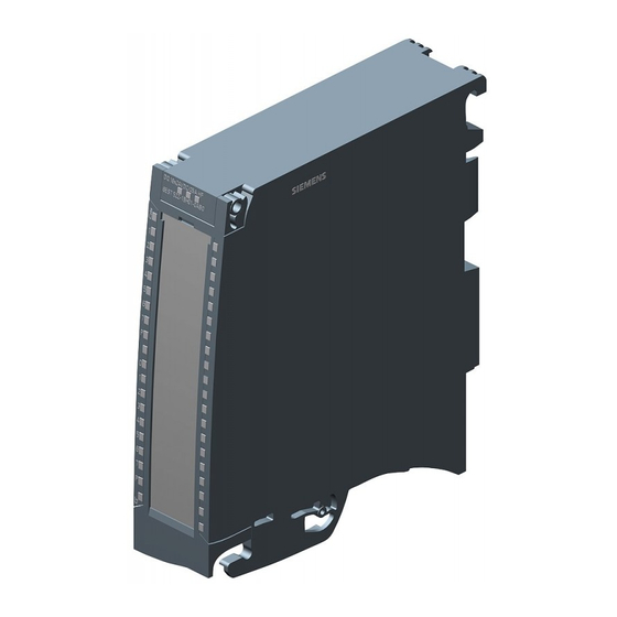
Product overview Properties Article number 6ES7522-1BH01-0AB0 View of the module Figure 2-1 View of the DQ 16x24VDC/0.5A HF module Digital output module DQ 16x24VDC/0.5A HF (6ES7522-1BH01-0AB0) Manual, 06/2018, A5E35683409-AC... - Page 12 (FS) and firmware version (FW) used: Hardware functional status Firmware version Note FS01 V1.0.0 Upgrade to V1.1.0 not possible FS02 V1.1.0 Upgrade and downgrade possible between V1.1.0 and higher Digital output module DQ 16x24VDC/0.5A HF (6ES7522-1BH01-0AB0) Manual, 06/2018, A5E35683409-AC...
- Page 13 Other components The following component can be ordered separately: Front connectors, including potential jumpers and cable ties You can find additional information on accessories in the system manual S7-1500/ET 200MP (https://support.industry.siemens.com/cs/ww/en/view/59191792). Digital output module DQ 16x24VDC/0.5A HF (6ES7522-1BH01-0AB0) Manual, 06/2018, A5E35683409-AC...
-
Page 14: Functions
You configure the switching cycle counter with the following parameters: ● Switching cycle counter enabled/disabled ● Trigger maintenance interrupt when the limit is reached ● Set limit for maintenance interrupt Digital output module DQ 16x24VDC/0.5A HF (6ES7522-1BH01-0AB0) Manual, 06/2018, A5E35683409-AC... - Page 15 Data set DS 131 enables you to overwrite the current counter value for each switching cycle counter. You can set a limit for each switching cycle counter with the "Switching cycle limit" parameter or with data set DS 131. Digital output module DQ 16x24VDC/0.5A HF (6ES7522-1BH01-0AB0) Manual, 06/2018, A5E35683409-AC...
-
Page 16: Wiring
Supply voltage 24 V DC Status display LED (green) Ground ERROR Error display LED (red) Channel or channel status LED POWER supply voltage LED (green) (green/red) Figure 3-1 Block diagram and terminal assignment Digital output module DQ 16x24VDC/0.5A HF (6ES7522-1BH01-0AB0) Manual, 06/2018, A5E35683409-AC... - Page 17 4. Use the terminals 19 and 20 to distribute the potential to the next module. Figure 3-2 Using the potential jumpers Note Ensure that the maximum current load of 8 A per potential jumper is not exceeded. Digital output module DQ 16x24VDC/0.5A HF (6ES7522-1BH01-0AB0) Manual, 06/2018, A5E35683409-AC...
-
Page 18: Parameters/Address Space
(as of V15.0 with HSP0247) Yes/No Channel Switching cycle counter • (as of V15.0 with HSP0247) Yes/No Channel* Channel group Wire break • (CH0 to CH7, CH8 to CH15) Digital output module DQ 16x24VDC/0.5A HF (6ES7522-1BH01-0AB0) Manual, 06/2018, A5E35683409-AC... - Page 19 * If you enable diagnostics for multiple channels, you will receive an alarm surge on failure of the supply voltage because each enabled channel will detect this fault. You can prevent this message burst by assigning the diagnostics function to one channel only. Digital output module DQ 16x24VDC/0.5A HF (6ES7522-1BH01-0AB0) Manual, 06/2018, A5E35683409-AC...
-
Page 20: Description Of Parameters
We recommend that you do not enter this maximum value, but instead set it to 80% or 90%, for example, so that you have enough time to replace the actuator as a preventive measure. Digital output module DQ 16x24VDC/0.5A HF (6ES7522-1BH01-0AB0) Manual, 06/2018, A5E35683409-AC... -
Page 21: Address Space
(e.g. shutdown). This means that even when only one IO controller fails, the other IO controllers associated with the shared device no longer control the assigned submodule of the output module. Digital output module DQ 16x24VDC/0.5A HF (6ES7522-1BH01-0AB0) Manual, 06/2018, A5E35683409-AC... - Page 22 The letters "a to d" are printed onto the module. "QB a" stands for module start address output byte a. Figure 4-1 Address space for configuration as 16-channel DQ 16x24VDC/0.5A HF with value status Digital output module DQ 16x24VDC/0.5A HF (6ES7522-1BH01-0AB0) Manual, 06/2018, A5E35683409-AC...
- Page 23 The addresses for the respective value status of a submodule can also be assigned by the user. Figure 4-2 Address space for configuration as 2 x 8-channel DQ 16x24VDC/0.5A HF S QI with value status Address space for configuration as 1 x 16-channel DQ 16x24VDC/0.5A HF MSO For the configuration as a 1 x 16-channel module (module-internal shared output, MSO), channels 0 to 15 of the module are copied to multiple submodules.
- Page 24 The following figure shows the assignment of the address space for submodules 1 and 2 and the value status. Figure 4-3 Address space for configuration as 1 x 16-channel DQ 16x24VDC/0.5A HF S MSO with value status Digital output module DQ 16x24VDC/0.5A HF (6ES7522-1BH01-0AB0)
- Page 25 The following figure shows the assignment of the address space with submodules 3 and 4 and the value status. Figure 4-4 Address space for configuration as 1 x 16-channel DQ 16x24VDC/0.5A HF S MSO with value status Reference You can find information on the Shared Input/Output (MSI/MSO) function in the section Module-Internal Shared Input/Output (MSI/MSO) of the PROFINET with STEP 7 V13 (https://support.industry.siemens.com/cs/ww/en/view/49948856) function manual.
-
Page 26: Interrupts/Diagnostics Alarms
Interrupts/diagnostics alarms Status and error displays LED displays The following figure shows the LED displays (status and error displays) of module. Figure 5-1 LED displays of the DQ 16x24VDC/0.5A HF module Digital output module DQ 16x24VDC/0.5A HF (6ES7522-1BH01-0AB0) Manual, 06/2018, A5E35683409-AC... - Page 27 Table 5- 3 PWR1 and PWR2 status indication LED PWRx Meaning Solution Supply voltage L+ too low or missing Check the L+ supply voltage. Supply voltage L+ is present and OK Digital output module DQ 16x24VDC/0.5A HF (6ES7522-1BH01-0AB0) Manual, 06/2018, A5E35683409-AC...
-
Page 28: Interrupts
• • Interrupts The digital output module DQ 16x24VDC/0.5A HF supports diagnostic interrupts and maintenance interrupts. You can find detailed information on the event in the error organization block with the "RALRM" instruction (read additional interrupt info) and in the STEP 7 online help. -
Page 29: Diagnostics Alarms
Reset counter with DS131 • * Wire break is also reported for short-circuit of actuator supply to L+. This can lead to inappropriate diagnostics for redun- dant load control. Digital output module DQ 16x24VDC/0.5A HF (6ES7522-1BH01-0AB0) Manual, 06/2018, A5E35683409-AC... -
Page 30: Technical Specifications
Technical specifications Technical specifications of the DQ 16x24VDC/0.5A HF The following table shows the technical specifications as of 06/2018. You will find a data sheet including daily updated technical specifications on the Internet (https://support.industry.siemens.com/cs/ww/en/pv/6ES7522-1BH01-0AB0/td?dl=en). Article number 6ES7522-1BH01-0AB0 General information Product type designation DQ 16x24VDC/0.5A HF... - Page 31 "0" to "1", max. • 500 µs "1" to "0", max. • Parallel switching of two outputs for logic links • for uprating • for redundant control of a load • Digital output module DQ 16x24VDC/0.5A HF (6ES7522-1BH01-0AB0) Manual, 06/2018, A5E35683409-AC...
- Page 32 Yes; Green LED Monitoring of the supply voltage (PWR- • LED) Yes; Green LED Channel status display • Yes; Red LED for channel diagnostics • Yes; Red LED for module diagnostics • Digital output module DQ 16x24VDC/0.5A HF (6ES7522-1BH01-0AB0) Manual, 06/2018, A5E35683409-AC...
- Page 33 Due to the Diagnostics: Wire break function, there is a low level of residual current in the "0" signal state at the output, which may cause the display diodes to flicker. This residual current does not depend on the setting for the wire break diagnostics parameter. Digital output module DQ 16x24VDC/0.5A HF (6ES7522-1BH01-0AB0) Manual, 06/2018, A5E35683409-AC...
- Page 34 S71500 / Distributed I/O System ET 200MP automation system and the ambient temperature. ① Horizontal mounting of the system ② Vertical mounting of the system Figure 6-1 Details on aggregate current of outputs (per group) Digital output module DQ 16x24VDC/0.5A HF (6ES7522-1BH01-0AB0) Manual, 06/2018, A5E35683409-AC...
-
Page 35: Dimensional Drawing
Always observe the specified dimensions for installations in cabinets, control rooms, etc. Figure A-1 Dimension drawing of the DQ 16x24VDC/0.5A HF module Digital output module DQ 16x24VDC/0.5A HF (6ES7522-1BH01-0AB0) Manual, 06/2018, A5E35683409-AC... - Page 36 Dimensional drawing A.1 Dimensional drawing Figure A-2 Dimension drawing of the DQ 16x24VDC/0.5A HF module, side view with open front cover Digital output module DQ 16x24VDC/0.5A HF (6ES7522-1BH01-0AB0) Manual, 06/2018, A5E35683409-AC...
-
Page 37: Parameter Data Records
However, a corresponding error code is written to the STATUS output parameter. The description of the WRREC instruction and the error codes is available in the STEP 7 online help. Digital output module DQ 16x24VDC/0.5A HF (6ES7522-1BH01-0AB0) Manual, 06/2018, A5E35683409-AC... - Page 38 ● Data records 64 to 71 for channels 0 to 7 (submodule 1) ● Data records 64 to 71 for channels 8 to 15 (submodule 2) Address the respective submodule for data record transfer. Digital output module DQ 16x24VDC/0.5A HF (6ES7522-1BH01-0AB0) Manual, 06/2018, A5E35683409-AC...
-
Page 39: Structure Of Parameter Data Sets Ds 64 - 79
1 to 15. The values in byte 0 and byte 1 are fixed and may not be changed. Enable a parameter by setting the corresponding bit to "1". Figure B-1 Structure of data record 64: Bytes 0 to 3 Digital output module DQ 16x24VDC/0.5A HF (6ES7522-1BH01-0AB0) Manual, 06/2018, A5E35683409-AC... -
Page 40: Structure Of Data Set Ds 129
The following figure shows you the structure of data set 129 for 16 channels. Figure B-2 Structure of data set 129: Byte 0 to 63 Digital output module DQ 16x24VDC/0.5A HF (6ES7522-1BH01-0AB0) Manual, 06/2018, A5E35683409-AC... - Page 41 B.3 Structure of data set DS 129 The following figure shows you the structure of data set 129 for 2 submodules with 8 channels each. Figure B-3 Structure of data set 129: Byte 0 to 31 Digital output module DQ 16x24VDC/0.5A HF (6ES7522-1BH01-0AB0) Manual, 06/2018, A5E35683409-AC...
-
Page 42: Structure Of Data Set Ds 130
The following figure shows you the structure of data set 130 for 16 channels. Figure B-4 Structure of data set 130: Byte 0 to 63 Digital output module DQ 16x24VDC/0.5A HF (6ES7522-1BH01-0AB0) Manual, 06/2018, A5E35683409-AC... - Page 43 B.4 Structure of data set DS 130 The following figure shows you the structure of data set 130 for 2 submodules with 8 channels each. Figure B-5 Structure of data set 130: Byte 0 to 31 Digital output module DQ 16x24VDC/0.5A HF (6ES7522-1BH01-0AB0) Manual, 06/2018, A5E35683409-AC...
-
Page 44: Structure Of Data Set Ds 131
The following figure shows you the structure of data set 131. Enable a parameter by setting the corresponding bit to "1". Figure B-6 Structure of data set 131: Bytes 0 to 7 Digital output module DQ 16x24VDC/0.5A HF (6ES7522-1BH01-0AB0) Manual, 06/2018, A5E35683409-AC...