
Related Manuals for Deep Sea Electronics Plc DSE7450


Summary of Contents for Deep Sea Electronics Plc DSE7450
- Page 1 DEEP SEA ELECTRONICS PLC DSE7450 Operator Manual Document Number: 057-170 Author: Ashley Senior DSE7450 Operator Manual ISSUE 2...
- Page 2 The DSE logo is a UK registered trademarks of Deep Sea Electronics PLC. Any reference to trademarked product names used within this publication is owned by their respective companies. Deep Sea Electronics Plc reserves the right to change the contents of this document without prior notice. Amendments List...
-
Page 3: Table Of Contents
DSE7450 Operator Manual TABLE OF CONTENTS Section Page BIBLIOGRAPHY....................7 INSTALLATION INSTRUCTIONS ................... 7 TRAINING GUIDES......................7 MANUALS ........................7 THIRD PARTY DOCUMENTS ..................7 INTRODUCTION ....................8 SPECIFICATIONS .................... 9 SHORT NAMES ......................9 TERMINAL SPECIFICATION ..................9 POWER SUPPLY REQUIREMENTS ................9 3.3.1... - Page 4 DSE7450 Operator Manual 3.13.1 DIMENSIONS ......................29 3.13.2 PANEL CUTOUT ....................29 3.13.3 WEIGHT ......................... 29 3.13.4 FIXING CLIPS ......................30 3.13.5 CABLE TIE FIXING POINTS .................. 31 3.13.6 SILICON SEALING GASKET.................. 31 3.13.7 APPLICABLE STANDARDS ................... 32 3.13.8 ENCLOSURE CLASSIFICATIONS ................. 34 3.13.8.1...
- Page 5 DSE7450 Operator Manual USER CONFIGURABLE INDICATORS ................ 67 OPERATION....................68 CONTROL ........................68 CONTROL PUSH-BUTTONS..................69 STOP MODE ......................... 71 6.3.1 ECU OVERRIDE ....................72 MANUAL MODE ......................73 6.4.1 WAITING IN MANUAL MODE ................73 6.4.2 STARTING SEQUENCE ..................73 6.4.3...
- Page 6 DSE7450 Operator Manual COMMISSIONING ..................108 FAULT FINDING ..................109 11.1 STARTING ......................109 11.2 LOADING ........................ 109 11.3 ALARMS ........................110 11.4 COMMUNICATIONS ....................111 11.5 INSTRUMENTS ....................... 112 11.6 MISCELLANEOUS ....................112 MAINTENANCE, SPARES, REPAIR AND SERVICING ......113 12.1...
-
Page 7: Bibliography
Product manuals are can be downloaded from the DSE website: www.deepseaplc.com DSE PART DESCRIPTION 057-004 Electronic Engines and DSE Wiring 057-169 DSE7450 Configuration PC Software Manual 057-082 DSE2130 Input Expansion Manual 057-083 DSE2157 Output Expansion Manual 057-084 DSE2548 Annunciator Expansion Manual... -
Page 8: Introduction
OEM greater flexibility in the choice of controller to use for a specific application. The DSE7450 controller has been designed to allow the operator to start and stop the generator, manually or automatically via various means to charge a bank of batteries. -
Page 9: Specifications
All modules in the DSE7000 range. DSE7400,DSE74xx All modules in the DSE7400 range. DSE7450 DSE7450 module/controller 3.2 TERMINAL SPECIFICATION NOTE: For purchasing additional connector plugs from DSE, please see the section entitled Maintenance, Spares, Repair and Servicing elsewhere in this document. -
Page 10: Generator And Mains Voltage /Frequency Sensing
Specification 3.4 GENERATOR AND MAINS VOLTAGE /FREQUENCY SENSING Measurement type True RMS conversion Sample Rate 5kHz or better Harmonics Up to 15 or better Input Impedance 300kΩ ph-N Phase to Neutral to 150V AC (absolute maximum) (minimum required for sensing frequency Suitable for 110V nominal (±20% for under/overvoltage detection) Phase to Phase... -
Page 11: Shunt Connection
Specification 3.6.1 SHUNT CONNECTION Take care to ensure the correct polarity of the sensing wires, incorrect orientation will lead to negative current readings. To test the orientation, run the generator and supply load. Ensure all current readings are of correct polarity. 3.6.2 SHUNT ACCURACY Ensure the correct shunts are chosen. -
Page 12: Inputs
Specification 3.7 INPUTS 3.7.1 DIGITAL INPUTS Number 11 configurable inputs Arrangement Contact between terminal and ground Low level threshold 2.1V minimum High level threshold 6.6V maximum Maximum input voltage +50V DC with respect to plant supply negative Minimum input voltage -24V DC with respect to plant supply negative Contact wetting current 4mA typical... -
Page 13: Fuel Level
Specification 3.7.2.3 FUEL LEVEL Can be configured as a flexible sensor. Resistance measurement by measuring voltage across sensor with a Measurement type fixed current applied Arrangement Differential resistance measurement input Measurement current 10mA Full scale 480Ω Over range / fail 540Ω... -
Page 14: Charge Fail Input
Specification 3.7.3 CHARGE FAIL INPUT Minimum voltage Maximum voltage 35V (plant supply) Resolution 0.2V Accuracy ± 1% of max measured voltage Excitation Active circuit constant power output Output Power 2.5W Nominal @12V and 24V Current at 12V 210mA Current at 24V 105mA The charge fail input is actually a combined input and output. -
Page 15: Outputs
NOTE: Output voltage produced is dependant upon module configuration, contact the generator supplier for more information. NOTE: Connection for an AVR is only available on DSE7450 version 2 and onwards. Output Range 0 V DC to 10 V DC floating. -
Page 16: Communication Ports
Specification 3.8 COMMUNICATION PORTS USB Port USB2.0 Device for connection to PC running DSE configuration suite only Max distance 6m (yards) Serial Communication RS232 and RS485 are both fitted but and provide independent operation RS232 Serial port Non – Isolated port Max Baud rate 115K baud subject to S/W TX, RX, RTS, CTS, DSR, DTR, DCD Male 9 way D type connector... -
Page 17: Usb Connection
PC Configuration interface lead (USB type A – type B) DSE Part No 016-125 NOTE: The DC supply must be connected to the module for configuration by PC. NOTE: Refer to DSE7450 PC Configuration Suite Manual (DSE part 057-169) for further details on configuring, monitoring and control. 3.9.3 USB HOST-MASTER (USB DRIVE CONNECTION) USB Type A connection for USB Host facility for USB storage device for data recording. -
Page 18: Rs232
Specification 3.9.4 RS232 The RS232 port on the controller supports the Modbus RTU protocol. The Gencomm register table for the controller is available upon request from the DSE Technical Support Department. RS232 is for short distance communication (max 15m) and is typically used to connect the controller to a telephone or GSM modem for more remote communications. -
Page 19: Recommended External Modems
Specification 3.9.4.2 RECOMMENDED EXTERNAL MODEMS: Multitech Global Modem – MultiModem ZBA (PSTN) • DSE Part Number 020-252 (Contact DSE Sales for details of localisation kits for these modems) Sierra Fastrak Xtend GSM modem kit (PSU, Antenna and modem)* • DSE Part number 0830-001-01 NOTE: For GSM modems a SIM card is required, supplied by your GSM network provider For SMS only, a ‘normal’... -
Page 20: Rs485
Specification 3.9.5 RS485 The RS485 port on the series controller supports the Modbus RTU protocol. The DSE Gencomm register table for the controller is available upon request from the DSE Technical Support Department. RS485 is used for point-to-point cable connection of more than one device (maximum 32 devices) and allows for connection to PCs, PLCs and Building Management Systems (to name just a few devices). -
Page 21: Ethernet
Specification 3.9.6 ETHERNET The Ethernet port on the series controller supports the Modbus TCP protocol. The DSE Gencomm register table for the controller is available upon request from the DSE Technical Support Department. Ethernet is used for point-to-point cable connection of more than one device and allows for connection to PCs, PLCs and Building Management Systems (to name just a few devices). -
Page 22: Direct Pc Connection
Specification 3.9.6.1 DIRECT PC CONNECTION Requirements Crossover Ethernet cable (see Below) • PC with Ethernet port • Crossover network cable Crossover cable wiring detail For the advanced Engineer, a crossover Two pairs crossed, two pairs uncrossed cable is a CAT5 cable with one end 10baseT/100baseTX crossover terminated as T568A... -
Page 23: Connection To Basic Ethernet
Specification 3.9.6.2 CONNECTION TO BASIC ETHERNET Requirements Ethernet cable (see below) • Working Ethernet (company or home network) • PC with Ethernet port • Ethernet cable Ethernet router or ADSL router For the advanced Engineer, this cable has both ends terminated as T568A Ethernet cable wiring detail or T568B. -
Page 24: Connection To Company Infrastructure Ethernet
Specification 3.9.6.3 CONNECTION TO COMPANY INFRASTRUCTURE ETHERNET Requirements Ethernet cable (see below) • Working Ethernet (company or home network) • PC with Ethernet port • Ethernet router PC Network or ADSL router wall connection sockets Ethernet cable For the advanced Engineer, this cable has both ends terminated as T568A... -
Page 25: Connection To The Internet
Specification 3.9.6.4 CONNECTION TO THE INTERNET Requirements Ethernet cable (see below) • Working Ethernet (company or home network) • Working Internet connection (ADSL or DSL recommended) • DSL or ADSL router INTERNET Ethernet cable The DSL/ADSL router will route external network traffic. -
Page 26: Firewall Configuration For Internet Access
Result : Traffic arriving from the WAN (internet) on port xxx is automatically sent to IP address set within the configuration software on the LAN for handling. NOTE: Refer to DSE7450 PC Configuration Suite Manual (DSE part 057-169) for further details on configuring, monitoring and control. -
Page 27: Dsenet® For Expansion Modules
‘first’ unit on the DSENet®. A termination resistor MUST be fitted to the ‘last’ unit on the DSENet®. For connection details, you are referred to the section entitled ‘typical wiring diagram’ elsewhere in this document. NOTE: The DSE7450 module does not support the DSE2510/2520 remote display modules. 3.10.1 DSENET®... -
Page 28: Sounder
Specification 3.11 SOUNDER The module features an internal sounder to draw attention to warning, shutdown and electrical trip alarms. Sounder level 64db @ 1m 3.11.1 ADDING AN EXTERNAL SOUNDER TO THE APPLICATION Should an external alarm or indicator be required, this can be achieved by using the DSE Configuration Suite PC software to configure an auxiliary output for “Audible Alarm”, and by configuring an auxiliary input for “Alarm Mute”... -
Page 29: Dimensions And Mounting
Specification 3.13 DIMENSIONS AND MOUNTING 3.13.1 DIMENSIONS 240.0mm x 181.1mm x 41.7mm (9.4” x 7.1” x 1.6”) 3.13.2 PANEL CUTOUT 220mm x 160mm (8.7” x 6.3”) 3.13.3 WEIGHT 0.7kg (1.4lb) -
Page 30: Fixing Clips
Specification 3.13.4 FIXING CLIPS The module is held into the panel fascia using the supplied fixing clips. Withdraw the fixing clip screw (turn anticlockwise) until only the pointed end is protruding • from the clip. • Insert the three ‘prongs’ of the fixing clip into the slots in the side of the module case. Pull the fixing clip backwards (towards the back of the module) ensuring all three prongs of •... -
Page 31: Cable Tie Fixing Points
Specification 3.13.5 CABLE TIE FIXING POINTS Integral cable tie fixing points are included on the rear of the module’s case to aid wiring. This additionally provides strain relief to the cable loom by removing the weight of the loom from the screw connectors, thus reducing the chance of future connection failures. -
Page 32: Applicable Standards
Specification 3.13.7 APPLICABLE STANDARDS This document conforms to BS4884-1 1992 Specification for presentation BS 4884-1 of essential information. BS 4884-2 This document conforms to BS4884-2 1993 Guide to content BS 4884-3 This document conforms to BS4884-3 1993 Guide to presentation BS EN 60068-2-1 (Minimum -30°C (-22°F) - Page 33 Specification IEEE C37.2 Continued (Standard Electrical Power System Device 50 – Instantaneous overcurrent relay 52 – AC circuit breaker Function Numbers and 53 – Exciter or DC generator relay Contact Designations) 54 – Turning gear engaging device 59AC – AC overvoltage relay 59DC –...
-
Page 34: Enclosure Classifications
Specification ENCLOSURE CLASSIFICATIONS 3.13.8 IP CLASSIFICATIONS 3.13.8.1 The modules specification under BS EN 60529 Degrees of protection provided by enclosures IP65 (Front of module when module is installed into the control panel with the optional sealing gasket). IP42 (front of module when module is installed into the control panel WITHOUT being sealed to the panel) First Digit Second Digit Protection against contact and ingress of solid objects... -
Page 35: Nema Classifications
Specification 3.13.8.2 NEMA CLASSIFICATIONS THE MODULES NEMA RATING (APPROXIMATE) 12 (Front of module when module is installed into the control panel with the optional sealing gasket). 2 (front of module when module is installed into the control panel WITHOUT being sealed to the panel) NOTE: There is no direct equivalence between IP / NEMA ratings. -
Page 36: Installation
Installation 4 INSTALLATION The module is designed to be mounted on the panel fascia. For dimension and mounting details, see the section entitled Specification, Dimension and mounting elsewhere in this document. 4.1 TERMINAL DESCRIPTION To aid user connection, icons are used on the rear of the module to help identify terminal functions. An example of this is shown below. -
Page 37: Dc Supply, Fuel And Start Outputs, Outputs E-J
NOTE: When the module is configured for operation with an electronic engine, FUEL and START output requirements may be different. Refer to Electronic Engines and DSE Wiring for further information. Part No. 057-004. NOTE: Refer to DSE7450 PC Configuration Suite Manual (DSE part 057-169) for further details on configuring, monitoring and control. -
Page 38: Analogue Sensor
NOTE: Refer to DSE7450 PC Configuration Suite Manual (DSE part 057-169) for further details on configuring, monitoring and control. -
Page 39: Magnetic Pickup, Can And Expansion
AWG 20 NOTE: Terminals 31 to 36 are not fitted to the controller. NOTE: AVR terminals 37 & 38 are only fitted to DSE7450 version 2 and onwards. NOTE: Screened cable must be used for connecting the Magnetic Pickup, ensuring that the screen is earthed at one end ONLY. -
Page 40: Load Switching And V1 Generator Ac Voltage Sensing
Connect to generator Neutral terminal (AC) AWG 18 NOTE: Refer to DSE7450 PC Configuration Suite Manual (DSE part 057-169) for further details on configuring, monitoring and control. NOTE: The above table describes connections to a three phase, four wire alternator. For alternative wiring topologies, please see the ALTERNATIVE AC TOPOLOGIES section of this manual. -
Page 41: Generator Dc Voltage & Current Sensing
Installation 4.1.6 GENERATOR DC VOLTAGE & CURRENT SENSING DESCRIPTION CABLE NOTES SIZE Battery Plant Supply Input 1.0mm² Connect to battery plant supply positive Positive AWG 18 (Recommend 2A fuse) Battery Plant Supply Input 1.0mm² Connect to battery plant supply negative Negative AWG 18 1.0mm²... -
Page 42: Configurable Digital Inputs
Switch to negative AWG 20 0.5mm² Configurable Digital Input J Switch to negative AWG 20 NOTE: Refer to DSE7450 PC Configuration Suite Manual (DSE part 057-169) for further details on configuring, monitoring and control. 4.1.8 PC CONFIGURATION INTERFACE CONNECTOR Cable Description... -
Page 43: Rs232 Connector
Installation 4.1.9 RS232 CONNECTOR PIN No Notes Received Line Signal Detector (Data Carrier Detect) Received Data Transmit Data Data Terminal Ready Signal Ground Data Set Ready Request To Send Clear To Send Ring Indicator View looking into the male connector on the module 4.1.10 RS485 CONNECTOR PIN No... -
Page 44: Typical Wiring Diagram
Installation 4.2 TYPICAL WIRING DIAGRAM As every system has different requirements, these diagrams show only a TYPICAL system and do not intend to show a complete system. Genset manufacturers and panel builders may use these diagrams as a starting point; however, you are referred to the completed system diagram provided by your system manufacturer for complete wiring detail. -
Page 45: Typical Single Line Diagrams
Installation 4.3 TYPICAL SINGLE LINE DIAGRAMS 4.3.1 WITH MAINS SENSING 4.3.1.1 AC GENERATOR AND RECTIFIER WITH A COMMON DC BUS... -
Page 46: Ac Generator And Rectifier With A Common Ac & Dc Bus
Installation 4.3.1.2 AC GENERATOR AND RECTIFIER WITH A COMMON AC & DC BUS... -
Page 47: Dc Generator With A Common Dc Bus
Installation 4.3.1.3 DC GENERATOR WITH A COMMON DC BUS NOTE: Generator AC sensing is required to be disabled for this application. Refer to DSE7450 PC Configuration Suite Manual (DSE part 057-169) for further details on configuring, monitoring and control. -
Page 48: Without Mains Sensing
Installation 4.3.2 WITHOUT MAINS SENSING 4.3.2.1 AC GENERATOR WITH EXTERNAL RECTIFIER NOTE: Mains sensing is required to be disabled for this application. Refer to DSE7450 PC Configuration Suite Manual (DSE part 057-169) for further details on configuring, monitoring and control. -
Page 49: Dc Generator
Installation 4.3.2.2 DC GENERATOR NOTE: Mains and Generator AC sensing is required to be disabled for this application. Refer to DSE7450 PC Configuration Suite Manual (DSE part 057-169) for further details on configuring, monitoring and control. -
Page 50: Earth Systems
Installation 4.4 EARTH SYSTEMS 4.4.1 NEGATIVE EARTH The typical wiring diagrams located within this document show connections for a negative earth system (the battery negative connects to Earth) 4.4.2 POSITIVE EARTH When using a DSE module with a Positive Earth System (the battery positive connects to Earth), the following points must be followed: Follow the typical wiring diagram as normal for all sections EXCEPT the earth points •... -
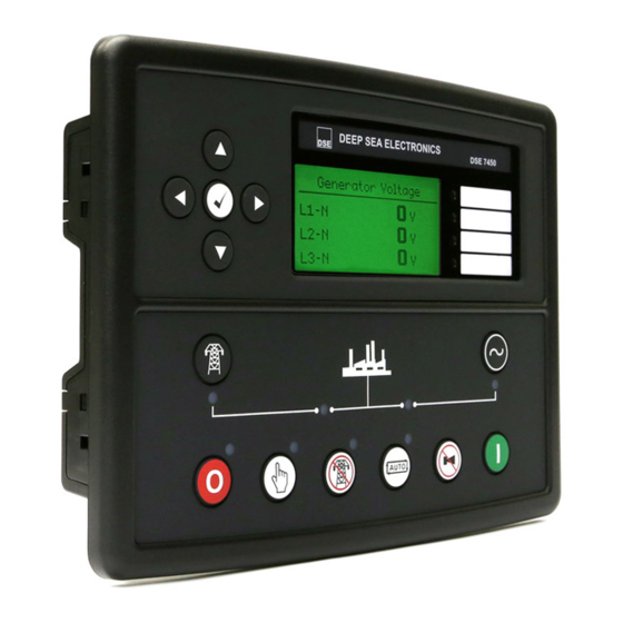
Page 51: Description Of Controls
Description Of Controls 5 DESCRIPTION OF CONTROLS Main status and Four configurable instrumentation display Menu navigation LEDs buttons Transfer to Generator Transfer to Mains (manual mode only) (manual mode only) Start engine (when in Manual Select Stop or Test mode) mode Select Manual Select Test... -
Page 52: Quickstart Guide
Description Of Controls 5.1 QUICKSTART GUIDE This section provides a quick start guide to the module’s operation. 5.1.1 STARTING THE ENGINE First, select manual mode then press the Start button to crank the engine. NOTE: For further details, see the section entitled ‘OPERATION’ elsewhere in this manual. 5.1.2 STOPPING THE ENGINE Select Stop/Reset... -
Page 53: Viewing The Instrument
Description Of Controls 5.2 VIEWING THE INSTRUMENT PAGES It is possible to scroll to display the different pages of information by repeatedly operating the next / previous page buttons If you want to view one of the instrument pages towards the end of the list, it may be quicker to scroll left through the pages rather than right! -
Page 54: Status
Description Of Controls 5.2.1 STATUS This is the ‘home’ page, the page that is displayed when no other page has been selected, and the page that is automatically displayed after a period of inactivity (LCD Page Timer) of the module control buttons. -
Page 55: Engine
Description Of Controls 5.2.2 ENGINE Contains instrumentation gathered about the engine itself, some of which may be obtained using the CAN or other electronic engine link. Engine Speed • Oil Pressure • Coolant Temperature • Engine Battery Volts • Engine Run Time •... -
Page 56: Generator
Description Of Controls 5.2.3 GENERATOR Contains electrical values of the generator AC alternator, measured from the module’s AC voltage inputs. Generator Voltage (ph-N) • • Generator Voltage (ph-ph) Generator Frequency • Generator Phase Sequence • Generator Active Config • AVR Bias Voltage •... -
Page 57: Event Log
Description Of Controls 5.2.7 EVENT LOG The module maintains a log of past alarms and/or selected status changes. The log size has been increased in the module over past module updates and is always subject to change. At the time of writing, the modules log is capable of storing the last 250 log entries. Under default factory settings, the event log only includes shutdown and electrical trip alarms logged (The event log does not contain Warning alarms);... -
Page 58: Alarms
Description Of Controls 5.2.8 ALARMS When an alarm is present, the Audible Alarm will sound and the Common alarm LED if configured will illuminate. The audible alarm can be silenced by pressing the Mute button The LCD display will jump from the ‘Information page’ to display the Alarm Page Number of present alarms. -
Page 59: Serial Port
Description Of Controls 5.2.9 SERIAL PORT 5.2.9.1 RS232 SERIAL PORT This section is included to give information about the RS232 serial port and external modem (if connected). The items displayed on this page will change depending upon configuration of the module. You are referred to your system supplier for further details. - Page 60 Description Of Controls Example 1 continued – Modem diagnostics Modem diagnostic screens are included; press when viewing the RS232 Serial Port instrument to cycle the available screens. If you are experiencing modem communication problems, this information will aid troubleshooting. Shows the state of the modem communication lines. These can Serial Port help diagnose connection problems.
- Page 61 Description Of Controls Modem Setup Sequence If the Modem and module communicate successfully: In case of communication failure between the modem and module, the modem is automatically reset and initialisation is attempted once more: In the case of a module that is unable to communicate with the modem, the display will continuously cycle between ‘Modem Reset’...
- Page 62 Description Of Controls Example 2 – Module connected to a modem. Example 3 – Modem status of a GSM modem Currently connected GSM operator and signal strength. Many GSM modems are fitted with a status LED to show operator cell status and ringing indicator. These can be a useful troubleshooting tool.
-
Page 63: Rs485 Serial Port
Description Of Controls 5.2.9.2 RS485 SERIAL PORT This section is included to give information about the currently selected serial port and external modem (if connected). The items displayed on this page will change depending upon configuration of the module. You are referred to your system supplier for further details. -
Page 64: About
Description Of Controls 5.2.10 ABOUT 5.2.10.1 MODULE INFORMATION Contains important information about the module and the firmware versions. This information may be asked for when contacting DSE Technical Support Department for advice. Variant (7410 or 7420) • About Application Version – The version of the module’s main •... -
Page 65: Ethernet
Description Of Controls 5.2.10.2 ETHERNET PAGES Whilst in the ‘ABOUT’ section, press to access more information about the network settings. Network settings change be configured using DSE Configuration Suite Software. The module must be rebooted for the changes to take effect. Network IP Address –... -
Page 66: Data Logging
Description Of Controls 5.2.10.3 DATA LOGGING PAGES Whilst in the ‘ABOUT’ section, press to access more information about the data logging settings. Location of stored data. Data Logging Internal module memory or external Log to internal memory USB memory. Logging active No USB drive present If data logging is active or inactive Inserting a USB drive to the host USB will display the following change to the page. -
Page 67: User Configurable Indicators
Description Of Controls 5.3 USER CONFIGURABLE INDICATORS These LEDs can be configured by the user to indicate any one of 100+ different functions based around the following:- • Indications - Monitoring of a digital input and indicating associated functioning user’s equipment - Such as Battery Charger On or Louvres Open, etc. -
Page 68: Operation
Operation 6 OPERATION 6.1 CONTROL Control of the module is via push buttons mounted on the front of the module with STOP/RESET, MANUAL, TEST, AUTO, ALARM MUTE and START functions. For normal operation, these are the only controls which need to be operated. The smaller push buttons are used to access further information such as mains voltage or to change the state of the load switching devices when in manual mode. -
Page 69: Control Push-Buttons
Operation 6.2 CONTROL PUSH-BUTTONS Stop / Reset This button places the module into its Stop/Reset mode. This will clear any alarm conditions for which the triggering criteria have been removed. If the engine is running and the module is in Stop mode, the module will automatically instruct the changeover device to unload the generator (‘Close Generator’... - Page 70 Operation Transfer to Generator Operative in Manual Mode only ‘Normal’ breaker button control Allows the operator to transfer the load to the generator • ‘Alternative’ breaker button control If mains is on load, transfers the load to the generator. • If generator is on load, opens the generator breaker •...
-
Page 71: Stop Mode
Operation 6.3 STOP MODE NOTE: If a digital input configured to panel lock is active, changing module modes will not be possible. Viewing the instruments and event logs is NOT affected by panel lock. STOP mode is activated by pressing the button. -
Page 72: Ecu Override
Operation 6.3.1 ECU OVERRIDE NOTE: ECU Override function is only applicable when the controller is configured for a CAN engine. NOTE: Depending upon system design, the ECU may be powered or unpowered when the module is in STOP mode. ECU override is only applicable if the ECU is unpowered when in STOP mode. -
Page 73: Manual Mode
Operation 6.4 MANUAL MODE NOTE: If a digital input configured to panel lock is active, changing module modes will not be possible. Viewing the instruments and event logs is NOT affected by panel lock. Activate Manual mode be pressing the pushbutton. -
Page 74: Engine Running
Operation 6.4.3 ENGINE RUNNING In manual mode, the load is not transferred to the generator unless a ‘loading request’ is made. A loading request can come from a number of sources. Pressing the transfer to generator button • Mains supply out of limits •... -
Page 75: Test Mode
Operation 6.5 TEST MODE NOTE: If a digital input configured to panel lock is active, changing module modes will not be possible. Viewing the instruments and event logs is NOT affected by panel lock. Activate test mode be pressing the pushbutton. -
Page 76: Engine Running
Operation 6.5.3 ENGINE RUNNING Once the engine is running, the Warm Up timer, if selected, begins, allowing the engine to stabilise before accepting the load. Load will be automatically transferred from the mains supply to the generator. NOTE: The load transfer signal remains inactive until the Oil Pressure has risen. This prevents excessive wear on the engine. -
Page 77: Automatic Mode
Operation 6.6 AUTOMATIC MODE NOTE: If a digital input configured to panel lock is active, changing module modes will not be possible. Viewing the instruments and event logs is NOT affected by panel lock. Activate auto mode be pressing the pushbutton. -
Page 78: Engine Running
Operation Additionally, rising oil pressure can be used to disconnect the starter motor (but cannot detect underspeed or overspeed). NOTE: If the unit has been configured for CAN, speed sensing is via CAN. After the starter motor has disengaged, the Safety On timer activates, allowing Oil Pressure, High Engine Temperature, Under-speed, Charge Fail and any delayed Auxiliary fault inputs to stabilise without triggering the fault. -
Page 79: Plant Battery Charging Scheme
Operation 6.7 PLANT BATTERY CHARGING SCHEME 6.7.1 START REQUEST Starting requests can be from the following sources: The Plant Battery discharges below the level of the Depth of Discharge (DOD) setting • The DC voltage falls beneath the low Plant Battery Voltage alarm level •... -
Page 80: Calculating Effective Battery Capacity
Operation 6.7.3 CALCULATING EFFECTIVE BATTERY CAPACITY The effective battery capacity is calculated whilst the battery is charging upon a fixed formula: It = C (C / IH) Where: C is the rated capacity (amp hours) of the Plant Batteries combined IH is the charge rate (amps per hour) It is the effective battery capacity K is Peukert's Constant (obtained from the battery data sheet or when the battery is calibrated) or by the calculated Peukert’s... -
Page 81: Determining The Charge Mode
Operation 6.7.5 DETERMINING THE CHARGE MODE 6.7.5.1 TWO STAGE CHARGER NOTE: When using a two stage charger, the Minimum Float Voltage Level must be set higher than the float voltage produced by the charging device as shown below. Charging State Floating State Float Charge Timer Bulk Stage... -
Page 82: Three Stage Charger
Operation 6.7.5.2 THREE STAGE CHARGER Charging State Floating State Float Charge Timer Bulk Absorption Stage Float Stage Stage Plant Battery Voltage f = Minimum Float Voltage Level Plant Battery Current c = Charge Rate Current The charge modes for a three stage charger are determined as follows: Charge Status Description Discharged... -
Page 83: Four Stage Charger
Operation 6.7.5.3 FOUR STAGE CHARGER NOTE: When using a four stage charger, the charging device must be permanently powered for the storage charge to occur. Charging State Charging State Floating State (Storage Stage) Floating State Float Charge Float Charge Timer Timer Bulk Bulk... -
Page 84: Protections
Protections 7 PROTECTIONS When an alarm is present, the Audible Alarm will sound and the Common alarm LED if configured will illuminate. The audible alarm can be silenced by pressing the Mute button The LCD display will jump from the ‘Information page’ to display the Alarm Page Number of present alarms. -
Page 85: Protections Disabled
Protections 7.2 PROTECTIONS DISABLED User configuration is possible to prevent Shutdown / Electrical Trip alarms from stopping the engine. Under such conditions, Protections Disabled will appear on the module display to inform the operator of this status. This feature is provided to assist the system designer in meeting specifications for “Warning only”, “Protections Disabled”, “Run to Destruction”, “War mode”... -
Page 86: Indications
Protections 7.3 INDICATIONS Indications are non-critical and often status conditions. They do not appear on the LCD of the module as a text message. However, an output or LED indicator can be configured to draw the operator’s attention to the event. Example Input configured for •... -
Page 87: Warnings
Protections 7.4 WARNINGS Warnings are non-critical alarm conditions and do not affect the operation of the generator system, they serve to draw the operators attention to an undesirable condition. Example Alarm Low Oil Pressure Warning In the event of an alarm the LCD will jump to the alarms page, and scroll through all active warnings and shutdowns. - Page 88 Protections Display Reason If a flexible sensor has been configured to a digital input Flexible Sender 1,2 & 3 Digital Input and has been configured as a warning the appropriate LCD message will be displayed. The module detects that the value of the sensor has Flexible Sender 1,2 &...
- Page 89 Protections Display Reason The module detects that the plant battery temperature has Plant Battery High Temperature exceeded the high plant battery temperature pre-alarm setting. The module detects that the plant battery temperature has Plant Battery Low Temperature fallen below the high plant battery temperature pre-alarm setting.
-
Page 90: Electrical Trips
Protections 7.5 ELECTRICAL TRIPS NOTE: Shutdown and Electrical Trip alarms can be disabled by user configuration. See the section entitled Protections Disabled elsewhere in this document. Electrical trips are latching and stop the Generator but in a controlled manner. On initiation of the electrical trip condition the module will de-energise the ‘Close Generator’... - Page 91 Protections Display Reason If a flexible sensor has been configured to a digital Flexible Sender 1,2 & 3 Digital Input input and has been configured as an electrical trip, the appropriate LCD message will be displayed. The module detects that the value of the sensor has Flexible Sender 1,2 &...
-
Page 92: Shutdowns
Protections 7.6 SHUTDOWNS NOTE: Shutdown and Electrical Trip alarms can be disabled by user configuration. See the section entitled Protections Disabled elsewhere in this document. Shutdowns are latching alarms and stop the Generator. Clear the alarm and remove the fault then press Stop/Reset to reset the module. - Page 93 Protections Display Reason The module detects that the engine ECU has detected that ECU After Treatment the after treatment is currently in progress. The module detects that the engine ECU has detected a ECU Amber fault causing an Amber alarm. The module detects that the engine ECU has detected a ECU Protect fault causing a Protect alarm.
- Page 94 Protections Display Reason The module detects that the Load Current has exceeded Load Over Current the trip level. The level detected by the fuel level sensor is below the Low Fuel Level low fuel level setting. The module detects that the engine oil pressure has Low Oil Pressure fallen below the low oil pressure alarm trip setting level after the Safety On timer has expired.
-
Page 95: Dc Overcurrent Warning/ Electrical Trip/Shutdown Alarm
Protections 7.7 DC OVERCURRENT WARNING/ ELECTRICAL TRIP/SHUTDOWN ALARM The overcurrent alarm combines a simple warning trip level with a fully functioning IDMT curve for thermal protection. 7.7.1 IMMEDIATE WARNING If the Immediate Warning is enabled, the controller generates a warning alarm as soon as the Trip level is reached. - Page 96 Protections Factory settings for the IDMT Alarm are as follows (screen capture from the DSE Configuration Suite PC software): (Trip setting value) (time multiplier) These settings provide for normal running of the generator up to full load. If full load is surpassed, the Immediate Warning alarm is triggered, the set continues to run.
- Page 97 Protections...
-
Page 98: Dc Short Circuit Alarm
Protections 7.8 DC SHORT CIRCUIT ALARM If the Short Circuit alarm is enabled, the controller begins following the IDMT ‘curve’. If the Trip is surpassed for an excess amount of time the Alarm triggers (Shutdown or Electrical trip as selected in Action). -
Page 99: Maintenance Alarm
Protections 7.9 MAINTENANCE ALARM Depending upon module configuration one or more levels of engine or plant battery maintenance alarm may occur based upon a configurable schedule. Example 1 Screen capture from DSE Configuration Suite Software showing the configuration of Plant Battery Maintenance Alarm 1 and Maintenance Alarm 2. -
Page 100: Scheduler
Scheduler 8 SCHEDULER The controller contains an inbuilt exercise run scheduler, capable of automatically starting and stopping the set. Up to 16 scheduled start/stop sequences can be configured to repeat on a 7-day or 28-day cycle. Scheduled runs may be on load or off load depending upon module configuration. Example Screen capture from DSE Configuration Suite Software showing the configuration... -
Page 101: Front Panel Configuration
Front Panel Configuration 9 FRONT PANEL CONFIGURATION This configuration mode allows the operator limited customising of the way the module operates. Use the module’s navigation buttons to traverse the menu and make value changes to the parameters: Increase value / next item Previous page Decrease value / next item... -
Page 102: Accessing The Main Front Panel Configuration Editor
Front Panel Configuration 9.1 ACCESSING THE MAIN FRONT PANEL CONFIGURATION EDITOR Ensure the engine is at rest and the module is in STOP mode by pressing the Stop/Reset button. Press the Stop/Reset and Info buttons simultaneously. If a module security PIN has been set, the PIN number request is then shown : Press , the first ‘#’... -
Page 103: Editing A Parameter
NOTE: The PIN number is automatically reset when the editor is exited (manually or automatically) to ensure security. NOTE: More comprehensive module configuration is possible via PC configuration software. Refer to DSE7450 PC Configuration Suite Manual (DSE part 057-169) for further details on configuring, monitoring and control. -
Page 104: Adjustable Parameters
Front Panel Configuration 9.2 ADJUSTABLE PARAMETERS Front Panel Configuration Editor. For descriptions of the parameters, you are referred to The DSE series Configuration Suite Manual, DSE Part 057-160. Section Parameter As Shown On Display Values Display Contrast Language English Current Date and Time hh:mm Oil Pressure Low shutdown 0.00 bar 0 psi 0 kPa... - Page 105 Front Panel Configuration Section Parameter As Shown On Display Values AVR Tgt 0.00V Generator Under Voltage Shutdown Under Voltage Pre-Alarm Nominal Voltage Over Voltage Pre-Alarm Over Voltage Shutdown Under Frequency Shutdown Under Frequency Pre-Alarm Nominal Frequency Over Frequency Pre-Alarm Over Frequency Shutdown AC System 3 Phase 4 Wire Transient Delay...
- Page 106 Front Panel Configuration Section Parameter As Shown On Display Values Battery Capacity Battery Charge Rate Depth of Discharge Full Charge Level Floating Min Voltage 0.0V Peukert’s Constant 1.00 Plant Battery Low Temperature Shutdown Inactive/Active Plant Battery Low Temperature Shutdown 0ºC 0ºF Plant Battery Low Temperature Warning Inactive/Active Plant Battery Low Temperature Warning (If Active)
-
Page 107: Accessing The 'Running' Configuration Editor
Front Panel Configuration 9.3 ACCESSING THE ‘RUNNING’ CONFIGURATION EDITOR The ‘running’ editor can be entered while the engine is running. All protections remain active if the engine is running while the running editor is entered. Press and hold the button to enter the running editor. 9.3.1 EDITING A PARAMETER Enter the editor as described above. -
Page 108: Commissioning
Commissioning 10 COMMISSIONING Before the system is started, it is recommended that the following checks are made:- The unit is adequately cooled and all the wiring to the module is of a standard and rating • compatible with the system. Check all mechanical parts are fitted correctly and that all electrical connections (including earths) are sound. -
Page 109: Fault Finding
Fault Finding 11 FAULT FINDING 11.1 STARTING Symptom Possible Remedy Unit is inoperative Check the battery and wiring to the unit. Check the DC supply. Check the DC fuse. Read/Write configuration does not operate Unit shuts down Check DC supply voltage is not above 35 Volts or below 9 Volts Check the operating temperature is not above 70°C. -
Page 110: Alarms
Fault Finding 11.3 ALARMS Symptom Possible Remedy Unit locks out on Emergency If no Emergency Stop Switch is fitted, ensure that a DC positive Stop signal is connected to the Emergency Stop input. Check emergency stop switch is functioning correctly. Check Wiring is not open circuit. Intermittent Magnetic Pick-up Ensure that Magnetic pick-up screen only connects to earth at one sensor fault... -
Page 111: Communications
Fault Finding 11.4 COMMUNICATIONS Symptom Possible Remedy CAN DATA FAIL Indicates failure of the CAN data link to the engine ECU. Check all wiring and termination resistors (if required). Check the ECU OVERRIDE function detailed in the section entitled OPERATION elsewhere in this manual. RS485 inoperative Check : Connection cable –... -
Page 112: Instruments
Fault Finding 11.5 INSTRUMENTS Symptom Possible Remedy Inaccurate generator Check that the shunt settings are correct for the application. measurements on controller display Check that the shunts are wired correctly with regards to the direction of current flow and additionally ensure that shunts are connected in the correct. -
Page 113: Maintenance, Spares, Repair And Servicing
Maintenance, Spares, Repairs and Servicing 12 MAINTENANCE, SPARES, REPAIR AND SERVICING The controller is Fit and Forget. As such, there are no user serviceable parts within the controller. In the case of malfunction, you should contact your original equipment manufacturer (OEM). 12.1 PURCHASING ADDITIONAL CONNECTOR PLUGS FROM DSE If you require additional plugs from DSE, please contact our Sales department using the part numbers below. -
Page 114: Dsenet Expansion Modules
Maintenance, Spares, Repairs and Servicing 12.4 DSENET EXPANSION MODULES NOTE: A maximum of twenty (20) expansion modules can be connected to the DSENet®. NOTE: DSENet® utilises an RS485 connection. Using Belden 9841 (or equivalent) cable allows for the expansion cable to be extended to a maximum of 1.2km. DSE Stock and supply Belden 9841 cable. -
Page 115: Warranty
Warranty 13 WARRANTY DSE Provides limited warranty to the equipment purchaser at the point of sale. For full details of any applicable warranty, refer to the original equipment supplier (OEM) 14 DISPOSAL 14.1 WEEE (WASTE ELECTRICAL AND ELECTRONIC EQUIPMENT) If you use electrical and electronic equipment you must store, collect, treat, recycle and dispose of WEEE separately from your other waste... - Page 116 This Page is Intentionally Left Blank...
Need help?
Do you have a question about the DSE7450 and is the answer not in the manual?
Questions and answers