Table of Contents
Advertisement
Advertisement
Table of Contents

Related Manuals for Mark-10 ESM303


Summary of Contents for Mark-10 ESM303
- Page 1 ESM303 ESM303H Models & FORCE TEST STANDS User’s Guide...
-
Page 2: Table Of Contents
With proper usage, we are confident that you will get many years of great service with this product. Mark-10 test stands are ruggedly built for many years of service in laboratory and industrial environments. This User’s Guide provides setup, safety, and operation instructions. Dimensions and specifications are also provided. -
Page 3: Overview
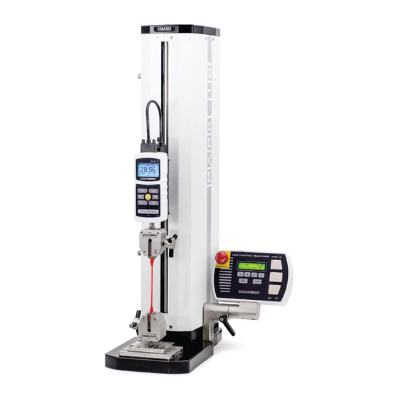
User’s Guide Models ESM303 & ESM303H Test Stands 1 OVERVIEW 1.1 List of included items Description Qty. ESM303 Qty. ESM303H Force gauge mounting adapter Indicator / load cell mounting adapter Force gauge / indicator mounting screws, Indicator mounting screws, #6-32 x 1/2... - Page 4 User’s Guide Models ESM303 & ESM303H Test Stands 1.2 Physical features Note the following physical features. The user’s guide will reference this terminology. 1.2.1 ESM303 Column cap Column Limit switch (upper) Interface cable Crosshead Force gauge Emergency stop Upper grip...
-
Page 5: Setup And Safety
Place the stand on a clean, flat and level work area free from vibration. For the vertically oriented ESM303, It is suggested to mount the stand to a work bench via screws fastened into the underside of the base. Failure to properly mount the test stand may make it more vulnerable to tipping, especially if a column extension is used, causing a hazardous situation. - Page 6 User’s Guide Models ESM303 & ESM303H Test Stands 2. Install the control panel to the mounting bracket utilizing two #8-32 screws. 3. The viewing angle may be adjusted by loosening the lever, positioning the control panel, and re- tightening the lever.
- Page 7 2.4.2 USB driver installation To use this output, install the USB driver provided on the Resource CD, labeled “Mark-10 USB Device”. Installation instructions may also be found on the CD or may be downloaded from www.mark-10.com.
- Page 8 User’s Guide Models ESM303 & ESM303H Test Stands Further instructions for configuring communication parameters may be found in the Test Function Setup section. If PC control is used, a full listing of available ASCII commands may be found in the Operating Modes section.
- Page 9 User’s Guide Models ESM303 & ESM303H Test Stands Install the L-bracket with the same two flat head screws, as shown below: 4. Mount the load cell to the L-bracket utilizing the included hardware, as shown below. 5. Mount the indicator utilizing the four provided thumb screws, and insert the Plug & Test connector into the indicator.
- Page 10 If using a grip or fixture from a supplier other than Mark-10, ensure that it is constructed of suitably rugged materials and components.
-
Page 11: Operation Basics
User’s Guide Models ESM303 & ESM303H Test Stands 4. The test stand should be serviced by a trained technician only. Power must be disconnected before the column covers are removed. After the above safety checks and procedures have been performed, the test stand may be powered on and is ready for operation. - Page 12 Function SOFT KEYS Functions are determined by the corresponding text on the display. UP / RIGHT Commences movement in the up (ESM303) or right (ESM303H) direction. STOP Stops crosshead movement. DOWN / LEFT Commences movement in the down (ESM303) or left (ESM303H) direction.
-
Page 13: Test Function Setup
Password protection Standard All ESM303 test stands are supplied in Demo Mode, as explained in the Overview section. After Demo Mode expires, only installed functions will be displayed in Test Function Setup. To access Test Function Setup menu, press menu from the Operating Mode home screen, which appears as follows: S P E E D : 0 . - Page 14 User’s Guide Models ESM303 & ESM303H Test Stands After pressing menu, the initial Test Function Setup screen appears as follows: S P E E D : 2 0 . 0 0 < − − > E S C E N T R...
- Page 15 User’s Guide Models ESM303 & ESM303H Test Stands U P S P E E D : 1 0 . 7 3 − E S C E N T R Label Description Increments the speed setting. Holding down + will increment at an increasingly faster rate.
- Page 16 User’s Guide Models ESM303 & ESM303H Test Stands Label Description Increases the number of cycles in increments of 1. Holding down + will increment at an increasingly faster rate. If 99999 is reached the next number will be 00000 and continue incrementing.
- Page 17 The ESM303 protects a load cell or force gauge from overload by measuring incoming analog voltage and stopping crosshead travel when the programmed percentage of full scale has been reached. The default setting is for Mark-10 instruments (±1V full scale), however, the setting may be changed to ±2V or ±4V to accommodate other instruments.
- Page 18 User’s Guide Models ESM303 & ESM303H Test Stands 4.6 Preload 4.6.1 Function This setting corresponds to the test stand’s response to an initial load, referred to as a preload. The crosshead can stop and/or zero the travel display when the preload has been reached. This function is useful for applications such as spring testing, elongation testing, and tensile and compression testing of various materials.
- Page 19 User’s Guide Models ESM303 & ESM303H Test Stands Default setting: OFF Available settings: ON, OFF L O A D H O L D I N G : − E S C E N T R Label Description + or –...
- Page 20 Exits the function without saving changes Note: When using an ESM303 / ESM303H test stand with a Series 7 instrument, enable Break Detection in either the test stand or the instrument. The function will not work if simultaneously enabled in both devices.
- Page 21 User’s Guide Models ESM303 & ESM303H Test Stands Label Description + or – Cycles through the available settings ENTR Returns to the Function Setup menu Exits the function without saving changes 4.11 Stop bits and parity (STOP & PAR) This corresponds to the stop bits and parity settings of the computer program controlling the stand.
- Page 22 User’s Guide Models ESM303 & ESM303H Test Stands 4.13 Programmable button function (KEYS) Three button function modes are available: 1. Maintained The crosshead will move continuously once the button has been pressed and held. Subsequently pressing STOP will stop crosshead motion.
- Page 23 User’s Guide Models ESM303 & ESM303H Test Stands 4.15 Profiles 4.15.1 Save a new profile To save a new profile, configure the menu settings as required, then exit the menu. When prompted to save changes, press YES. The display appears as follows:...
- Page 24 User’s Guide Models ESM303 & ESM303H Test Stands 4.16 Default settings Revert to the following factory settings: SPEED: 10 in/min UP / RIGHT SPEED: 10 in/min DOWN / LEFT SPEED: 10 in/min AUTO RETURN: CYCLING: 00000 (off) HI / RIGHT LIMIT: +20.000 in...
-
Page 25: Operating Modes
Models ESM303 & ESM303H Test Stands 5 OPERATING MODES 5.1 Overview The ESM303 can be operated in several modes, including combinations of these modes: 1. FollowMe Mode Crosshead movement responds to pushing or pulling on the force gauge shaft or load cell. - Page 26 User’s Guide Models ESM303 & ESM303H Test Stands 1. Basic & Auto Return Modes (travel indication option not installed): S P E E D : 0 . 0 0 m e n u m i n m a x S E T 2.
- Page 27 User’s Guide Models ESM303 & ESM303H Test Stands S P E E D : 0 . 0 0 F o l l o w M e A c t i v e CAUTION! Exercise extreme caution when handling low capacity force gauges or load cells, as overload can occur.
- Page 28 ESM303H 5.4.3 Overload protection The available interface cable is required for overload protection of a Mark-10 force gauge or load cell. If overload protection is installed and enabled, the crosshead will stop when the programmed percentage of full scale of the instrument has been reached.
- Page 29 User’s Guide Models ESM303 & ESM303H Test Stands When the cycling sequence and the crosshead has stopped at a soft limit, the limit condition may be overridden by pressing and holding either directional button. 5.6.1 Dwell time Dwell time is the amount of time, in seconds, for which the crosshead stops at a limit during a cycle sequence.
- Page 30 User’s Guide Models ESM303 & ESM303H Test Stands must be set to any value in the opposite measuring direction. For example, for a test requiring load holding at 10 lbF of compression force, set the upper set point to 30 lbF tension (as an example), and the lower set point to 10 lbF compression.
-
Page 31: Communication
6 COMMUNICATION 6.1 Setup The ESM303 can transmit force and travel (optional) data to a PC. The following settings are required for proper functioning of all test stand functions and data output: Force gauge / indicator (Series 5 / 7 only):... - Page 32 6.2.1 Force gauge / indicator commands Mark-10 force gauge and indicator commands are compatible with the ESM303. To open this channel of communication, use a forward slash “ / “ (no quotations), followed by the commands, followed by a back slash “...
-
Page 33: Function Activation
E S C E N T R The request code must be supplied to Mark-10 or a distributor, who will then provide a corresponding authorization code to activate the function. The process for entering the authorization code is as follows: 1. - Page 34 5. The door may be opened in the clockwise or counter-clockwise direction. Magnetic detents are provided for the closed position. If the interlock cable is plugged in, the ESM303’s control panel will display the message “SHIELD OPEN” when the door is open. The ESM303 cannot be...
- Page 35 Models ESM303 & ESM303H Test Stands 9 AF009 TRAVEL INDICATION OPTION RETROFIT Retrofitting an ESM303 test stand with the AF009 travel indication option requires hardware installation and entering an activation code. The instructions below reference Model ESM303, however, the process is similar with the ESM303H.
- Page 36 User’s Guide Models ESM303 & ESM303H Test Stands Electronics support plate 4. Carefully tilt the plate back slightly, then disconnect the 3 connectors, as identified in the images below. Then, remove the plate. 5. Note the components below. Then attach the encoder strip to the plate with 7 screws.
- Page 37 The column may be separated from the base to accommodate alternative mounting arrangements, for considerations such as safety, increased sample clearance, integration into existing equipment, etc. The instructions below reference Model ESM303, however, the process is similar with the ESM303H. 10.1 Removing the base from the column To remove the base, follow these instructions: 1.
- Page 38 User’s Guide Models ESM303 & ESM303H Test Stands 10.2 Retrofitting a Mark-10 single column extension (optional) If a single column extension is ordered upfront, it is pre-installed at the factory and shipped assembled. It may also be retrofitted in the field. Follow these instructions: 1.
- Page 39 User’s Guide Models ESM303 & ESM303H Test Stands 4. Position the test stand vertically and reinstall the sheet metal covers, as shown below: CAUTION! Vertical column extensions present an increased tipping hazard. It is strongly recommended that the base be fastened to a workbench. Holes are supplied on the underside of the base.
-
Page 40: Installing The Travel Indication Option
Models ESM303 & ESM303H Test Stands 11 MAINTENANCE AND SERVICE The ESM303 should be operated in a dry and clean area. Under these circumstances only a few periodic maintenance operations are required: 11.1 Ball screw lubrication – at least twice per year Periodic lubrication improves performance and increases the longevity of test stand components. -
Page 41: Troubleshooting
User’s Guide Models ESM303 & ESM303H Test Stands 12 TROUBLESHOOTING 1. The ESM303 displays several error messages, as follows: Error Message Description The force gauge or indicator is powered off, not in the operating CHECK GAUGE mode, or not connected to the stand. Message appears when overload protection is turned on. -
Page 42: Specifications
User’s Guide Models ESM303 & ESM303H Test Stands 13 SPECIFICATIONS < 24 in [610 mm]/min: 300 lbF [1.5 kN] Load capacity: > 24 in [610 mm]/min: 200 lbF [1 kN] 0.5 – 13 in/min [13 – 330 mm/min] Standard speed range: 0.02 –... - Page 43 User’s Guide Models ESM303 & ESM303H Test Stands 14.2 ESM303H...
- Page 44 User’s Guide Models ESM303 & ESM303H Test Stands 14.3 ESM303-002-1 / -2 / -3 Double Column Extensions (optional) 8.79 6.00 ESM303-002-1 [223.3] [152.4] 14.79 12.00 ESM303-002-2 [375.7] [304.8] 26.79 24.00 ESM303-002-3 [680.5] [609.6]...
- Page 45 User’s Guide Models ESM303 & ESM303H Test Stands 14.4 ESM303-003 Safety Shield (optional)
- Page 46 User’s Guide Models ESM303 & ESM303H Test Stands Mark-10 Corporation has been an innovator in the force and torque measurement fields since 1979. We strive to achieve 100% customer satisfaction through excellence in product design, manufacturing and customer support. In addition to our standard line of products we can provide modifications and custom designs for OEM applications.
Need help?
Do you have a question about the ESM303 and is the answer not in the manual?
Questions and answers