
Related Manuals for Additel ADT760


Summary of Contents for Additel ADT760
- Page 1 99 Washington Street Melrose, MA 02176 Phone 781-665-1400 Toll Free 1-800-517-8431 Visit us at www.TestEquipmentDepot.com...
- Page 3 STATEMENT This user manual provides operating and safety instructions for the ADT760 Automatic Handheld Pressure Calibrator. To ensure correct operation and safety, please follow the instructions in this manual. Additel Corporation reserves the right to change the contents and other information...
-
Page 4: Table Of Contents
CONTENT Welcome ................................1 How to Contact Additel ............................1 Safety Information ..............................2 1. Introduction ..............................5 1.1 Model Information ..........................5 1.2 Basic Structure ............................6 1.3 Features ..............................8 1.4 Technical Specification ..........................9 1.4.1 General Specification ........................9 1.4.2 Environment Specification ...................... - Page 5 3.1 Display and Operation ........................... 22 3.1.1 Main Screen ..........................22 3.1.2 Pressure Unit ..........................24 3.1.3 Pressure Output ......................... 25 3.1.4 Current/Voltage Measurement ....................30 3.1.5 Mechanical Switch ........................32 3.1.6 NPN /PNP Switch ........................33 3.1.7 Current Output ........................... 34 3.1.8 External Pressure Module ......................
- Page 6 4.5 I/P Converter ............................58 4.6 Documenting ............................60 5. Setup ................................62 5.1 Control Settings ............................. 62 5.2 24V Power ............................. 62 5.3 Communication ............................. 63 5.4 Head Correction ............................ 64 5.5 Services ..............................65 5.5.1 Calibration ..........................65 5.5.2 Diagnosis ............................
- Page 7 6. Task (Only available on 760-X-DL) ........................75 6.1 New Task ............................... 75 6.1.1 Dial Pressure Gauge ........................76 6.1.2 Digital Pressure Gauge ....................... 77 6.1.3 Pressure Transmitter (Current, Voltage, HART) ................78 6.1.4 Pressure Switch .......................... 79 6.1.5 I/P Converter ..........................80 6.2 Task Execution ............................
- Page 8 Appendix 2: Unit ............................... 125 Appendix 3: Software ............................127 A3.1 Additel ACal ............................129 A3.2 Additel PCal ............................132 A3.3 Additel Land ............................137 A3.4 Additel Log II ............................. 140 A3.5 How to install ADT760 Driver by using Zadig ..................143...
- Page 9 Table Content Table 1 Symbols ............................. 4 Table 2 Model Information ..........................5 Table 3 Basic Structure ..........................7 Table 4 Electrical Specification ........................11 Table 5 Standard Equipment ........................13 Table 6 Electric Connections ........................20 Table 7 Pressure Output Control Settings ....................25 Table 8 Auto Step ............................
- Page 10 Table 21 Test Information ..........................60 Table 22 Test Save Options .......................... 61 Table 23 Communication Settings ....................... 63 Table 24 Head Pressure Correction ......................64 Table 25 Date and Time Settings ......................... 72 Table 26 Power Management ........................73 Table 27 Dial Pressure Gauge Information Settings ..................
- Page 11 Figure Content Figure 1 Basic Structure ..........................6 Figure 2 Standard Equipment ........................14 Figure 3 Battery Install and Charging ......................16 Figure 4 Internal Pressure Module Switching ..................... 18 Figure 5 Electric Connection ........................19 Figure 6 Pressure Connection ........................21 Figure 7 Main Screen ..........................
-
Page 12: Welcome
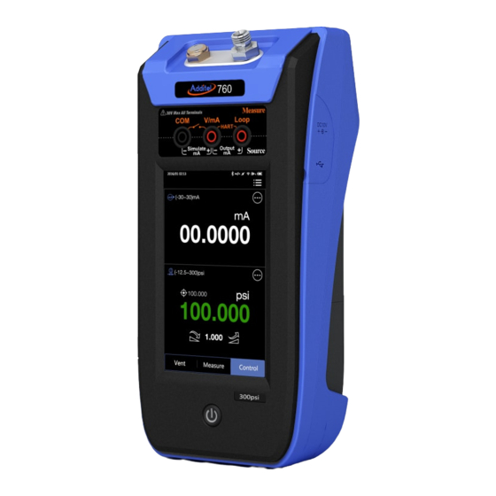
Welcome The Additel 760 Automatic Handheld Pressure Calibrator is a hand held controller, as well as a documenting process calibrator, all rolled into one with high precision and control stability. Each unit comes with an internal pressure module ranged to cover the full scale range of the unit. The internal module is located at the back of the calibrator and is removable allowing for the selection of lower range pressure to improve accuracy. -
Page 13: Safety Information
Safety Information WARNINGS identify action or condition that may be hazards to the user; CAUTIONS identify action or condition that may damage the calibrator or the equipment under test. WARNINGS: To prevent personal injury, please follow this user manual. To prevent possible electrical shock, fire, or personal injury, please: ... - Page 14 CAUTIONS: Do NOT shake, drop, or bump the calibrator while in use If condensation occurs, thoroughly dry out the calibrator before startup Do NOT use any power adapter other than 9816-X Charge the battery immediately when low battery symbol indicates ...
-
Page 15: Table 1 Symbols
Product Symbols Table 1. Symbol Meaning Important information Danger See user manual Risk of electrical shock Hazardous voltage Conforms to European Union directives Please recycle Lithium-ion battery Table 1 Symbols... -
Page 16: Introduction
1. Introduction 1.1 Model Information Model Model No. Pressure Range Pressure Type Low Differential Pressure ±30 inH2O (±75 mbar) D, G Differential Pressure -12.5 to 35 psi (-0.86 to 2.5 bar) D, G General Pressure -12.5 to 300 psi (-0.86 to 20 bar) G, A Table 2 Model Information NOTE: D - Differential;... -
Page 17: Basic Structure
1.2 Basic Structure Figure 1 Basic Structure... -
Page 18: Table 3 Basic Structure
Name Battery Lock Power Switch Touch Screen Electrical Measurement Panel REF Port (-MA: Barometer Sensor Calibration Port) Pressure Outlet Port Power Adapter and USB Port Panel Battery Inlet Port (10) Exhaust Port (11) VENT Port (12) Internal Pressure Module (13) External Pressure Module Connection Ports (A &... -
Page 19: Features
1.3 Features Fully automatic calibrator with built-in pump and controller Switchable internal pressure modules for expandable ranges Accuracy (1 year) of 0.02%FS External pressure modules available (measurement only) Less than 4 lbs. (1.8 kg) for handheld operation ... -
Page 20: Technical Specification
1.4 Technical Specification 1.4.1 General Specification ◆Media:Clean Air ◆Internal module temperature compensation range:32 ~ 122 (0 ~ 50 ℉ ℃ ◆Stability:0.005%FS or 0.05 pa whichever is greater, based on FS of the switchable internal pressure module. ◆Display:5 inch 480 x 800 TFT color touch screen ◆Size:9.37"... -
Page 21: Environment Specification
◆Inlet filter:Dedicated filter,50μm ◆Electrical Measuring Jacks:Φ4 mm electrical jacks ◆USB: Standard USB port, type A ◆External Pressure Module Port: Two 5-pin connections (A & B) 1.4.2 Environment Specification ◆Working Temperature: 32 ~ 122 (0 ~ 50 ℉ ℃ ◆Storage Temperature: -4 ~ 158 (-20 ~ 70 ℉... -
Page 22: Electrical Specification
1.4.3 Electrical Specification Signal Type Range Resolution Accuracy Note Current Measurement ±30 mA 0.0001 mA ±(0.01%RD + 0.005%FS) Input:<10 Ω Voltage Measurement ±30 V 0.0001 V ±(0.01%RD + 0.005%FS) Input:>1M Ω Current Output 24 mA 0.001 mA ±(0.01%RD + 0.005%FS) 20 mA @ 1K Loop Power Source 24 V... -
Page 23: Power
1.5 Power Power Supply:Power supplied by rechargeable Li-Ion battery or an external 10 V power adapter Li-Ion rechargeable battery is removable and can be charged directly using the external power adapter The battery should be removed from the calibrator and charged directly for the fastest charge time ... -
Page 24: Standard Equipment
1.6 Standard Equipment Model Quantity -LLP 760 Calibrator ● ● ● 9724 Rechargeable Li-ion Battery ● ● ● 9816-X External Power Adapter 1 pc ● ● ● 9025 Test Leads 1 set (2 red, 1 black) ● ● ● 2 sets Alligator Clip ●... -
Page 25: Figure 2 Standard Equipment
Figure 2 Standard Equipment... -
Page 26: Get Started
Please remove the battery and store in a cool, dry, ventilated area if it will not be used for a long period Do not store batteries with hazardous or combustible materials Discontinue use and contact Additel or an authorized distributor immediately if the battery leaks Do not short circuit the battery ... -
Page 27: Figure 3 Battery Install And Charging
The Additel 760 Automatic Handheld Pressure Calibrator uses a dedicated rechargeable, Li-Ion battery (model 9724). Each battery has a built-in protection circuit allowing the battery to be charged independent of being attached to the calibrator. Each battery contains an illuminated charge indicator. Push button to see the level of charge. - Page 28 ◆ To Remove the battery: 1) Turn off the calibrator 2) Turn the battery lock to the unlock position with a flat-head screwdriver 3) Remove the battery ◆9816-X External Power Adapter: 1. Input: AC 85V ~ AC 265V, 50Hz / 60Hz 2.
-
Page 29: Internal Pressure Module
2.2 Internal Pressure Module The Additel 760 Calibrator comes with an internal pressure module which covers the full span of the unit. This pressure module is user-switchable and Additel offers a large variety of different range pressure modules. ◆To switch the internal pressure module: 1)VENT the system pressure (see section 5.5.3) -
Page 30: Starting The Calibrator
2.3 Starting the Calibrator Push the power button to turn on the calibrator. The display will illuminate and the Additel logo will display. It will take a few seconds for the operating system to load after which the main screen will display. -
Page 31: Table 6 Electric Connections
Main Jacks Power Supply Jack Function Black(1) Red(2) Red(3) Function ±30 V Voltage ±30 mA Current 2-wire 4 ~ 20 mA Loop Transmitter Non-isolated 24 V 3-wire Voltage/Current Transmitter power output Mechanical Switch ... -
Page 32: Pressure Connection
2.5 Pressure Connection Figure 6 Pressure Connection... -
Page 33: Operation
3. Operation 3.1 Display and Operation 3.1.1 Main Screen The main screen normally contains the Status Bar, Title Bar, Electrical Measurement Window, Pressure Window, and Control Bar. ①Status Bar: Includes date and time, external pressure module status , communication status 24V internal power status , and battery status NOTE: Information on Status Bar is read only. -
Page 34: Figure 7 Main Screen
◆When using one or two external pressure modules, the main screen will add additional windows to display the added module or modules ◆Every window can be collapsed on the top right corner of the window and select collapse ◆Press Press on the top right corner of a collapsed window and select expand to open that window Figure 7 Main Screen... -
Page 35: Pressure Unit
3.1.2 Pressure Unit Press the pressure unit on Pressure Window to change system unit. There are 25 default pressure units which can be selected: kPa, Pa, MPa, hPa, bar, mbar, torr, atm, psi, gf/cm , kgf/cm O@4℃, inH O@68℉, mmH O@4℃, mmH O@20℃, ftH O@4℃, ftH... -
Page 36: Pressure Output
Pressure Window to enter the control settings menu: Subject Valid Value Comment Pressure Type Diff. / Gauge / Absolute The pressure type displayed will depend on the ADT760 model Resolution 4 / 5 / 6 Display digit Slew Rate 0~100%... -
Page 37: Figure 8 Output Connection
2. Connection: Figure 8 Output Connection... - Page 38 3. Pressure Set Point: ①Manual Input: 1)Press pressure set point value or current pressure value on the Pressure Window and input the target pressure. 2)Press the enter key or NOTE: Pressure set point should not exceed pressure range limit shown above the keyboard. ②Manual Step:...
-
Page 39: Table 8 Auto Step
③Auto Step:Press on Pressure Window, then select Auto Step: 1) Auto Step settings: Subject Valid Value Comment Range Depends on internal pressure module The start and end points of auto step Calculation method pressure Step Mode Points/ Percent / Size change of each step Pressure change of each step Points... - Page 40 ◆Auto Step: Press Pause to pause. Press Exit to exit and the calibrator will release the pressure. Press Vent to release the pressure then press Exit to stop the test or Continue to resume the test. 5. Pressure Stabilization: If the difference between current output pressure value and set point is smaller than Stability Limit, the current pressure value on the Pressure Window will turn to green with a beep to indicate the output pressure has reached the set point stability criteria.
-
Page 41: Current/Voltage Measurement
3.1.4 Current/Voltage Measurement 1. Press on Electrical Measurement option ( ) on the top left corner of Electrical Measurement Window and select:(-30~30) mA or (-30~30) V. ◆Do not apply current / voltage that exceeds current / voltage measuring range ◆Apply a short circuit to zero ◆If the measurement value falls outside of the current/voltage measuring range, then it will turn red with an alarm ◆If measure value exceeds measure limit of the calibrator, it will display "--------"... -
Page 42: Table 10 Scale
3. Data Analysis: Press and select one of the functions below: Min / Max / Avg:Shows the minimum, the maximum, and the average ① Subject Valid Value Comment Samples 1~100 Sample collection quantity Table 9 Min / Max / Avg Scale:... -
Page 43: Mechanical Switch
3.1.5 Mechanical Switch 1. Press the Electrical Measurement option ( ) on the top left corner of Electrical Measurement Window and select Switch. 2. Connection Figure 10 Mechanical Switch Measurement 3. Trip Values ◆The calibrator records the trip values and the state (open / close) of the switch. -
Page 44: Npn /Pnp Switch
3.1.6 NPN /PNP Switch 1. Press the Electrical Measurement option ( ) on the top left corner of Electrical Measurement Window and select Switch NPN or Switch PNP. 2. Connection 3. Trip Values ◆The calibrator records the trip values and the state (open / close) of the switch. Figure 11 Electrical Switch Measurement... -
Page 45: Current Output
3.1.7 Current Output 1. Press the Electrical Measurement option ( ) on the top left corner of Electrical Measurement Window and select Simulate mA or (0 ~ 24) mA. 2. Connection: Figure 12 Current Output 3. 24V Internal Power: ◆Simulate mA: Internal 24 V power should be turned off automatically, for more information please see section 5.2 ◆(0~24) mA: Internal 24 V power should be turned on automatically, for more information please see section 5.2... - Page 46 4. Current Set Point: ①Manual Input: 1)Click Measure Value on the Electrical Measurement Window, and input the target value 2)Press ②Manual Step: 1)Press step size on the Electrical Measurement Window and input the current output range 2)Press each time to decrease or increase current output by 25% of range NOTE: Current output range shall not exceed 0~24 mA.
-
Page 47: External Pressure Module
3.1.8 External Pressure Module 1. Connection: Figure 13 External Pressure Module Connection... -
Page 48: Table 11 External Pressure Module Information
2. Display indicate the associated external pressure modules are connected. ◆Symbols The main screen will add one/two additional windows when connecting one/two external pressure module. ◆The external pressure module can only be used for pressure measurement, not for pressure control. ◆If the measurement value falls outside of the range then it will turn red with an alarm. -
Page 49: Hart (Only Available On 760-X-Dl)
3.2 HART (Only available on 760-X-DL) 3.2.1 Poll 1. Connection Figure 14 HART Device (Internal Power, Internal Resistor) -
Page 50: Figure 15 Hart Device (External Power, External Resistor)
Figure 15 HART Device (External Power, External Resistor) 2. HART Device Type Selection: On top of Electrical Measurement Window please press ) and select: Internal Power and Resistor External Power and Resistor... -
Page 51: Operation Window
2. Search 1) Poll Press on Electrical Measurement option ( ) on the top left corner of the Electrical Measurement Window and select HART. The calibrator will poll address 0 if no connection detected. Then it will scan addresses 1 to 15 automatically. 2) Manual Search HART device manual search is available if necessary. -
Page 52: Settings
3.2.3 Settings Press and select Settings to enter HART device settings menu: 1.Device Information: HART device information Subject Type Comment Manufacturer Read Only Manufacturer of HART device Device Type Read Only HART device type Device ID Read Only HART device ID number Editable Alphanumeric content (8 max length) Date... -
Page 53: Table 13 Hart Device Sensor Information
2. Sensor: HART device sensor information Subject Type Comment Sensor Serial Number Read Only HART device sensor SN HART device pressure measurement unit (user selectable, see Sensor Unit Read Only section 3.2.2 Sensor Lower Limit Read Only HART device sensor measurement range lower limit Sensor Upper Limit Read Only HART device sensor measurement range upper limit... -
Page 54: Table 14 Hart Device Output
3. HART Device Output Subject Type Valid Value Comment Select from 25 default units HART device pressure measurement PV / Range Unit Editable or from 5 custom units unit, see section 3.1.2 Within HART device sensor PV LRV Editable Process variable lower range range Within HART device sensor PV URV... -
Page 55: Service
Service to enter HART device service menu: 1. Loop Test: This test allows you to compare the HART device current output value with the ADT760 calibrator current measurement value. ◆The loop test function available only when HART device address is 0 1). - Page 56 3. D/A Trim: This test is designed to trim the HART device current output value at zero and span. ◆D/A Trim function available only when HART device address is 0. ①D/A Zero: 1). Input a current value (4 mA is typical) or select Fetch to capture the calibrator measurement value (on the top right window).
- Page 57 range. 2). Input the calibrator pressure measurement value (on the top left window) or select Fetch to capture the calibrator value to trim the HART device. 3). Press the enter key or select to apply. ③Trim Reset: This feature will reset the HART device back to factory parameters.
-
Page 58: Process
3.2.5 Process Press and select Process to enter the HART device process variable setting menu: Subject Comment Process variable PVAO Digital current value %range Percentage of pressure range Secondary variable Tertiary variable Quaternary variable Loop Current Loop current value Table 15 HART Device Variable ◆Selected process variable will be displayed at the top left corner of Electrical Measurement Window, after the HART- icon... -
Page 59: Zeroing
3.3 Zeroing The zeroing function is available for current/voltage measurement and pressure measurement either internal or external pressure modules. ◆To zero: Press and select ◆Apply a short circuit for current / voltage zeroing ◆Allowable zeroing range: Pressure: within 1%FS; Current / Voltage: within 0.1%FS. 3.4 Vent Press Vent on Control Bar and the calibrator will run the vent process. -
Page 60: Typical Applications
4. Typical Applications The Additel 760 Automatic Handheld Pressure Calibrator supports six typical applications. To start, please select Calibrator under Main Menu , then select the desired application. ◆In the operation interface, press to re-select from the application list ◆In the operation interface, press to enter the new test set up ◆Zeroing:If current / voltage measurement or internal pressure module requires zeroing then press... -
Page 61: Pressure Gauge (Includes Dial And Digital Pressure Gauges)
4.1 Pressure Gauge (Includes dial and digital pressure gauges) In pressure gauge mode, pressure is the only output function available. 1. Pressure Output ◆Ensure proper pressure connections ◆ For pressure output, please see section 3.1.3 and select Jog, which allows for a digit to be selected and numerically ◆Jog:Press incremented, see Figure 16 Figure 16 Jog Function... - Page 62 2.2 Test Execution: After test settings are complete, press to execute the test: 1). Press to zero pressure module if necessary; 2). Press to start the test; ◆The calibrator will pressurize to the first set point (which may be zero) to switch calibration interface ◆Press to check or change test settings...
-
Page 63: Current / Voltage Transmitter
4.2 Current / Voltage Transmitter In the Current / Voltage Transmitter mode, only current, voltage, and pressure are available functions. 1. Current / Voltage Measurement: ◆Correct electrical connection please see Figure 9 ◆Data Analysis:Please see section 3.1.4-3 2. Pressure Output ◆Correct output connection please see Figure 8 ◆Pressure output: Please see section 3.1.3 3. - Page 64 3.2 Test Execution: After test settings are complete, press to execute the test: 1). Press to zero the pressure if necessary. 2). Press to run a manual test, or press to run an automatic test. (1).In manual mode, run next test point by pressing , and the calibrator will automatically record the electrical signal and pressure value.
-
Page 65: Hart Transmitter
4.3 HART Transmitter In HART Transmitter mode, only the Process Variable function and the Pressure function are available. 1. HART Function: ◆Correct electrical connection and HART function, please see section 3.2 2. Pressure Output: ◆Correct output connection please see Figure 8 ◆Pressure output: Please see section 3.1.3 3. - Page 66 1).Press to zero the pressure if necessary. 2).Press to run a manual test, or press to run a automatic test. (1).In manual mode, run the next test point by press calibrator and the calibrator will automatically record the electrical signal and pressure value. (2).In automatic mode, the calibrator will run the test and record the electrical and pressure values automatically without the need to advance the calibrator to the next set point.
-
Page 67: Pressure Switch
4.4 Pressure Switch In the Pressure Switch mode only switch and pressure measurement functions are available. on the top left corner of Switch Measurement window to select the switch type: ◆Press Mechanical Switch, Switch NPN, or Switch PNP. 1. Switch Measurement: ◆Correct electrical connection please see Figure 9 2. - Page 68 3.2 Test Execution: After test settings are complete, press to execute the test: 1). Press to run test automatically to check or change test settings ◆Press 3.3 Report: Once the test is complete the test report interface will appear. For more information, please see section 4.6.
-
Page 69: I/P Converter
4.5 I/P Converter In the I/P Converter mode only pressure and current functions are available. on the top left corner of Current Output window to select the switch type: (0~24) or ◆Press Simulate mA. 1. Pressure Output ◆Correct output connection please see Figure 8 ◆Do not exceed the pressure range of the calibrator ◆Please select Measure on Control Bar 2. -
Page 70: Table 20 I/P Converter Test Settings
Subject Valid Value Comment Input Depends on UUT UUT current measuring range Output Depends on UUT UUT pressure output range Transfer Function Linear / Square Root Transfer function type Table 20 I/P Converter Test Settings ②Test Method: See section 3.1.3-3-③Auto Step 3.2 Test Execution: After test settings are complete, press to execute the test:... -
Page 71: Documenting
4.6 Documenting Once the test is complete the test report interface will appear. ◆Report interface can be switched between chart view and data view by pressing ◆The test results will be canceled and the test will restart by pressing ◆Report results are saved by pressing and entering the information below 1. -
Page 72: Table 22 Test Save Options
2. Save Options: Subject Valid Value Comment Operator Alphanumeric content (16 max length) Test operator ID Execute Date 2000/01/01 ~ 2099/12/31 Execution date Environment temperature during test , Temperature -20 ~ 100 unit: ℃ Humidity 0 ~ 100 Environment humidity during test Table 22 Test Save Options ◆Results can be recorded as As Found, As Left or Both (As Found and As Left) -
Page 73: Setup
5. Setup To enter the setup menu, please select Setup under Main Menu ◆Any changes made in the Setup will become the default values after the calibrator is rebooted. 5.1 Control Settings See section 3.1.3-1 5.2 24V Power To turn on or turn off internal 24V power supply. -
Page 74: Communication
5.3 Communication Communication settings: Subject Valid Value Comment WLAN Settings WLAN On / Off Enable or disable Wi-Fi communication function Depends on network environment SSID Select Wi-Fi router (only available when WLAN is on) Network Port 760 calibrator network port, read only 760 calibrator MAC address, read only Advanced DHCP / Static... -
Page 75: Head Correction
5.4 Head Correction Head pressure correction can be enabled or disabled. ◆If head pressure correction is enabled: Subject Valid Value Comment Correction Type Auto / Fixed Head pressure correction value calculation type Correction Type: Fixed Depends on internal Correction Value Fixed correction value pressure module Correction Type: Auto... -
Page 76: Services
"----/--/--" ◆A higher accuracy standard should be used to calibrate the ADT760 calibrator ◆The calibration operation password is: 123456 ◆Once the calibration is completed and saved the new data will be immediately loaded and used. A new calibration date will also be uploaded ◆Once a new calibration has been finished and saved any previous calibrations will be permanently deleted... - Page 77 ◆3 points for current / voltage measurement calibration ◆Default current measurement calibration points are -30 mA, 0 mA, 30 mA Default voltage measurement calibration points are -30 V, 0 V, 30 V ◆Additel does not recommend changing calibration points. 3. Calibration Execution: 1). Press to start calibration process 2).
- Page 78 Select the calibration point which needs to be changed, then input value ◆3 points for current output calibration ◆Default current output calibration points are 1mA, 10mA, 20mA ◆Additel does not recommend changing calibration points. 3. Calibration Execution: 1). Press to start calibration process 2).
- Page 79 5.5.1.4 Auto Tune This function is only used during when recommended by Additel Corporation to service the calibrator 5.5.1.5 Pressure Sensor This function is for positive and negative pressure sensor check with atmosphere.
-
Page 80: Figure 17 Barometer Sensor Calibration
◆2 points for current output calibration ◆Default calibration points are 60kPa and 110kPa ◆Additel does not recommend changing calibration points 3. Pressure Outlet: The output pressure from the standard needs to be the same as the corresponding calibration set points. When the Measured Value is stable, enter the Reference... -
Page 81: Diagnosis
This menu provides diagnostic information from the main board, control board, and electrical board which may help indicate if anything is working improperly. ◆If a problem is detected then please contact Additel for further assistance ◆More information: 1. Password: 123456 5.5.3 System Log... -
Page 82: Maintenance
5.5.4 Maintenance This menu is used to depressurize the unit when switching internal pressure models. to start. ◆Press 5.5.5 Factory Reset Resets all data to factory default settings. ◆Password:123456 5.5.6 Updates To update 760 calibrator firmware, please: 1). Copy update file into an USB root directory 2). -
Page 83: Sound
5.6 Sound To enable or disable Touch Beep and Over range alarm beep. 5.7 Personalization 5.7.1 Date and Time Subject Valid Value Comment Time 0:00 ~ 23:59 Time Date 2000-1-1 ~ 2099-12-31 Date Date Format YYYY-MM-DD / MM-DD-YYYY / DD-MM-YYYY Date format Date Separator -, /, . -
Page 84: Safety Data
5.7.4 Safety Data Switch ON/OFF a warning before data deletion. 5.8 Power Management Subject Valid Value Comment Brightness 1~100% Adjusting this setting may impact the battery life. Battery Information: remaining capacity, full capacity, Battery Info temperature, voltage, cell voltage I & II, Charging / Discharging Current Never, 15 sec, 30 sec, 1 Auto Backlight Off... -
Page 85: System Information
5.9 System Information 1. Main: Main information of 760 calibrator: including serial number, application, system version, Wi-Fi, BLE (Bluetooth), control board, electric board information 2. Battery: Battery information: including serial number, version, manufacture date information. 3. Internal module: Internal pressure module information: including range, pressure type, accuracy, serial number, version, manufacture date information. -
Page 86: Task (Only Available On 760-X-Dl)
6. Task (Only available on 760-X-DL) The Additel 760 calibrator provides task functionality for automated calibration while storing and archiving the calibration data. To use the task function, please select Task under Main Menu 6.1 New Task Press and select UUT (Unit Under Test) type to enter a New Task interface and add UUT... -
Page 87: Dial Pressure Gauge
6.1.1 Dial Pressure Gauge UUT (Unit Under Test) information: Subject Valid Value Comment Name Enter an alphanumeric content (16 max length) UUT ID Serial Number Enter an alphanumeric content (16 max length) UUT serial number Location Enter an alphanumeric content (16 max length) Task location Note Enter an alphanumeric content (16 max length) -
Page 88: Digital Pressure Gauge
6.1.2 Digital Pressure Gauge Please see section 6.1.1. Press to complete UUT information set up and the calibrator will switch back to the task list. For further instruction, please see section 6.2.2. -
Page 89: Pressure Transmitter (Current, Voltage, Hart)
6.1.3 Pressure Transmitter (Current, Voltage, HART) UUT (Unit Under Test) information: Subject Valid Value Comment Name Enter an alphanumeric content (16 max length) UUT ID Serial Number Enter an alphanumeric content (16 max length) UUT serial number Location Enter an alphanumeric content (16 max length) Task location Note Enter an alphanumeric content (16 max length) -
Page 90: Pressure Switch
6.1.4 Pressure Switch UUT (Unit Under Test) information: Subject Valid Value Comment Name Enter an alphanumeric content (16 max length) UUT ID Serial Number Enter an alphanumeric content (16 max length) UUT serial number Location Enter an alphanumeric content (16 max length) Task location Note Enter an alphanumeric content (16 max length) -
Page 91: I/P Converter
6.1.5 I/P Converter UUT (Unit Under Test) information: Subject Valid Value Comment Name Enter an alphanumeric content (16 max length) UUT ID Serial Number Enter an alphanumeric content (16 max length) UUT serial number Location Enter an alphanumeric content (16 max length) Task location Note Enter an alphanumeric content (16 max length) -
Page 92: Task Execution
6.2 Task Execution Please select UUT(Unit Under Test) from the task list, and check UUT information. Next select view and or edit the task information and execute the test. ◆To edit UUT information, please select UUT from the task list then select 6.2.1 Dial Pressure Gauge 1. - Page 93 2. Task Execution: Press to execute the task: 1). Press to zero pressure module if necessary 2). Press to start the test; ◆The calibrator start pressurizing to the first test point to switch calibration interface ◆Press 3). Standard test steps: (1).
-
Page 94: Digital Pressure Gauge
6.2.2 Digital Pressure Gauge 1. Task Execution Setup (Run Information): Subject Valid Value Introduction 2~17; Set point values will be calculated automatically. Set point values depend on ◆To edit the number of set points press: press or press on Set Set Points UUT range point number at the bottom of the screen and input value... - Page 95 (3). After the pressure is stable enter the UUT value. (4). Repeat step 2 and 3 until all test points are completed. 3. Report: Once a test is complete, the test report interface will appear. For more information please see section 6.4.
-
Page 96: Pressure Transmitter (Current, Voltage, Hart)
6.2.3 Pressure Transmitter (Current, Voltage, HART) 1. Task Execution Setup (Run Information): Subject Valid Value Comment Set point values will be calculated automatically. 2~17; ◆To edit the number of set points press: press Set point values depend Set Point or press on set point number at the on UUT range bottom of the screen and input value ◆To edit value: select and input value... - Page 97 to switch calibration interface ◆Press 3. Report: Once a test is complete, the test report interface will appear. For more information please see section 6.4.
-
Page 98: Pressure Switch
6.2.4 Pressure Switch 1. Task Execution Setup (Run Information): Subject Valid Value Comment Repeat 1 / 2 / 3 Task cycle times Switch(Mechanical Switch) / Switch Select Current Source Channel Pressure switch type PNP / Switch NPN Table 34 Pressure Switch Task Settings 2. -
Page 99: I/P Converter
6.2.5 I/P Converter 1. Task Execution Setup (Run Information): Subject Valid Value Comment Set point values will be calculated automatically. 2~17; ◆To edit the number of set points press: press Set point values depend on Set Points or press on set point number at the bottom of the UUT range screen and input the value ◆To edit the value: select and input value... -
Page 100: Task Delete
signal and pressure value automatically. (2).In automatic mode, the calibrator will run the test and record electrical signal and pressure value automatically. to switch calibration interface ◆Press 3. Report: Once a test is complete, the test report interface will appear. For more information please see section 6.4. -
Page 101: End Of Task
6.4 End of Task Once a test is complete, the test report interface appears. ◆Report interface can be displayed in a chart or data format by pressing ◆The test data can be canceled and the test will restart by pressing ◆To save the report press and enter the information below: Save Options:... -
Page 102: Data Logger (Only Available On 760-X-Dl)
7. Data Logger (Only available on 760-X-DL) To use data logger function, please select Data Logger under Main Menu 1. The data logging functions available are listed below: ①Electrical Signal: Current / voltage measurement, pressure switch (mechanical, PNP, NPN) measurement, current output (0~24 mA, simulate mA), and HART device electrical signal are available for data logging. -
Page 103: Table 37 Data Logger Setup
Subject Valid Value Comment Trigger Periodic Data logger activate type, read only Interval 0.1~999999 Data logging internal, unit: sec Samples 1-999999 Data logging sample number Time 0:00:00~999:59:59 Data logging total time span Table 37 Data Logger Setup NOTE:Interval x Samples = Times 4. -
Page 104: Application
8. Application To use additional applications, please select Application under Main Menu 8.1 Leak Test Leak test is used to check the leak rate in the calibration system. To start a test, press the > in the top right portion of the leak test screen. this will allow you to modify the following parameters. -
Page 105: Pressure Unit Converter
8.2 Pressure Unit Converter Each Additel 760 calibrator has a built-in pressure unit converter. ◆Press on any unit and input the value you would like to convert to... -
Page 106: Service
9. Service 9.1 Inlet Port Filter Figure 18 Inlet Port Filter To change inlet port filter: 1). Remove battery and screw 1 and 2 by using Allen Key (2.5mm) 2). Remove back cover 3). Change the filter Maintenance Cycle: 3 ~ 6 months depending on use. -
Page 107: Pressure Outlet Port Filter And O-Ring (Same As Ref Port)
9.2 Pressure Outlet Port Filter and O-ring (Same as REF port) Figure 19 REF and Outlet Port Filter To change pressure outlet port filter and o-ring: 1). Remove pressure outlet port by turning in counter-clockwise direction 2). Push out the filter by using Allen Key (≤2.5mm) 3). -
Page 108: Appendix 1: Scpi List
Appendix 1: SCPI List NOTE: In the system, pressure unit is an independent parameter. Current / voltage unit is used as a parameter along with its numerical value. A1.1 IEEE488.2 Command Description Parameter Return Value The command removes the following register: Standard event register;... - Page 109 Command Description Parameter Return Value return data shall be divided into 2 parts: and software Ver. No. a.Product series No; b.Software version No. After equipment implements *OPC *OPC command, set the “operation complete” of standard event register at 1. *OPC? After *OPC? Order, return to 1.
-
Page 110: A1.2 Measurement And Configuration
A1.2 Measurement and configuration Command Description Parameter Return Value Pressure measurement. n valuing 1~6. PRESsure1 means reading the pressure of pressure module under control (the value adjusted by air column under the currently set pressure type); PRESsure2 means reading the pressure of internal module (as original value);... - Page 111 Command Description Parameter Return Value receiving command, controller sets the measurement item as measurement, conduct measurement, return measurement value. current measurement only range (-30~30) mA, displaying the fixed bit width of 6. MEASure[:SCALar]:VOLTa Measurement Voltage measurement value MEASure[:SCALar]:SWITc 1:Open; Mechanical Switch status test h:REGular? 0:Close.
- Page 112 Command Description Parameter Return Value measurement; “CURRent:SOURce”:cu rrent output “VOLTage” : voltage measurement within (-300~300)mV range; “SWITch:REGular”: Switch tes; “SWITch:PNP”: PNP switch test; “SWITch:NPN”: NPN switch test. SENSe:ElECtricity:FUNCti Read measurement type Pressure type switching, n=1~3 ABSolute:Absolute SENSe:PRESsure<n>:MO 1. Internal pressure module pressure;...
- Page 113 Command Description Parameter Return Value 2. External pressure module A 3. External pressure module B Set pressure value display bit wide. 7 bit is only available for quartz pressure Bit wide: SENSe:PRESsure<n>:DIG module. MIN stands for n=1~3 minimum bit wide; 4|5|6|7|MINimum|MAXim 1.
- Page 114 Command Description Parameter Return Value current pressure control module. n=1~3 1. Internal pressure module 2. External pressure module A 3. External pressure module B Zero current electrical measurement SENSe:ElECtricity:ZERO value MINimum stands for minimum range; SENSe:VOLTage[:DC]:RA MAXimum stands for Lower limit, upper NGe? Read voltage measurement range maximum range;...
- Page 115 Command Description Parameter Return Value 3. External pressure module B Read pressure module version. n=1~3 SENSe<n>:VERSionSW|H SW:Software Version 1. Internal pressure module HW:Hardware Version 2. External pressure module A 3. External pressure module B...
-
Page 116: A1.3 Output
A1.3 Output Command Description Parameter Return Value Pressure value: [SOURce:]PRESsure<pres Set targeted pressure value and output <numeric_value>, sure_value> pressure. unit is the current set unit of system [SOURce:]PRESsure? Read target pressure value Target value, unit [SOURce:]PRESsure:LIMit: Read pressure output upper limit Upper limit, unit UPPer? [SOURce:]PRESsure:LIMit:... - Page 117 Command Description Parameter Return Value pressure control rate if ignore this parameter Max: Maximum [SOURce:]PRESsure:SLEW rate Set pressure control rate type :TYPEMAX|CUSTom Custom: Custom rate [SOURce:]PRESsure:SLEW Pressure control rate Read pressure control rate type :TYPE? type Pressure stability: [SOURce:]PRESsure:TOLe Set pressure stability <numeric_value>...
- Page 118 Command Description Parameter Return Value 1 or HITH:High OUTPut:GPIO<n>[:STATu Set IO port status, n=1~30, stands for the electrical level; IO port pin position. For example, GPIO2 0 or LOW:Low <Boolean>|LOW|HIGH stands for the second pin of IO port. electrical level 1:High electrical OUTPut:GPIO<n>[:STATu Read IO port status...
-
Page 119: A1.4 Calculation
A1.4 Calculation Command Description Parameter Return Value Pressure lower CALCulate[:PRESsure]:LI limit, unit is the Set pressure lower limit Mit:LOWer<low> current set unit of system CALCulate[:PRESsure]:LI Pressure lower limit, Read pressure lower limit Mit:LOWer? unit Pressure upper CALCulate[:PRESsure]:LI limit, unit is the Set pressure upper limit Mit:UPPer<high>... -
Page 120: A1.5 System
Command Description Parameter Return Value unit is the current set unit of system CALCulate[:PRESsure]:LI Read venting pressure Venting pressure, unit Mit:VENT? A1.5 System Command Description Parameter Return Value “APPLication”: Main program version “CONTroller:FIR Mware”: Read module SCPI Ver No.. SYSTem:VERSion? Controller Default is the system SCPI version number Version number... - Page 121 Command Description Parameter Return Value ware”: Electrical measurement board firmware version “ElECtricity:HARD ware”: Electrical measurement board hardware version Check next error item in the error queue, and delete the item from the queue. The error queue can store 50 pieces of error SYSTem:ERRor[:NEXT]? information.
- Page 122 Command Description Parameter Return Value 0 or OFF: Unlock screen 1:Lock SYSTem:KLOCk? Read screen lock status 0:Unlock 1 or ON: SYSTem:MAINtenance:M Maintenance start Set system maintenance status ODE<Boolean>|ON|OFF 0 or OFF: Maintenance stop Outlet pressure, positive, and negative pressure venting status SYSTem:MAINtenance:ST Read system maintenance status...
- Page 123 Command Description Parameter Return Value communicate with controller through the WIFI Ethernet. SYSTem:COMMunicate:S Read WIFI Status 1: WIFI is on; OCKet:WLAN[:STATe]? 0: WIFI is off SYSTem:COMMunicate:S Set WIFI IP address IP address: OCKet:WLAN:ADDRess<I Without quotation P address> marks, the format <NR1>.<NR1>.<...
- Page 124 Command Description Parameter Return Value SYSTem:COMMunicate:S Set WIFI gateway IP address: OCKet:WLAN:GATeway Without quotation <IPaddress> marks, the format <NR1>.<NR1>.< NR1>.<NR1> SYSTem:COMMunicate:S Read WIFI gateway IP address OCKet:WLAN: GATeway? SYSTem:COMMunicate:S Read WIFI MAC address MAC address OCKet:WLAN:MAC? SYSTem:COMMunicate:S Set WIFI DHCP status 1 or ON: DHCP on;...
- Page 125 Command Description Parameter Return Value connection name and SSID encryption, no connection or not to return to the hot search"" SYSTem:COMMunicate:S Connect to specific hot spot 1)ssid: Hot spot OCKet:WLAN:CONNect name, string with <ssid>,encryptionMode[ quotation marks; ,<password>] encryptionMode: encryption method, OPEN|WPA|WPA2;...
- Page 126 Command Description Parameter Return Value ScaningConfiguredSSI WaitingIPConfiguratio ModuleJoinedListenin gSockets SYSTem:COMMunicate:S Disconnect WIFI OCKet:WLAN:DISConnec SYSTem:COMMunicate:S Read WIFI DBM value DBM value,uint is OCKet:WLAN:DBM?
-
Page 127: A1.6 Status
A1.6 Status Command Description Parameter Return Value Enable value: STATus:OPERation:ENABl Set operation status enable register <numeric_value>, e<enable value> 0-65535 STATus:OPERation:ENABl Read operation status enable register <enable value>:NR1 Read the value of operation status register. STATus:OPERation[:EVENt On execution of the command, the value of <value>:NR1 operation status register shall be reset. -
Page 128: A1.7 Unit
A1.7 Unit Command Description Parameter Return Value Unit: Can be a unit name or unit ID, UNIT:PRESsure<n><unit unit name is a Set pressure unit _name>|<unit_ID> string with quotes, unit ID is number. UNIT:PRESsure<n>? Read pressure unit Unit name Read system unit ID n= 1~3 UNIT:PRESsure<n>:ID? 1. -
Page 129: A1.8 Data Record
A1.8 Data Record Command Description Parameter Return Value DATALOGGER:COUNt? Read the total Result quantity number of data records DATALOGGER:CATalog? Index: Starting position count:Qty.(0-5) Read data record ClassName,Base64 <Index>,<count> brief information character data,CRC16 (GUID, record check code (Data name, operator, obtained by anti notes, record serialization) time, sampling... - Page 130 Command Description Parameter Return Value time (less than 750 bytes) be converted into an array of byte, and then converted to float values for presentation) DATALOGGER:DELete<gui guid:Unique identifier for data records Delete record d> DATALOGGER:CLEar Clear all records DATALOGGER:SEARchcou Condition:Condition, strings with quotation Number of Result quantity nt ?
- Page 131 Command Description Parameter Return Value DATALOGGER:SEARchcount? "0,test;1,sun;2,heihei;3,2000/01/28,2016/10/ 28” "DATALOGGER:SEARchinfo Conditon: Same as above Read the brief ClassName,Base64 [:ECHO]? Index: Starting position count:Qty.(0-5) information that character data,CRC16 < Condition>,< Index>,< satisfies the check code (Data count>" condition data obtained by anti record serialization)
-
Page 132: A1.9 Hart
A1.9 HART Command Description Parameter Return Value HART:SUPPLYMODE? Read power 0: Internal; 1: External; supply type HART:SUPPLYMODE 0 or Int:Internal; Set power supply Int|Ext|0|1 1 or Ext:External; type (the electrical measurement will switch to HART measurement if power supply type is changed)... - Page 133 Command Description Parameter Return Value type) HART:CONnect<address> Address: Connect to searched device HART:ONLDEVice:PROCes PV or 0: Process variable; AO or 1:Digital current value; % or 2:Percentage of pressure range; SV or 3:Secondary variable; TV or 4:Tertiary variable; FV or 5:Quatemary variable;...
- Page 134 Command Description Parameter Return Value ter? <name> HART:ONLDEVice:PARame name: parameter name Set parameter ter[:ECHO] <name>,< value: Value (with a quoted string, or “value”>|<value> number) HART:ONLDEVice:INFO? No or < parameter name > parameter name Return HART Returns all device listed below: device information information values when no parameters...
- Page 135 Command Description Parameter Return Value HART:ONLDEVice:SENSor? No or < parameter name > parameter name Return sensor Returns all device listed below: information information values when no parameters unit are entered; Corresponding parameter values minspan returns when the parameter name is specified;...
-
Page 136: Appendix 2: Unit
Appendix 2: Unit Unit Name Unit Name in System Unit ID in System 1130 1133 1132 1136 1137 mbar mbar 1138 torr torr 1139 1140 1141 gf/cm 1144 kgf/cm 1145 O@4°C INH2O 1147 O@68°F 1148 O@4°C 1150 O@20°C mmH2O@20C 1151 O@4°C ftH2O@4°C 1153... - Page 137 Unit Name Unit Name in System Unit ID in System mmHg@0°C 1158 mtorr mtorr 2001 lb/ft lb/ft2 2002 2003 2004 O@60°F inH20@60°F 2005 O@60°F ftH20@60°F 2006...
-
Page 138: Appendix 3: Software
Appendix 3: Software The Additel 760 calibrator can work with 4 Additel software: Data Logging Task Management Calibration Control Uploading Downloading Program Export Recording (760 Computer) (Computer 760) → → ACal √ √ √ √ PCal √ Land √ √... - Page 139 The ADT760 communicates with Additel software via a standard USB cable. Additel offers a cable below. Order Info: Model Number Description Picture 1311000019 USB to USB cable, 1 meter ◆ Please connect ADT760 to computer by a USB to USB cable ◆...
-
Page 140: A3.1 Additel Acal
A3.1 Additel ACal Step 1. Additel/ACal must be updated to version 1.1.2980 or later Step 2. Follow ACal user manual and select ADT760 as reference Step 3. Click on "Start Cal", then click on the Manual Install icon... - Page 141 Step 4. Double click on "zadig.exe" Step 5. Follow section A3.5 to install ADT760 driver...
- Page 142 Step 6. Close the "zadig" program and the folder and check the driver status in ACal Step 7. After the ADT760 driver has been successfully installed, please follow ACal user manual for further operation.
-
Page 143: A3.2 Additel Pcal
A3.2 Additel PCal Step 1. Additel/PCal must be updated to version 1.5.7 or later Step 2. Click on Calibration Wizard... - Page 144 Step 3. Select UUT (Unit Under Test) type, then wait few seconds for the auto calibration reference detection...
- Page 145 Step 4. Click on "Manual Install"...
- Page 146 Step 5. Double click on "zadig.exe" Step 6. Follow section A3.5 to install ADT760 driver Step 7. Close the "zadig" program and the folder, then click on "Re-Detect" and wait for few seconds...
- Page 147 Step 8. Close the window and wait few seconds for re-detection Step 9. When the ADT760 driver has been installed successfully, please follow PCal user manual for further operation.
-
Page 148: A3.3 Additel Land
A3.3 Additel Land Step 1. Additel Land must be updated to version 3.5.8 or later Step 2. Click on "Scan", then click on "Manual Install"... - Page 149 Step 3. Double click on "zadig.exe" Step 4. Follow section A3.5 to install the ADT760 driver Step 5. Close the "zadig" program and the folder, then click on "Re-Detect" and wait for few seconds...
- Page 150 Step 6. Close the window and wait few seconds for re-detection Step 7. When the ADT760 driver has been installed successfully, please follow Land user manual for further operation.
-
Page 151: A3.4 Additel Log Ii
A3.4 Additel Log II Step 1. Additel Log II must be updated to version 2.4.1 or later Step 2. Wait for few seconds, then click on "Manual Install"... - Page 152 Step 3. Double click on "zadig.exe" Step 4. Follow section A3.5 to install the ADT760 driver Step 5. Close the "zadig" program and the folder, then click on "Re-Detect" and wait for few seconds...
- Page 153 Step 6. Close the window and wait few seconds for re-detection Step 7. Please follow Log II user manual for further operation.
-
Page 154: A3.5 How To Install Adt760 Driver By Using Zadig
A3.5 How to install ADT760 Driver by using Zadig We suggest a third party software which is called Zadig to simplified ADT760 driver installation. This software is packed into all Additel software, no additional download required after initial installation. Step 1. - Page 155 Step 2. Select "No" to skip update process.
- Page 156 Step 3. In the first red Frame ,select “Generic Serial(PROTOTYPE—Remember to change idVendor)”, In the second red Frame, select “Install Driver”.
- Page 157 Step 4. Select “Always trust software”, and Click “Install” button. Wait for a few seconds for the driver installation.
- Page 158 Check: In "Device manager" panel, there is a new option which means the Device drive has been installed successfully. Test Equipment Depot - 800.517.8431 - 99 Washington Street Melrose, MA 02176 TestEquipmentDepot.com...
Need help?
Do you have a question about the ADT760 and is the answer not in the manual?
Questions and answers