Table of Contents
Advertisement
Advertisement
Table of Contents

Related Manuals for Additel ADT761-D


Summary of Contents for Additel ADT761-D
- Page 1 ADT761 Series Automated Pressure Calibrator...
- Page 2 ADT761 Series Automated Pressure Calibrator User Manual Please download the latest version from www.additel.com [Version: 1709V05] Additel Corporation...
- Page 3 This technical manual provides operating and safety instructions for the ADT761 Series Automated Pressure Calibrator. To ensure correct operation and safety, please follow the instructions in this manual. Additel reserves the right to change the contents and other information contained in this manual without notice.
- Page 4 CONTENTS Warnings ............................. 1 General safety ..........................2 1. Introduction ..........................3 1.1 Overview ............................... 3 1.2 Features ..............................3 1.3 Specifications ............................4 2. Installation ..........................5 2.1 Features ..............................5 2.1.1 Basic structure ............................5 2.1.2 Electrical terminals and signal interface ....................6 2.1.3 RS-232 interface ..........................
- Page 5 3.1.2 Pressure output ..........................12 3.1.3 Pressure measure ..........................13 3.1.4 Pressure unit .............................14 3.1.5 Current output ...........................14 3.1.6 Current / voltage measure ........................15 3.1.7 Switch test ............................15 3.1.8 External pressure module ........................16 3.1.9 Scaling .............................17 3.1.10 Zero ...............................17 3.1.11 Step ...............................17 3.1.12 Snapshot ............................19 3.1.13 Vent ...............................19 3.2 HART..............................20...
- Page 6 3.4.3 Display setup ............................29 3.4.4 Date and time ............................30 3.4.5 Language ............................31 3.4.6 Factory default ..........................31 3.4.7 Tools ..............................31 3.4.7.1 Leak test ............................31 3.4.7.2 Vent ............................33 3.4.7.3 Unit conversion ..........................33 3.4.7.4 Help ............................34 3.4.8 Information ............................34 3.4.9 System Calibration ..........................34 3.4.9.1 Current / voltage measure ......................35 3.4.9.2 Current source ..........................35 3.4.9.3 High / low range ...........................35...
- Page 7 4.3 Checking system for leaks ........................48 4.3.1 Checking for leaks ..........................48 4.4 Instability ............................49 5. Special Application for Barometric Pressure ................50 5.1 ADT761 Basic differences........................50 5.2 Gas head correction ..........................50 5.3 Specific ADT761-BP applications......................50 5.3.1 Digital barometer ..........................50 5.3.2 Mercurial barometer .........................52 5.3.3 Aneroid barometer ...........................53 5.3.4 Barometer altimeter .........................54 5.3.5 Pressure transmitter ........................55...
-
Page 8: Warnings
Do not combine with another pressure source where pressure is being generated by both sources at the same time. Additel's warranty will not cover this application. Do not apply pressures greater than the maximum working pressure. Additel's warranty will not cover this application. -
Page 9: General Safety
Do not apply excessive voltage or current to the electrical terminals. Do not use any adapter other than Additel model 9818. Charge as soon as the battery symbol indicates. If the calibrator is not working properly, turn it off, remove the battery and contact Additel. -
Page 10: Introduction
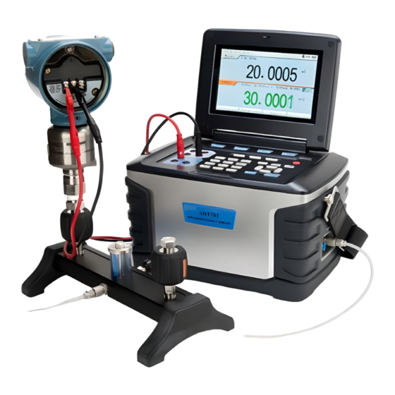
The ADT761 Series Automated Pressure Calibrator generates pneumatic pressure rapidly with high precision and stability. Precision measurement and digital control technology developed by Additel are used in the ADT761. With dual pressure sensors, precision electrical measurement and source, the ADT761calibrator provides many different ways to calibrate and test a variety of devices such as, dial pressure gauges, digital pressure gauges, pressure transmitters, pressure switches and I/P converters. -
Page 11: Specifications
0.1 to 3.5 bar.a (1.7 to 50 psi.a) 0.1 to 41 bar.a (1.7 to 615 psi.a) ADT761-BP 100 to 1200 hPa 100 to 1200 hPa Additel reserves the right to change specifications and other information contained in this manual without notice. -
Page 12: Installation
2. Installation 2.1 Feature 2.1.1 Basic structure Status Bar Measure Source Function Keys Shortcut Keys On Off Measure terminals HART, Task and Setup keys Source terminals Control Keys Numeric Keypad Lock Strap Connections Rs232 Interface Vent Port Pressure module Portable Automated Pressure Calibrator connection /FLT Outlet Port... -
Page 13: Electrical Terminals And Signal Interface
2.1.2 Electrical terminals and signal interface Terminal and Interface Introduction 6 and 2 Current measure. 1 and 2 Voltage measure. 5 and 2 Switch test. 3 and 6 HART communication. 7 and 4 Current output (external power). 3 and 7 Current output (internal power). -
Page 14: Keypad
2.1.4 Keypad Table 2-3 Key functions... -
Page 15: Pneumatic Port
2.1.5 Pneumatic port OUTLET port: The calibrator provides the controlled pressure output to the UUT. The range of the pneumatic volume for control is (0~100) cc and should not be exceeded. REF/FLT port: ADT761-BP (port is blocked). ADT761-LLP/D (port is the reference or low port. Leave open to measure in gauge mode). -
Page 16: Changing The Belt Strap
Figure 2-7 Pneumatic connection 2.2.3 Pneumatic connection As shown in Figure 2-6 shows pneumatic connection of ADT761-LLP and ADT761-D.Figure 2-7 shows pneumatic connection of ADT761-L, ADT761-LA, ADT761-M, ADT761-MA, ADT761-H and ADT761-HA., connect the OUTLET and REF/FLT ports to the UUT or use plugs when necessary. -
Page 17: Getting Started
2.3 Getting started 2.3.1 Power on Press to turn the power on. The startup screen shows the manufacturer's logo. After a short time the system enables the home screen and enters STANDBY mode as shown in Figure 2-8. Connect the power supply for charging if power is low. 2.3.2 Setting the system date and time Refer to section 3.4.4 to set date and time. -
Page 18: Function And Operation
3. Function and Operation 3.1 Display and basic operation 3.1.1 Home Screen The home screen normally contains a MEASURE window and a SOURCE window (see figure 3-1). If you select the Triple Display in the SETUP mode and connect the external pressure module, three windows will be shown (see figure 3-2). -
Page 19: Pressure Output
Function keys: Status bar: Run mode (not visible in the home screen), snapshot, HART online, pressure module online, 24V power status, battery level. Triple display: If the triple display is enabled, then three windows will be shown when the pressure module is connected. The pressure output mode: Press to change to standby mode, exit the control mode, or to vent the calibrator. -
Page 20: Pressure Measure
If you've selected the low pressure sensor and enter a pressure value that exceeds the low sensor range, then the calibrator will ask if you would like it to automatically switch to the high pressure sensor. 4. Control Confirm the set value, and the calibrator will automatically start controlling to the set point. The control may be paused at any time by pressing The following functions are disabled in the CONTROL mode: Pressure Zero (Section 3.1.10), Step (Section 3.1.11), Leak Test (Section 3.6.1), VENT (Section 3.6.2), and Calibration (Section 3.7). -
Page 21: Pressure Unit
3.1.4 Pressure unit Press to select a pressure unit in the SOURCE window,or when measuring an external pressure module in the MEASURE window. The selected units relate to the range and resolution of the internal sensors (Section3.4.3). 3.1.5 Current output 1. -
Page 22: Current / Voltage Measure
3.1.6 Current/voltage measure 1. Selected Current or Voltage in MEASURE mode. Do NOT apply voltage / current that exceeds the current / voltage range. Press to zero. If the value falls outside the current/voltage range, the color of the display value will change from black to red and the calibrator will issue the alarm. -
Page 23: External Pressure Module
3. Trip values The switch test will only work if the SOURCE window is set to source pressure. The calibrator records the trip values and the state (open/close) of the switch. Press to erase trip values. 3.1.8 External pressure module 1. -
Page 24: Scaling
3. Operations Press to select a pressure unit (Section 3.1.4 and Table 3-2). Press to display the information of the pressure module. 3.1.9 Scaling When a current or voltage is being measured, the calibrator can scale the signal to display pressure or % of full scale. Press to set correlative parameter. - Page 25 2)The step of engineering unit(E), and the output values(n): Vmin+ (n-1) * E, n = 1 2 … (n-1) * E 3)The step of scale(P), and the output values(n): Vmin+ ( Vmax-Vmin ) * (n-1) * P%, n = 1 2 … (n-1) * P% note: The range must be divisible by the step size.
-
Page 26: Snapshot
Press to delete the record(s). /FLT The record(s) can be uploaded to a computer by the RS232 port to Additel/Land software. 3. Prefix Press to add a prefix to the file name. Allows for an alphanumeric entry or press numerical keypad to input special codes. -
Page 27: Hart
Do not point the Vent port toward the operator during venting. Will end the leak test. Press to stop any pressure generation or control and return to barometric pressure. Press again to close the vent valve and switch to Standby mode. When setting a decreasing pressure value, the calibrator will Figure 3-13 Internal series resistor automatically vent when the pressure reaches the Vent P... -
Page 28: Process Variables
2. Poll Ensure a proper connection (see connections above). From the home screen, press to start the HART function. The calibrator will poll address 0. If no connection is made, it will scan from address 1 to 15. Once the calibrator establishes communication with the transmitter, the transmitter will be added into the HART device list. -
Page 29: Setup
3.2.3 Setup 1. Parameters Press to setup the following functions. Category Sub Category Read Only or Read and Write Description MFR (Manufacturer) N A / Read only Transmitter manufacturer N A / Model Read only Manufacturer model number Device id N A / Read only Manufacturer device id... -
Page 30: Service
2. Operations Press to view the HART parameters, and press to open the setting status. In the setting status press to select and press to set. If the operation is canceled or fails, the value of the parameter will be reset. 3.2.4 Service 1. -
Page 31: Typical Applications In The Main Screen
Some transmitters do not support the sensor trim function. A Sensor Trim can involve one or more trim points according to different transmitters. Support to change the PV unit and pressurize mode (Internal pressure source or External pressure source). The trim points in the internal pressure source mode cannot exceed the control range of the Control Setup, or the calibrator will prompt the user to reset limits. -
Page 32: Calibrating Hart Transmitters
Select the High or Low range in SOURCE mode. Select the Current or Voltage in MEASURE mode. Activate 24V power. 2. Connect Complete the pneumatic connection as shown in Figure 3-17. For low range differential sensors, connect the REF/FLT port to the reference port of the gauge as shown in Figure3-4. -
Page 33: Calibrating Pressure Switches
3. Press to initiate communication with the HART transmitter (Section 3.2.1), and press to change the process variable to HART-AO (Section 3.2.2). 4. Press to set the parameters of the HART transmitter (Section 3.2.3). 5. Press to service the HART transmitter (Section 3.2.4). 6. -
Page 34: Calibrating I/P Converters
2) After pressure stabilizes press increase or decrease the pressure. 4. Record the trip values manually or by using snap shot (Section 3.1.12) 3.3.5 Calibrating I/P converters 1. Prepare Select Current in SOURCE mode. Select the High or Low range in MEASURE mode. An external pressure module may be used to measure the process pressure. -
Page 35: Setup
3.4.1 Control setup 1. P. Form (Pressure type) Two types: G-Gauge and A-Absolute. The ADT761-LLP and ADT761-D have no control type selection) The symbol of the pressure type will be shown on the status bar in the home screen. 2. Ctrl LRV and Ctrl URV (Control limits) A range smaller than the calibrator range may be selected to limit the output pressure to avoid over pressurizing sensitive UUTs. -
Page 36: V Power
1) (Output value-Set value) <= control stability setting. 2) Control stability is achieved within the stable delay period. Stable beep: the stable prompt sound. 4. Slew rate Pressurize at a fast/medium/slow speed. The default is fast but may be changed to better determine the precise trip value when testing a pressure switch. 5. -
Page 37: Date And Time
Set the resolution of data display in MEASURE mode or in SOURCE mode. Viewing the snapshot files, the data display according to the resolution when stored (Section 3.1.12). In the Task Report, the date displays according to the resolution when the task was created (Section3.5). If there is a display error, it will display according to six digits. -
Page 38: Language
3.4.5 Language Standard: English, Spanish, Simplified Chinese, German, French, Italian, Portuguese. Optional: Traditional Chinese, Japanese or Russian available upon request. 3.4.6 Factory default Restore instrument settings to factory default including the Control Setup, the Display Setup and the RS232 Setup. It also deletes all the snapshots and task files. - Page 39 Wait time: Stabilization time at the set point. After this countdown is finished the test will begin. Test time: After the wait time is finished, the calibrator will stop control and be in standby mode. During the test time the calibrator will monitor the drop from the start pressure (Start P.) to the ending pressure (End P.) and the change in pressure or leakage is determined.
-
Page 40: Vent
7) Press to pause and continue during step 4). A graph is shown depicting each step of the test. Press to vent and end the test. The set point with the internal ranges cannot exceed the control range of the Control Setup, or the calibrator will prompt the user to reset the limits. -
Page 41: Help
Entering any value with the numeric key pad will show the corresponding values in all units. 3.4.7.4 Help The calibrator provides images and diagrams showing basic connections and typical applications. Select the Help in the setup screen. Press to view. 3.4.8 Information Sys Info: Model, serial number, software rev, hardware rev, and manufacturing date. -
Page 42: Current / Voltage Measure
3.4.9.1 Current/voltage measure 1. Calibration points The default is -30mA, 0mA, 30mA for current measure and -30V, 0V, 30V for voltage measure. Calibration points can be edited with the respective range as follows if needed: 1) (-30~-18)mA or (-30~-18)V for negative full scale. 2) (-12~12)mA or (-12~12)V for zero. -
Page 43: External Pressure Module
2) Use a standard pressure source to pressurize the calibrator and wait for the measure value to stabilize. 3) Press to record and continue and press to review. Once user calibration is completed, the system date will be recorded by the date of calibration. 3.4.9.4 External pressure module 1. -
Page 44: Calibrating Dial Pressure Gauges
“--------”stands for no record. The data can be uploaded to a computer with RS232 interface cable. And tasks can be generated and managaged on a PC using Additel/Cal software and loaded to the calibrator through the RS232 interface. 3.5.1 Calibrating dial pressure gauges 1. - Page 45 Task name 1) Enter an alphanumeric name, and press numerical keypad to input special codes. 2) The name cannot be the same as an existing task. 3) The characters of the task name cannot exceed 13 spaces. Range of UUT 1) Cannot exceed the output range of the calibrator.
- Page 46 2) When the Scale input form is selected, Real Indicator = Experted + Offset * Resolution. 3) Resolution entered in terms of the unit resolution (e.g. resolution of 0.1 when measuring in bar is 0.1 bar). Tapping: Tap or no tap during the calibration process of the analog gauge. Cycles: 1 to 3.
-
Page 47: Calibrating Digital Pressure Gauges
3.5.2 Calibrating digital pressure gauges 1. Connect Connect the calibrator to the digital pressure gauge as shown in Figure 3-21. When testing a differential pressure gauge use the REF/FLT port to connect to the low pressure port of the differential pressure gauge. - Page 48 When testing a differential pressure transmitter use the REF/FLT port to connect to the low pressure port of the differential pressure transmitter. 2. New Task name 1) Enter an alphanumeric name, and press to input special codes. 2) The name cannot be the same as an existing task. 3) The characters of the input test name cannot exceed 12 spaces.
- Page 49 Measure signal 1) Includes six selections of typical pressure transmitters. 2) Calibrate a HART transmitter as seen in Section 3.5.4. 3) Custom mA *(X-XX)mA: the range is (-30~30) mA. Transfer function 1) Linear: the output and measure are both linear. 2) Square root: The output is linear, but the measure value is square root.
-
Page 50: Calibrating Hart Transmitters
The calibrator will automatically switch to the suitable range if needed. 3.5.4 Calibrating HART transmitters 1. Connect Connect the calibrator to the HART transmitter as shown in Figure 3-13 and Figure 3-22 in the internal series resistor and internal 24V loop power mode. 2. -
Page 51: Calibrating Pressure Switches
3.5.5 Calibrating pressure switches 1. Connect Connect the calibrator to pressure switch as shown in Figure 3-23. 2. New Task name 1) Enter an alphanumeric name, and press numerical keypad to input special codes. 2) The name cannot be the same as the existing task. Pressure 3) The characters of the input test name cannot exceed 13 spaces. -
Page 52: Calibrating I/P Converters
3. Run Input the information before running including the date (the default is the system date), the ambient temperature (the default is 25 and the range is 0~50 ) and the relative humidity (the default is 40%RH and the range is 0~100%RH). - Page 53 2) The name cannot be the same as the existing task. 3) The characters of the input test name cannot exceed 13 spaces. Output signal: According to the current range of the UUT. Accuracy. 1) Given: 0.05%, 0.1%, 0.15%, 0.25%, 0.5%, 1.0%, 1.6%. 2) Custom *X.XX%: When the custom range is selected, press F2, and the field can be edited to the desired accuracy from (0.01 to 100)%FS.
-
Page 54: Troubleshooting
to descend, the delay time will count down to zero, then the task turns to the descending points. 2) Manual: Press to continue after the pressure is stabilized. Start and wait for the displayed pressure to stabilize, and then record the measured value. Complete this step and continue. -
Page 55: Checking System For Leaks
Error message Description Under the current atmosphere the set pressure s value is higher than rated The set pressure value exceeds the maximum pressure maximum pressure of device The users should check the local atmosphere of this device due to your atmospheric pressure. factor. -
Page 56: Instability
The leak rate should be less than 0.02mbar/s for ADT761-D and 0.2bar/s for ADT761-L and ADT761-M or it is possible the calibrator has a leak. The ADT761 can also run an automatic leak test (as shown in Section 3.6.1). Pressure Module 1... -
Page 57: Special Application For Barometric Pressure
5 Special Application for Barometric Pressure The ADT761-BP is a unique calibrator and different from all the other ADT761 series calibrators. 5.1 ADT761 Basic differences Single range: 10kPa ~120kPa, absolute sensor type. Home screen: Does not support the triple display and press to switch to display mode between single window and two windows. - Page 58 2) The name cannot be the same as the existing task. 3) The characters of the input task name cannot exceed 12 spaces. Range of UUT: 1) Range: 0.1bar~1.2bar. 2) Cannot exceed the output range of the calibrator. 3) The high and low limit cannot be equal. 4) Over pressurizing will result in damage to the UUT.
-
Page 59: Mercurial Barometer
Stroke mode: One Way or Two Way. Wait for the displayed pressure to stabilize. Input the value from the UUT. After inputting the value for the UUT, the standard value will be recorded from the calibrator. After completing all the set points a report is automatically generated. 5.3.2 Mercury barometer 1. -
Page 60: Aneroid Barometer
2) Scale the steps in accordance with the linear theUUT for the default. 3) Every point value and tolerance can be edited. Resolution. Given: 1, 0.1, 0.01, 0.001. Cycles: 1~3. Temperature coefficient: used to correct the value where applicable. 3. Run Input the information before running including the date (the default is the system date), the ambient temperature (the default is 25... -
Page 61: Barometer Altimeter
5.3.4 Barometer altimeter 1. Connect Connect the calibrator to the barometer altimeter as shown in Figure 5-4. 2. New Task name: 1) Enter an alphanumeric name, and press to input special codes. 2) The name cannot be the same as the existing task. 3) The characters of the input task name cannot exceed 12 spaces. -
Page 62: Pressure Transmitter
Resolution: the value is 1, 0.1, 0.01, 0.001, and the default is 0.1. Cycles: 1~3. 3. Run Input the information before running including the date (the default is the system date), the ambient temperature (the default is 25 and the range is 0~50 ) and the relative humidity (the default is 40%RH and the range is 0~100%RH). -
Page 63: Appendix A Data Sheet
Appendix A Data Sheet A.1 Environment Operating temperature: (0~50) . Storage temperature: (-20~60) . Humidity: < 90%RH, non-condensing. Atmospheric pressure: (0.86~1.06) bar. A.2 Power Power: internal rechargeable battery or adapter. Charging time: less than 3 hours. Battery operation: typical 8 hours depending on the pressurizing frequency. A.3 Technical specifications Internal pressure ranges and accuracy. - Page 64 Pressure Module 1 Pressure Module 2 Type Model Pressure Range Range Accuracy Range Accuracy - . 0 90 o 25 ar 0 9 o 2 5 ar 0 to 25 ar ADT761 M 0 02 0 02 13 o 375 si 13 o 35 si 0 o 375 si Gauge Pressure...
- Page 65 Control stability: 0.005%FS. Response time: < 30sec. (regarding a 20% press, increase in a 50cc test volume in high speed mode). Pressure media: clean dry non-corrosive gases. Electrical measurements (ambient temperature 20 ±5 , 1 year accuracy). Signal Range Accuracy Resolution Voltage 30 0000 30 0000...
- Page 66 Dimensions and weight: 296 (w) * 186(h) * 180(d) mm, and approx. 5.6kg. Φ Electrical interface: 4mm electrical jack. Charging interface: 2 pin aviation connector. RS-232 interface: RS-232-DB9 female. Pressure module interface: 5 pin aviation connector. Compatible with Additel/Land software which is available for a free download at http://www.additel.com/products/Software/.
- Page 67 Additel Corporation 2900 Saturn St #B Brea, CA 92821, USA Phone: 714-998-6899 Email: service @additel.com website: www.additel.com...
Need help?
Do you have a question about the ADT761-D and is the answer not in the manual?
Questions and answers