Advertisement
INSTALLATION AND MAINTENANCE INSTRUCTIONS
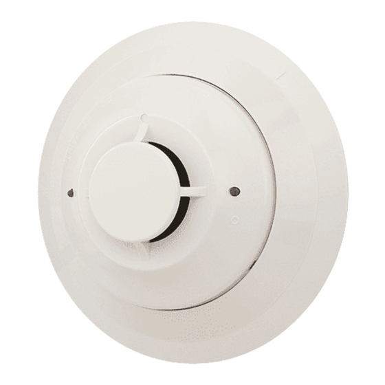
1151 Low Profile Ionization
Plug-in Smoke Detectors
Specifications
Size
Height:
Diameter:
Weight:
Operating Temperature Range:
Operating Humidity Range:
Latching Alarm:
Before Installing
Please thoroughly read the System Sensor manual A05-
1003, Applications Guide for System Smoke Detectors,
which provides detailed information on detector spacing,
placement, zoning, wiring, and special applications. Copies
of this manual are available from System Sensor.
NOTICE: This manual should be left with the owner/user
of this equipment.
IMPORTANT: The detector used with this base must be
tested and maintained regularly following NFPA 72 require-
ments. The detector used with this base should be cleaned
at least once a year.
General Description
Model 1151 ionization detector uses state-of-the-art sens-
ing chambers. This detector is designed to provide open
area protection, and to be used with compatible UL-listed
control panels only. The capability of plugging this detector
into a variety of special bases makes it more versatile than
equivalent direct-wired models.
Two LEDs on each detector light to provide a local 360° vis-
ible alarm indication. Remote LED annunciator capability
is available as an optional accessory. This detector also has
the latching alarm feature. The alarm can be reset only by
a momentary power interruption. For testing, this detector
has an internal magnetically activated reed switch.
Spacing
Spacing of 30 ft. on a smooth ceiling as per NFPA 72.
Where conditions or response requirements vary, other
spacing may apply.
D100-51-00
1.7 inches (43 mm)
4.0 inches (102 mm)
3.6 oz (102 g)
–10°C to 60°C (14°F to 140°F)
NOTE: Do not install in locations where normal ambient temperature range extends
beyond 0°C to 49°C (32°F to 120°F)
10% to 93% Relative Humidity, Noncondensing
Reset by momentary power interruption
1
3825 Ohio Avenue, St. Charles, Illinois 60174
Base Selection and Wiring Guide
Refer to the installation instructions for the plug-in detector
bases for wiring instructions. System Sensor has available a
variety of detector bases for this smoke detector, including
2-wire applications with and without relays and/or current
limiting resistors, 4-wire and 120 VAC applications.
All bases are provided with screw terminals for power,
ground, remote annunciator connections, and relay contact
connections, if applicable. The electrical ratings for each
detector-base combination are also included in the base
installation instructions.
Installation
NOTE: All wiring must conform to applicable local codes,
ordinances, and regulations.
NOTE: Verify that all detector bases are installed, that the
initiating-device circuits have been tested, and that
the wiring is correct.
Remove power from initiating device circuits before install-
ing detectors.
1. Install Detectors:
a. Place the detector into the detector base.
b. Rotate the detector clockwise until the detector drops
into place.
c. Continue rotating the detector clockwise to lock it in
place.
2. Tamper-Resistance: The detector bases include a feature
that, when activated, prevents removal of the detector
without the use of a tool. See the installation instruc-
tion manual of the detector base for details in using this
feature.
1-800-SENSOR2, FAX: 630-377-6495
www.systemsensor.com
WARNING
I56-546-07R
Advertisement
Table of Contents

Related Manuals for System Sensor 1151


Summary of Contents for System Sensor 1151
- Page 1 Please thoroughly read the System Sensor manual A05- Refer to the installation instructions for the plug-in detector bases for wiring instructions. System Sensor has available a 1003, Applications Guide for System Smoke Detectors, variety of detector bases for this smoke detector, including...
- Page 2 Gemini 501 manual. Use the not completely prevent airborne dust particles from enter- bowl shaped applicator to apply aerosol to the sensor. It ing the detector. Therefore, System Sensor recommends the should alarm within 30 seconds. removal of detectors before beginning construction or other dust producing activity.
- Page 3 7. Reinstall the sensor cover. Use the test module socket and LEDs to align the cover with the sensor. Snap the cover into place. 8. When all sensors have been cleaned, restore power to the system and test the sensor(s) as described in the TESTING section of this manual.
- Page 4 Please include a note describing the malfunction and suspected cause period of three years from date of manufacture. System Sensor makes no of failure. The Company shall not be obligated to repair or replace units other express warranty for this smoke detector.
Need help?
Do you have a question about the 1151 and is the answer not in the manual?
Questions and answers