
Related Manuals for Sokkia SET 550


Summary of Contents for Sokkia SET 550
- Page 1 Total Station Setup and Total Station Setup and Operation Operation Sokkia SET Total Station Sokkia SET Total Station...
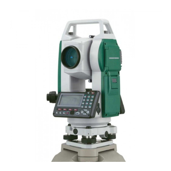
- Page 2 Parts of the SET Total Station Parts of the SET Total Station...
- Page 3 Parts of the SET Total Station Parts of the SET Total Station...
- Page 4 Sokkia SET 550 Total Station Sokkia SET 550 Total Station Keys/Screen Keys/Screen...
- Page 5 SET 550 SET 550 Menu Pages Menu Pages...
- Page 6 SET 550 SET 550 Menu Menu Pages Pages...
- Page 7 Leveling the Total Station Leveling the Total Station Leveling the Total Station must be Leveling the Total Station must be accomplished to sufficient accuracy otherwise accomplished to sufficient accuracy otherwise the instrument will not report results the instrument will not report results Leveling the instrument takes 30 to 45 minutes Leveling the instrument takes 30 to 45 minutes –...
- Page 8 Step 1: Tripod Setup Step 1: Tripod Setup Tripod legs Tripod legs should be should be equally spaced equally spaced Tripod head Tripod head should be should be approximately approximately level level Head should Head should be directly be directly over survey over survey point...
- Page 9 Step 2: Mount Instrument on Tripod Step 2: Mount Instrument on Tripod Place Instrument Place Instrument on Tripod on Tripod Secure with Secure with centering screw centering screw while bracing the while bracing the instrument with instrument with the other hand the other hand Insert battery in Insert battery in...
- Page 10 Step 3: Focus on Survey Point Step 3: Focus on Survey Point Focus the optical Focus the optical plummet on the plummet on the survey point survey point...
- Page 11 Step 4: Leveling the Instrument Step 4: Leveling the Instrument Adjust the leveling foot screws to center the Adjust the leveling foot screws to center the survey point in the optical plummet reticle survey point in the optical plummet reticle Center the bubble in the circular level by Center the bubble in the circular level by adjusting the tripod legs...
- Page 12 Step 4: Leveling … Step 4: Leveling … Loosen the horizontal clamp and turn instrument until Loosen the horizontal clamp and turn instrument until plate level is parallel to 2 of the leveling foot screws plate level is parallel to 2 of the leveling foot screws Center the bubble using the leveling screws Center the bubble using the leveling screws bubble moves toward the screw that is turned...
- Page 13 Step 4: Leveling … Step 4: Leveling … Observe the survey point in the optical Observe the survey point in the optical plummet and center the point by loosening the plummet and center the point by loosening the centering screw and sliding the entire centering screw and sliding the entire instrument instrument...
- Page 14 Step 5: Electronically Verify Step 5: Electronically Verify Leveling Leveling Turn on the instrument by Turn on the instrument by pressing and holding the “ ” pressing and holding the “ ” button (you should hear an button (you should hear an audible beep) audible beep) The opening screen will be the...
- Page 15 Step 5: Adjust Image & Reticle Step 5: Adjust Image & Reticle Focus Focus Release the horizontal & vertical clamps Release the horizontal & vertical clamps and point telescope to a featureless light and point telescope to a featureless light background background Adjust the...
- Page 16 Measuring the Height of An Object Measuring the Height of An Object Level the instrument at a site where the target can be viewed th rough the Level the instrument at a site where the target can be viewed th rough the telescope and the mirror target can be setup directly below the target...
- Page 17 Measurement of Target Height Measurement of Target Height Set the Target Height from “ MEAS ” > “ Menu ” > Set the Target Height from “ MEAS ” > “ Menu ” > “ Coordinate ” > “ Station Orientation ”...
- Page 18 REM Screen Results REM Screen Results To re shoot the To re shoot the mirror target use the mirror target use the [OBS] on the REM [OBS] on the REM screen screen...
- Page 19 Calibrating the Instrument Calibrating the Instrument Calibration must be completed before coordinates can Calibration must be completed before coordinates can be obtained be obtained 3 possible calibrations: 3 possible calibrations: Backsight by angle: must know instrument coordinates and Backsight by angle: must know instrument coordinates and have a landmark/target at a known azimuth have a landmark/target at a known azimuth Backsight...
- Page 20 3D Coordinates 3D Coordinates Coordinates may be absolute or relative depending on Coordinates may be absolute or relative depending on survey requirements survey requirements Surveying the area of a mining site would require Surveying the area of a mining site would require relative coordinates, therefore, the initial instrument relative coordinates, therefore, the initial instrument X,Y,Z coordinates may be 5000, 5000, 100...
- Page 21 Calibrate by Backsight by Angle Calibrate by Backsight by Angle Remember that when the instrument is Remember that when the instrument is powered on it has a random X,Y coordinate powered on it has a random X,Y coordinate system: you must align the instrument with system: you must align the instrument with your working coordinate system.
- Page 22 Backsight by Angle continued.. Backsight by Angle continued.. Measure the target height and Measure the target height and instrument height instrument height Select [COORD] from the MEAS menu Select [COORD] from the MEAS menu Select “ . Orientation ” and then “...
- Page 23 Backsight by Angle continued … Backsight by Angle continued … Select “ Backsight ” and then Select “ Backsight ” and then “ Angle ” from the menu “ Angle ” from the menu Sight the landmark/target of known Sight the landmark/target of known azimuth relative to instrument with azimuth relative to instrument with telescope...
- Page 24 Backsight by Angle Continued … Backsight by Angle Continued … NOTE: because the backsight by angle simply NOTE: because the backsight by angle simply sets the instrument horizontal angle encoder to sets the instrument horizontal angle encoder to match your desired coordinate system the match your desired coordinate system the mirror target is never “...
- Page 25 Backsight by Angle cont … Backsight by Angle cont … Because there is no internal statistical measure Because there is no internal statistical measure of how well the backsight angle has been set it of how well the backsight angle has been set it is imperative to check the backsight is imperative to check the...
- Page 26 Backsight by Coordinate Backsight by Coordinate Use this method when you have 2 Use this method when you have 2 known survey points with the known survey points with the instrument established on one and the instrument established on one and the mirror target on the other survey point mirror target on the other survey point From the...
- Page 27 Backsight by coordinate … Backsight by coordinate … Always check the calibration of the instrument Always check the calibration of the instrument by shooting the target used for the backsight by shooting the target used for the backsight The resulting X,Y,Z should be within the The resulting X,Y,Z should be within the several cm resolution typical for a TS several cm resolution typical for a TS...
- Page 28 Resection Resection Resection uses 3 or more Resection uses 3 or more known target survey points known target survey points to automatically determine to automatically determine the X,Y,Z coordinates of the the X,Y,Z coordinates of the instrument instrument This has the significant This has the significant advantage of not requiring advantage of not requiring...
- Page 29 Resection continued … Resection continued … Prior to resection enter survey markers as known Prior to resection enter survey markers as known points through the “ ” menu points through the “ ” menu From the “ MEAS ” menu select “...
- Page 30 Resection continued … Resection continued … The [MEAS] screen (right) The [MEAS] screen (right) displays the point being shot – displays the point being shot – this example the 1 point this example the 1 point Choose [DIST] if you are Choose [DIST] if you are shooting to a mirror target, shooting to a mirror target,...
- Page 31 Resection continued … Resection continued … Press [CALC] or [YES] on last point to Press [CALC] or [YES] on last point to display the calculated instrument display the calculated instrument coordinates and the standard deviation of coordinates and the standard deviation of Press Press easting (...
- Page 32 Resection Notes Resection Notes Resection initializes the X,Y,Z coordinates of the Resection initializes the X,Y,Z coordinates of the instrument. Save this as a point (ex. G1S02 for group instrument. Save this as a point (ex. G1S02 for group 2, instrument station #2) since it represents a 2, instrument station #2) since it represents a surveyed coordinate surveyed coordinate...
- Page 33 Resection Notes Resection Notes Certain Certain Geometries Geometries should be should be avoided … avoided …...
Need help?
Do you have a question about the SET 550 and is the answer not in the manual?
Questions and answers
How can you use the instrumentos to do insitute check on Beacons...