
Related Manuals for Sokkia im-101


Summary of Contents for Sokkia im-101
- Page 1 SURVEYING INSTRUMENTS iM-100 series intelligence Measurement Station Class 3R Laser Product OPERATOR'S MANUAL 1019174-01-A...
- Page 2 HOW TO READ THIS MANUAL Thank you for selecting the iM-100 series. • Please read this Operator’s manual carefully, before using this product. • iM has a function to output data to a connected host computer. Command operations from a host computer can also be performed.
- Page 3 • Measurement procedures are based on continuous measurement. Some information about procedures when other measurement options are selected can be found in “Note” (). • KODAK is a registered trademark of Eastman Kodak Company. ® • Bluetooth is a registered trademark of Bluetooth SIG, Inc. •...
-
Page 4: Table Of Contents
CONTENTS 1. PRECAUTIONS FOR SAFE OPERATION ..............1 2. PRECAUTIONS ......................4 3. LASER SAFETY INFORMATION .................. 7 4. PRODUCT OUTLINE ....................9 Parts of the Instrument ..................9 Mode Structure ....................12 Bluetooth Wireless Technology/Wireless LAN ........... 13 5. BASIC OPERATION ....................15 Basic Key Operation ................... - Page 5 18.1 Defining Baseline ....................79 18.2 Point Projection ....................79 19. TOPOGRAPHY OBSERVATION ................81 19.1 Observation Setting .................... 82 19.2 Observation ......................83 20. OFFSET MEASUREMENT ..................86 20.1 Single-distance Offset Measurement ..............86 20.2 Angle Offset Measurement ................. 87 20.3 Two-distance Offset Measurement ..............
- Page 6 32.2 Selecting T type/S type ..................174 32.3 Storing JOB Data to USB flash drive ..............174 32.4 Loading Data in USB flash drive to the iM ............176 32.5 Displaying and Editing Files ................177 32.6 Formatting the Selected External Memory Media ..........178 33.
-
Page 7: Precautions For Safe Operation
1. PRECAUTIONS FOR SAFE OPERATION For the safe use of the product and prevention of injury to operators and other persons as well as prevention of property damage, items which should be observed are indicated by an exclamation point within a triangle used with WARNING and CAUTION statements in this operator’s manual. - Page 8 1. PRECAUTIONS FOR SAFE OPERATION Power Supply Warning Do not disassemble or rebuild the battery or the battery charger, nor expose to heavy shocks or vibration. Sparking, fire, electric shock or burns could result. Do not short circuit. Heat or ignition could result. Do not place articles such as clothing on the battery charger while charging batteries.
- Page 9 1. PRECAUTIONS FOR SAFE OPERATION Bluetooth wireless technology/Wireless LAN Warning Do not use within the vicinity of hospitals. Malfunction of medical equipment could result. Use the instrument at a distance of at least 22 cm from anyone with a cardiac pacemaker. ...
-
Page 10: Precautions
2. PRECAUTIONS Charging Battery • Be sure to charge the battery within the charging temperature range. Charging temperature range : 0 to 40°C • Use only the specified battery or the battery charger. Failures caused by using other batteries or battery chargers are out of warranty including the main unit. - Page 11 2. PRECAUTIONS Vertical and horizontal clamps • Always fully release the vertical/horizontal clamps when rotating the instrument or telescope. Rotating with clamp(s) partially applied may adversely affect accuracy. Tribrach • Always use the tribrach provided. During a traverse observation, it is recommended to use the same type of tribrach for the target as well for accurate observations.
-
Page 12: Exceptions From Responsibility
2. PRECAUTIONS • Consult your local dealer before using the instrument under special conditions such as long periods of continuous use or high levels of humidity. In general, special conditions are treated as being outside the scope of the product warranty. Maintenance •... -
Page 13: Laser Safety Information
3. LASER SAFETY INFORMATION The instrument is classified as the following class of Laser Product according to IEC Standard Publication 60825-1 Ed.3.0: 2014 and United States Government Code of Federal Regulation FDA CDRH 21CFR Part 1040.10 and 1040.11 (Complies with FDA performance standards for laser products except for deviations pursuant to Laser Notice No.50, dated June 24, 2007.) Device Laser class... - Page 14 3. LASER SAFETY INFORMATION Caution • Perform checks at start of work and periodic checks and adjustments with the laser beam emitted under normal conditions. • When the instrument is not being used, turn OFF the power and replace the lens cap. •...
-
Page 15: Product Outline
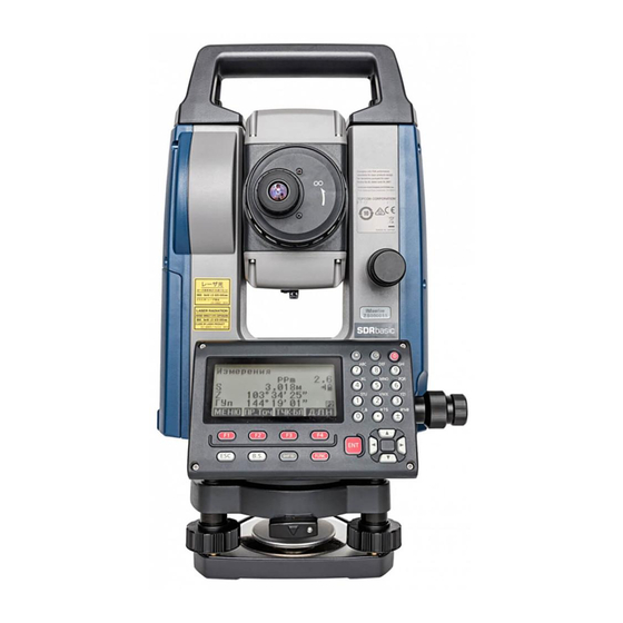
4. PRODUCT OUTLINE Parts of the Instrument Parts and functions of the instrument Handle Instrument height mark Battery cover Operation panel Serial connector Circular level Circular level adjusting screws Base plate Levelling foot screw 10 Optical plummet focussing ring 11 Optical plummet eyepiece (10,11: Not included in instruments with laser plummet) 12 Display unit 13 Guide light... - Page 16 4. PRODUCT OUTLINE Instrument height mark The height of the instrument is as follows: • 192.5 mm (from tribrach mounting surface to this mark) • 236 mm (from tribrach plate to this mark) "Instrument height" is input when setting instrument station data and is the height from the surveying point (where the instrument is mounted) to this mark.
- Page 17 4. PRODUCT OUTLINE Detaching/attaching the Handle The carrying handle can be removed from the instrument when the prism is located at the zenith etc. 1. To remove it, loosen the handle rocking screws. 2. To attache the handle, position the handle as shown, tighten the 2 handle rocking screws securely. Handle Handle rocking screws Detaching the instrument from the tribrach...
-
Page 18: Mode Structure
4. PRODUCT OUTLINE Mode Structure The diagram below describes the different modes of the instrument and key operations for navigating between them. Star key Mode Dist+Coord Note L a s e r p l u m : O f f View L a s e r l e v. -
Page 19: Bluetooth Wireless Technology/Wireless Lan
4. PRODUCT OUTLINE Bluetooth Wireless Technology/Wireless LAN • Bluetooth/Wireless LAN function may not be built in depending on telecommunications regulations of the country or the area where the instrument is purchased. Contact your local dealer for the details. • Use of this technology must be authorized according to telecommunications regulations of the country where the instrument is being used. - Page 20 4. PRODUCT OUTLINE Refrain from using the iM in proximity to televisions and radios. • Televisions and radios use a different frequency band to Bluetooth/Wireless LAN communications. However, even if the iM is used within proximity to the above equipment with no adverse effects with regard to Bluetooth/Wireless LAN communication, moving a Bluetooth/Wireless LAN compatible device (including the iM) closer to said equipment may result in electronic noise in sound or images, adversely affecting the performance of televisions and radios.
-
Page 21: Basic Operation
5. BASIC OPERATION Learn basic key operations here before you read each measurement procedure. Basic Key Operation Starkey Illumination key Power key Display unit Softkey selection Power ON/OFF "8. POWER ON/OFF" Lighting up the reticle/keys Switches the reticle illumination and key light On/Off Switching to Starkey mode ... - Page 22 5. BASIC OPERATION Softkey operation Softkeys are displayed on the bottom line of the screen. Select the function matching the softkeys {F1} to {F4} Toggle between OBS mode screen pages (when more than 4 softkeys {FUNC} are allocated) Inputting letters/figures ...
- Page 23 5. BASIC OPERATION Selecting options Move the cursor up/down Move the cursor/selection item left/right or select other option {}/{} Accepts the option {ENT} Example: Select a reflector type 1. Press [EDM] in page 2 of OBS mode. 2.
-
Page 24: Display Functions
5. BASIC OPERATION Display Functions Status screen Instrument name iM-103 rec 49999 S/N XX123456 Application Ver. X.XXXX_XX software X.XXX version Job.JOB1 DATA CNFG iM-103 rec 49999 S/N XX123456 Date Date Jan/01/2017 Time 12:00:00 Time DATA CNFG iM-103 rec 49999 S/N XX123456 Internal Pt. - Page 25 5. BASIC OPERATION • "TSshield" and "Cloud OAF" may not be installed depending on the model or TSshield/Cloud OAF model may not be available depending on the country or the area where the instrument is purchased. (1) Distance SD: Slope distance HD: Horizontal distance VD: Height difference Switching distance display status: "33.1 Observation Conditions - Angle/Tilt"...
-
Page 26: Starkey Mode
5. BASIC OPERATION (7) Laser-pointer/Guide light display Selecting Laser-pointer/Guide light: "33.7 Instrument Conditions - Instrument", Switching Laser-pointer/ Guide light ON/OFF: "5.1 Basic Key Operation" :Laser-pointer is selected and ON :Guide light is selected and ON (8) Bluetooth communication status :Connection established (flashing): Connecting (flashing): Waiting... -
Page 27: Using The Battery
6. USING THE BATTERY Battery Charging Be sure to charge the battery fully before using it for the first time or after not using it for long periods. • The charger will become rather hot during use. This is normal. •... -
Page 28: Installing/Removing The Battery
6. USING THE BATTERY • Slots 1 and 2: The charger starts charging the battery mounted first. If you place two batteries in the charger, the battery in slot 1 is charged first, and then the battery in slot 2. ( step 2) •... -
Page 29: Setting Up The Instrument
7. SETTING UP THE INSTRUMENT • Mount the battery in the instrument before performing this operation because the instrument will tilt slightly if the battery is mounted after levelling. Centering PROCEDURE Centering with the optical plummet eyepiece 1. Make sure the legs are spaced at equal intervals and the head is approximately level. -
Page 30: Levelling
7. SETTING UP THE INSTRUMENT PROCEDURE Centering with the laser plummet eyepiece Laser plummet is available as a factory option depending on the country or the area where the instrument is purchased. 1. Set up the tripod and affix the instrument on the tripod head. ... - Page 31 7. SETTING UP THE INSTRUMENT 2. Roughly center the bubble in the circular level by either shortening the tripod leg closest to the offcenter direction of Tripod legs adjustment the bubble or by lengthening the tripod leg farthest from the offcenter direction of the bubble.
-
Page 32: Power On/Off
8. POWER ON/OFF • When the power cannot be switched ON or the power is soon turned OFF even though the battery is mounted, there may be almost no battery power remaining. Replace it with a fully charged battery. ... - Page 33 8. POWER ON/OFF PROCEDURE Power OFF 1. Press and hold (about 1 sec) the power key on the operation panel. • When there is almost no battery power remaining, the battery icon in the Status icon will start to blink.In this event, stop measurement, switch off the power and charge the battery or replace with a fully charged battery.
-
Page 34: Connecting To External Devices
9. CONNECTING TO EXTERNAL DEVICES The instrument supports Bluetooth wireless technology and RS232C for communication with data collectors etc. Inputting/outputting data is possible by inserting a USB flash drive or by connecting to a USB device. Read this manual in conjunction with the operator’s manual for the relevant external device. ... - Page 35 9. CONNECTING TO EXTERNAL DEVICES 5. Select "S-Type". Comms setup T t ype S t ype • "T-Type" is for an instrument using GTS commands. 6. Perform communication settings for S-type. Check sum : Items set and options (*: Factory setting) (1) Check sum : Yes/No* ...
-
Page 36: Communication Between The Im And Companion Device
9. CONNECTING TO EXTERNAL DEVICES CR, LF Select the option Off or On for carrige return (CR) and line feed when collecting measurement data with a computer. ACK mode When communicating to an external device, the protocol for handshaking can omit the [ACK] coming from the external device, so data is not sent again. - Page 37 9. CONNECTING TO EXTERNAL DEVICES 2. Check that the iM is in waiting status (Bluetooth symbol is (flashing)) and start communication by the data collector. Manual of the program mounted on the data collector The Bluetooth icon: "5.2 Display Functions" HA-R •...
-
Page 38: Connection Via Rs232C Cable
9. CONNECTING TO EXTERNAL DEVICES Connection via RS232C Cable RS232C communication is possible, connecting instrument and a data collector with the cable. PROCEDURE Basic cable settings 1. Power OFF the instrument and connect the instrument and a data collector with a interface cable. ... -
Page 39: Target Sighting And Measurement
10.TARGET SIGHTING AND MEASUREMENT 10.1 Manually Sighting the Target • When sighting the target, strong light shining directly into the objective lens may cause the instrument to malfunction. Protect the objective lens from direct light by attaching the lens hood. Observe to the same point of the reticle when the telescope face is changed. -
Page 40: Angle Measurement
11.ANGLE MEASUREMENT This section explains the procedures for basic angle measurement in Observation mode. 11.1 Measuring the Horizontal Angle between Two Points (Horizontal Angle 0°) Use the “0SET” function to measure the included angle between two points. The horizontal angle can be set to 0 at any direction. -
Page 41: Setting The Horizontal Angle To A Required Value (Horizontal Angle Hold)
11. ANGLE MEASUREMENT 11.2 Setting the Horizontal Angle to a Required Value (Horizontal Angle Hold) You can reset the horizontal angle to a required value and use this value to find the horizontal angle of a new target. PROCEDURE Entering the horizontal angle 1. - Page 42 11. ANGLE MEASUREMENT 2. Set the known point coordinate. Enter the coordinate for the S E T H a n g l e / B S first point, and press [OK]. N B S : 1 0 0 . 0 0 0 E B S : 1 0 0 .
-
Page 43: Angle Measurement And Outputting The Data
11. ANGLE MEASUREMENT 11.3 Angle Measurement and Outputting the Data The following explains angle measurement and the features used to output measurement data to a computer or peripheral equipment. Bluetooth communication: "10. TARGET SIGHTING AND MEASUREMENT" Communication cables: "39. ACCESSORIES" Output format and command operations: "Communication manual"... -
Page 44: Distance Measurement
12.DISTANCE MEASUREMENT Perform the following settings as preparation for distance measurement. • Distance measurement mode • Target type • Prism constant correction value • Atmospheric correction factor • EDM ALC "33.1 Observation Conditions - Angle/Tilt"/"33.2 Observation Conditions - Dist" Caution •... -
Page 45: Distance And Angle Measurement
12. DISTANCE MEASUREMENT 3. Press [S-LEV]. <Aiming> is displayed. The intensity of the light of the returned signal is displayed by a gauge. MEAS • The more displayed, the greater the quantity of reflected light. • If “*” is displayed, only enough light for the measurement is returned. -
Page 46: Recalling The Measured Data
12. DISTANCE MEASUREMENT • Each time [SHV] is pressed, SD (Slope distance), HD (Horizontal distance) and VD (Height difference) are displayed alternately. MEAS 0SET COORD • Audio tones differ depending on the target type; prism or others. • If the single measurement mode is selected, measurement automatically stops after a single measurement. •... -
Page 47: Coordinate Measurement And Outputting The Data
12. DISTANCE MEASUREMENT PROCEDURE 1. Connect iM and host computer. 2. Allocate the [HVDOUT-T] or [HVDOUT-S] softkey to the OBS mode screen. "33.12 Allocating Key Functions" • Pressing the softkey outputs data in the following format. [HVDOUT-T]: GTS format [HVDOUT-S]: SET format 3. -
Page 48: Rem Measurement
12. DISTANCE MEASUREMENT 5. Press [STOP] to stop outputting data and return to OBS mode. 12.6 REM Measurement An REM measurement is a function used to measure the height to a point where a target cannot be directly installed such as power lines, overhead cables and bridges, etc. The height of the target is calculated using the following formula. - Page 49 12. DISTANCE MEASUREMENT 3. In the second page of OBS mode screen, press [MENU], then select "REM". Area calc. S-O Line S-O Arc P-Project PT to line 4. Enter into the REM menu. Select "REM." Occ.Orien. 5. Sight the target. Pressing [REM] starts REM measurement.
-
Page 50: Coordinate Measurement
13.COORDINATE MEASUREMENT It is possible to set from the instrument station data to the backsight angle in a series of procedures. Setting Instrument Station Data • Key input "13.1 Entering Instrument Station Data and Azimuth Angle" Step 3 • Reading the registered coordinate "13.1 Entering Instrument Station Data and Azimuth Angle"... - Page 51 13. COORDINATE MEASUREMENT 3. Select “Occ.orien.”. Coord. Input the following data items. Occ. Orien. (1) Instrument station coordinates (Occupied point Observation coordinates) (2) Point name (PT) (3) Instrument height (HI) (4) Code (CD) 0.000 (5) Operator 0.000 (6) Date <Null> AUTO100000 (7) Time 1.200m...
- Page 52 13. COORDINATE MEASUREMENT • Humidity range (%): 0 to 100 • The "Humid. (Humidity)" is displayed only when the "Humid.inp" is set to "Yes". • Above-described input ranges are the ranges when 1 mm is selected in "Dist.reso". When 0.1 mm is selected, values can be input to the first decimal place.
- Page 53 13. COORDINATE MEASUREMENT 2. Enter search criteria. 1 0 0 Enter following items. C r i t e r i a : C o m p l e t e (1) Coordinate point name D i r e c t . : (2) Search condition (complete match) (3) Search direction 3.
- Page 54 13. COORDINATE MEASUREMENT 2. Press [BS NEZ] after entering the instrument station data to Backsight enter a backsight point coordinate. 100.000 NBS: 100.000 EBS: • When you wish to read in the registered coordinate data, ZBS: <Null> press [LOAD]. LOAD ""13.1 Entering Instrument Station Data and Azimuth Angle"...
-
Page 55: Setting Instrument Station Coordinate With Resection Measurement
13. COORDINATE MEASUREMENT 13.2 Setting Instrument Station Coordinate with resection measurement Resection is used to determine the coordinates of an instrument station by performing multiple measurements of points whose coordinate values are known. Registered coordinate data can be recalled and set as known point data. - Page 56 13. COORDINATE MEASUREMENT 3. Select "Setting". Resection. Elevation Setting 4. Set for resection measurement. Setting Set the following items: F1/F2 Obs (1) RL observation (F1/F2 Obs): : On Observe every point in Face 1 and 2 in resection. " 13.2.3 RL observation in resection measurement" Set "F1/F2 Obs"...
- Page 57 13. COORDINATE MEASUREMENT 13.2.2 Coordinate Resection Measurement Observe existing points with known coordinate data to calculate the coordinate value for the instrument station. • Between 2 and 10 known points can be measured by distance measurement, and between 3 and 10 known points by angle measurement.
- Page 58 13. COORDINATE MEASUREMENT 7. Repeat procedures 4 to 6 in the same way from the second point. When the minimum quantity of observation data required for the calculation is present, [CALC] is displayed. 8. Press [CALC] to automatically start calculations after 3rd P T observations of all known points are completed.
- Page 59 13. COORDINATE MEASUREMENT Pressing [OK] sets the direction angle and instrument 100.001 station data, and then returns to <Coord.>. 100.009 9.999 PNT-001 1.200m LOAD • Pressing [REC] displays the backsight point recording screen. Press [OK] to the following data. Instrument station data, backsight station data, known point HA-R 1 2 0 data, and angle measurement data (distance measurement...
- Page 60 13. COORDINATE MEASUREMENT 5. Press [Yes] to use the measurement results of the first Resection 1st R known point in Face 1. 525.450m • You can input target height here. HA-R 1 2 0 1.400m 6. Measure the first known point in Face 2. Resection 1st L "L"...
- Page 61 13. COORDINATE MEASUREMENT 13.2.4 Height Resection Measurement Only Z (height) of an instrument station is determined by the measurement. • Known points must be measured by distance measurement only. • Between 1 and 10 known points can be measured. PROCEDURE 1.
- Page 62 13. COORDINATE MEASUREMENT 10.If there are problems with the results of a point, align the cursor with that point and press [OMIT]. “*” is displayed on - 0 . 0 0 3 1 s t the left of the point. - 0 .
- Page 63 13. COORDINATE MEASUREMENT Precaution when performing resection • Instrument station may not be calculated when the included angles between the known points and the station point are too narrow. Especially when the instrument station and the known points are far away, it is difficult to know that the included angles between the known points are narrow.
-
Page 64: Coordinate Measurement
14.COORDINATE MEASUREMENT By performing coordinate measurements it is possible to find the 3-dimensional coordinates of the target based on station point coordinates, instrument height, target height, and azimuth angles of the backsight station which are entered in advance. • EDM setting can be done in coordinate measurement menu. Setting items: "33.2 Observation Conditions - Dist"... - Page 65 14. COORDINATE MEASUREMENT 2. In the third page of OBS mode screen, press [MENU], then select "Coordinate". 3. Select "Occ.orien." to set the instrument station data and Coord. azimuth angle of the backsight point. Occ.Orien. Observation 4. In <Coord>, select "Observation". Pressing [MEAS] will Coord.
-
Page 66: Setting-Out Measurement
15.SETTING-OUT MEASUREMENT Setting-out measurement is used to set out the required point. The difference between the previously input data to the instrument (the setting-out data) and the measured value can be displayed by measuring the horizontal angle, distance or coordinates of the sighted point. The horizontal angle difference and distance difference are calculated and displayed using the following formulae. - Page 67 15. SETTING-OUT MEASUREMENT 1. Press [S-O] on the third page of the OBS mode screen to display <S-O>. 2. Select "Occ.orien." to set the instrument station data and azimuth angle of the backsight point. "13.1 Entering Instrument Station Data and Azimuth Angle PROCEDURE Reading in Registered Coordinate Data"...
-
Page 68: Distance Setting-Out Measurement
15. SETTING-OUT MEASUREMENT 8. Move the prism forward and backward until the setting-out distance is 0 m. If S-OΔHD is “+”, move the prism toward yourself, if it is “-”, move the prism away from yourself. • By pressing [← →], an arrow pointing to the left or right Back displays which direction the target should be moved. - Page 69 15. SETTING-OUT MEASUREMENT 3. Select “S-O data.” 4. Press [DISP] to change the distance input mode to <S-O S-O HD H>. • Each time [DISP] is pressed: S-O Coord (coordinates), S- H d i s t : 0 . 0 0 0 O HD (horizontal distance), S-O SD (slope distance), S-O H a n g : VD (height difference), S-O Ht.
-
Page 70: Rem Setting-Out Measurement
15. SETTING-OUT MEASUREMENT 10.Press {ESC} to return to <S-O>. • When [LOAD] was used in step 4, the list of registered coordinates is restored. Continue setting-out measurement. • [REC]: records measurement results Recording method: "28. RECORDING DATA - TOPO MENU -" 15.3 REM Setting-out Measurement To find a point where a target cannot be directly installed, perform REM setting-out measurement. -
Page 71: Setting-Out Line
16.SETTING-OUT LINE Setting-out line is used for setting out a required point at a designated distance from the baseline and for finding the distance from the baseline to a measured point. 2nd Pt. Fill Grade 1st Pt. Baseline Offset Length Azimuth 16.1 Defining Baseline To perform setting-out line measurement, first, define the baseline. - Page 72 16. SETTING-OUT LINE 4. Enter the first point data and press [OK]. D e f i n e 1 s t P T 1 1 3 . 4 6 4 N p : • When [LOAD] is pressed, registered coordinates can be 9 1 .
- Page 73 16. SETTING-OUT LINE 12.Press [OK] on the screen of step 11 to define the baseline. S e t - o u t l i n e <Set-out line> is displayed. Move to setting-line P o i n t measurement. L i n e "16.2 Setting-out Line Point"/"16.3 Setting-out Line Line"...
-
Page 74: Setting-Out Line Point
16. SETTING-OUT LINE • Scale factor settings can be set in the screen shown at A z m t h 93 20 right. 13. 003m H c a l c 17. 294m H m e a s 1. 000091 S c a l e X S c a l e Y 1. - Page 75 16. SETTING-OUT LINE 2. Set the following items. S e t - o u t l i n e (1) Incr: Increment by which line length and offset can be I n c r 1 . 0 0 0 m decreased/increased using the arrow softkeys.
-
Page 76: Setting-Out Line Line
16. SETTING-OUT LINE 2. Press [OFFSET] to display <Baseline offset>. S e t - o u t l i n e I n c r 1 . 0 0 0 m 0 . 0 0 0 L i n e 0 . - Page 77 16. SETTING-OUT LINE 1. Select “Line” in <Set-out line>. S e t - o u t l i n e P o i n t L i n e 2. Enter the offset value. S e t - o u t l i n e •...
-
Page 78: Setting-Out Arc
17.SETTING-OUT ARC This mode allows the operator to define an arc from various arc parameters, such as From Pt. coordinates, and set out this arc as well as points (offsets) along it. Tangent length Intersection To Pt. Direction Radius Offset Angle From Pt. - Page 79 17. SETTING-OUT ARC 4. Enter the arc From point data and press [OK]. 5. Press {}/{} to select coordinates then press [OK]. S e l e c t P t . : Enter arc To point. To/Center : Enter arc To point and Center point. To/Intersect : Enter arc To point and Intersect point (intersection of the tangents).
- Page 80 17. SETTING-OUT ARC • It is also possible to perform setting-out arc measurement by pressing [S-O ARC] when allocated to the OBS mode screen. Allocating [S-O ARC]: "33.12 Allocating Key Functions" PROCEDURE Defining by observation 1. In the second page of OBS mode screen, press [MENU], then select "Set-out arc".
- Page 81 17. SETTING-OUT ARC 9. Enter other arc parameters. D i r e c t i o n : L e f t (1) Direction (whether the arc turns right/left from the From R a d i u s : < N u l l > point) <...
- Page 82 17. SETTING-OUT ARC Specifying points and curve parameters Parameters that can be entered may be restricted depending on the points specified in step 5/6. Parameters that can be entered are marked with a circle ( ○ ). Those that cannot are marked with a cross ( × ). Parameters Radius Angle...
-
Page 83: Setting-Out Arc
17. SETTING-OUT ARC 17.2 Setting-out Arc Setting-out arc measurement can be used to find the coordinates of required points along the arc by inputting the arc (or chord) length and offset based on the arc. Offset Chord • Before performing setting-out arc, the arc must be defined. PROCEDURE 1. - Page 84 17. SETTING-OUT ARC PROCEDUREOffsetting the arcline The arcline can be offset in three dimensions using four methods: lateral offset, rotation angle offset, lengthwise offset, and height offset. Rotation Lateral offset angle offset Lengthwise offset Height offset 1. Select “Set-out arc” in <Set-out arc>. 2.
-
Page 85: Point Projection
18.POINT PROJECTION Point projection is used for projecting a point onto the baseline. The point to project can be either measured or input. Displays the distances from the first point and point to project to the position at which a line extending from point to project intersects the baseline at right angles. - Page 86 18. POINT PROJECTION 2. Select "Point Projection" in <Point Projection>. Point projection Stn. Orien. Define baseline Point projection 3. Enter the point coordinate. P o i n t p r o j e c t i o n 1 0 3 . 5 1 4 N p : •...
-
Page 87: Topography Observation
19.TOPOGRAPHY OBSERVATION In topography observation, the instrument observes each target point once, clockwise from the backsight direction and record the observed data. It is also possible to conduct topography RL observation which observes the target point once from each of the "Right" and the "Left" of the scope. Target point Topography observation T1 (backsight direction) -
Page 88: Observation Setting
19. TOPOGRAPHY OBSERVATION 19.1 Observation Setting Perform observation setting prior to topography observation. • Up to 40 collimation points can be registered. • It is possible to register up to 8 combination patterns for the number of distance sets, the number of distance readings, Yes or No for RL observation, pre-entered point registration, backsight distance measurement and backsight distance check. -
Page 89: Observation
19. TOPOGRAPHY OBSERVATION 5. Enter backsight point coordinates. Topography Enter the coordinates for the backsight point and press [OK]. BS coord If "No" is set for (5) Backsight distance measurement (BS 0.000 NBS: 0.000 Obs-Dist) or (6) Backsight distance check (BS DistCheck) in EBS: PT AUTO1000 the observation setting, this screen is not displayed. - Page 90 19. TOPOGRAPHY OBSERVATION 2. Measure the first direction. Topography Collimate the first target. Press [ANGLE] or [MEAS] to start measuring. In "D=", the setting value for the Number of HA-R distance readings (No. of Obs) is displayed. 0.000m AUTO0011 ANGLE MEAS •...
- Page 91 19. TOPOGRAPHY OBSERVATION 2. Measure the target point in the R direction. Topography "R" appears next to the "Topography observation (Topography)" HA-R “PROCEDURE Topography Observation” step 2 0.000m AUTO0011 ANGLE MEAS 3. Record the measured data. “PROCEDURE Topography Observation” step 3 4.
-
Page 92: Offset Measurement
20.OFFSET MEASUREMENT Offset measurements are performed in order to find a point where a target cannot be installed directly or to find the distance and angle to a point which cannot be sighted. • It is possible to find the distance and angle to a point you wish to measure (target point) by installing the target at a location (offset point) a little distance from the target point and measuring the distance and angle from the survey point to the offset point. -
Page 93: Angle Offset Measurement
20. OFFSET MEASUREMENT 6. Input the following items. (1) Horizontal distance from the target point to the offset point. (2) Direction of the offset point. • Direction of offset point ← : On the left of the target point. → : On the right of the target point. ↓... -
Page 94: Two-Distance Offset Measurement
20. OFFSET MEASUREMENT PROCEDURE 1. Set the offset points close to the target point (making sure the distance from the instrument station to the target point and the height of the offset points and the target point are the same), then use the offset points as the target. 2. - Page 95 20. OFFSET MEASUREMENT • It is possible to make this measurement easily using the optional equipment: the 2-point target (2RT500-K). When using this 2-point target, be sure to set prism constant to 0. "7.2 Levelling" How to use 2-point target (2RT500-K) •...
-
Page 96: Plane Offset Measurement
20. OFFSET MEASUREMENT 6. Sight the 2nd target and press [MEAS]. The measurement results are displayed. Press [YES]. Confirm? 7. Enter the distance from the 2nd target to the target point and press {ENT}. The coordinates of the target point are displayed. - Page 97 20. OFFSET MEASUREMENT 2. Press [OFFSET] in page three of OBS mode to display <Offset>. 3. Select “Offset Plan” in <Offset>. Offset Occ.Orien. OffsetDist OffsetAng. Offset2D Offset Plan 4. Sight the first point (P1) on the plane and press [MEAS] to begin measurement.
-
Page 98: Column Offset Measurement
20. OFFSET MEASUREMENT 20.5 Column Offset Measurement Find distance and coordinates of the center of the column. If circumscription point (P1) and two circumscription points (P2, P3) of a column can be measured directly, the distance to the center of the column (P0), coordinates and azimuth angle are calculated and displayed. •... - Page 99 20. OFFSET MEASUREMENT 6. Sight the right circumscription point (P3) and press [OK]. HA-R M e a s . R i g h t P t . O K ? 7. The coordinates of the target point (the center of the column O ffs et C l um P0) are displayed.
-
Page 100: Missing Line Measurement
21.MISSING LINE MEASUREMENT Missing line measurement is used to measure the slope distance, horizontal distance, and horizontal angle to a target from the target which is the reference (starting point) without moving the instrument. • It is possible to change the last measured point to the next starting position. •... - Page 101 21. MISSING LINE MEASUREMENT The following values are displayed: SD: Slope distance of the starting position and 2nd target. 20.757m HD: Horizontal distance of the starting position and 2nd 27.345m 1.012m position. VD: Height difference of the starting position and 2nd target. MOVE MEAS •...
- Page 102 21. MISSING LINE MEASUREMENT • When [MOVE] is pressed, the last target measured becomes the new starting position to perform missing line measurement of the next target. "21.2 Changing the Starting Point" 5. Press {ESC} to end missing line measurement. PROCEDURE Calculating from input coordinates 1.
-
Page 103: Changing The Starting Point
21. MISSING LINE MEASUREMENT • When [S/%] is pressed, the distance between two points (S) is displayed as the gradient between two points. • Press [MEAS] to observe the starting position. "PROCEDURE Measuring using observation" • When [MOVE] is pressed, the last target measured becomes the new starting position to perform missing line measurement of the next target. - Page 104 21. MISSING LINE MEASUREMENT 3. The last target measured is changed to the new starting position. Perform missing line measurement. "21.1 Measuring the Distance between 2 or more Points".
-
Page 105: Surface Area Calculation
22.SURFACE AREA CALCULATION You can calculate the area of land (slope area and horizontal area) enclosed by three or more known points on a line by inputting the coordinates of the points. Input Output Coordinates : P1 (N1, E1, Z1) Surface area: S (slope area and horizontal area) P5 (N5, E5, Z5) •... - Page 106 22. SURFACE AREA CALCULATION 4. Sight the first point on the line enclosing the area, and press [OBS]. • The tilt screen is displayed if the instrument is out of level. Level the instrument. LOAD "7.2 Levelling" 12.345 5. Press [MEAS] to begin observation. 137.186 The measured values are displayed.
- Page 107 22. SURFACE AREA CALCULATION 4. Press [LOAD] to display the list of coordinate data. Pt_01 :Known point date saved in the current JOB or in the Coordinate Search JOB. Crd./ Occ :Coordinate data saved in the current JOB or in the Coordinate Search JOB.
-
Page 108: Intersections
23.INTERSECTIONS The following two types of intersection calculation are available. Select a suitable intersection type in advance. Selecting an intersection type: "33.5 Observation Conditions - Other" Type A Selectable calculation methods are as follows. • 1 pt, Azimuth • Extend "23.1.1 1 pt, Azimuth"... - Page 109 23. INTERSECTIONS • Intersections survey screens contain the [REC] and [S-O] softkeys. 1pt, Azi m uth 345. 678 -876.543 R E C S - O • Press [REC] to record measurement results as a known point in the JOB. r e c 3 0 0 0 3 4 5 .
- Page 110 23. INTERSECTIONS 4. Input azimuth angle and distance from known point, then 2:A zi m ut h press [OK]. Coordinates for the target point are displayed. 0. 0000 3: D i st 0. 000m 5. Press [OK] to return to the screen in step 3 and continue 1pt, A zi m uth measurement as necessary.
- Page 111 23. INTERSECTIONS 5. Input horizontal angle and distance from instrument station, 3:A ngl e then press [OK]. Coordinates for the target point are 0. 0000 displayed. 4: D i st 0. 000m 6. Press [OK] to return to the screen in step 3 and continue 2pt , Angl e measurement as necessary.
- Page 112 23. INTERSECTIONS 4. Input coordinates for the second, third, and fourth points ("Line A-2", "Line B-1", and "Line B-2"). step 3 5. Press [OK] to return to the screen in step 3 and continue 4 p t measurement as necessary. 345.678 -876.543 •...
- Page 113 23. INTERSECTIONS 4. Input radius for the first circle "R1" and press [OK]. 2: R 1 100. 000 5. Input coordinates for the second center point and radius for the second circle ("Center2" and "R2"). steps 3 to 4 6.
- Page 114 23. INTERSECTIONS 4. Input coordinates for the second point. step 3 5. Input distance from the first point to the target point and 3: D i st press [OK]. 280.000 6. Press [OK] to return to the screen in step 3 and continue E xtend measurement as necessary.
- Page 115 23. INTERSECTIONS 5. Input the number of segments you wish to divide the 3: D i vi de distance into and press [OK]. 6. Coordinates for each dividing point are displayed on D i vi de consecutive screens. To switch between result screens, 345.678 press {}/{}.
-
Page 116: Intersections (Type B)
23. INTERSECTIONS 5. Input pitch and press [OK]. 3: Pi t ch 30. 000 6. Coordinates for each calculated point are displayed on Pi t ch consecutive screens. To switch between result screens, 345. 678 press {}/{}. -876. 543 Press [OK] to return to the screen in step 3 and continue 2/ 5 measurement as necessary. - Page 117 23. INTERSECTIONS PROCEDURE 1. In the second page of the OBS mode screen, press Intersect. [MENU], then select "Intersect.". Traverse Road Xsection 2. Enter the 1st point data and press [NEXT]. D e f i n e 1 s t P T 1 1 3 .
- Page 118 23. INTERSECTIONS 5. Press [OK]. The coordinate value of the intersection point is 4 5 0 0 ’ 0 0 " A z m t h 1 calculated and displayed. H . d i s t 1 < N u l l > <...
-
Page 119: Traverse Adjustment
24.TRAVERSE ADJUSTMENT Measurement of a traverse begins with observation of the backsight station and foresight station. The instrument station is then moved to the foresight station and the previous instrument station becomes the backsight station. Observation is performed again at the new position. This process is repeated for the length of the route. - Page 120 24. TRAVERSE ADJUSTMENT • Enter values manually when there are no coordinates Occ: saved for the specified instrument station. Press [OK] to proceed to step 4. <Null> PT T-0001 LOAD 4. Enter the point name of the backsight station for the start T r a v e r s e s t a r t p t .
- Page 121 24. TRAVERSE ADJUSTMENT 7. Enter the point name of the backsight station for the end T r a v e r s e e n d p t . point and press {ENT}. The calculated azimuth angle is displayed. Occ: T - 0 0 0 1 F s : T - 0 0 0 2...
- Page 122 24. TRAVERSE ADJUSTMENT Allocating [TRAV]: "33.12 Allocating Key Functions" • Traverse adjustment results of traverse points, points observed from traverse points and traverse adjustment data will be saved in the currently selected JOB as Notes data. Data including the distributed closure error will also be saved in the currently selected JOB as ordinary coordinate data.
- Page 123 24. TRAVERSE ADJUSTMENT The automatic route search function cannot be used in the following case. • The final measurement is to a traverse point on the traverse route other than the Start pt. Adjustment methods Adjustment is applied to results for traverse points and points observed from traverse points. Adjustment methods and distribution options selected in step 8 are described below.
-
Page 124: Route Surveying
25.ROUTE SURVEYING This mode allows a variety of route surveying options widely used in civil engineering measurement. Each menu allows the operator to initiate a string of successive configuration/calculation/record/setting-out operations. • The orientation of the instrument station and backsight station can be set as necessary. For backsight station settings, see"13.1 Entering Instrument Station Data and Azimuth Angle". -
Page 125: Straight Line Calculation
25. ROUTE SURVEYING 25.2 Straight Line Calculation The coordinates of the center peg and width pegs for a straight line can be found from the coordinates of the reference point and IP point. It is then possible to proceed with the setting-out of the center peg and width pegs. Reference point (P1) IP point (P2) Follow-up distance (DL) - Page 126 25. ROUTE SURVEYING 4. Input the coordinates of the IP point, then press [OK]. L i n e / I P N p : 2 0 0 . 0 0 0 • The azimuth angle to the IP point can be set by pressing E p : 2 0 0 .
-
Page 127: Circular Curve Calculation
25. ROUTE SURVEYING 25.3 Circular Curve Calculation The coordinates of the center peg and width pegs on a circular curve can be found from the coordinates of the BC point and IP point. It is then possible to proceed with the setting-out of the center peg and width pegs. BC point (P1) IP point (P2) Circular curve radius (R) -
Page 128: Spiral Curve
25. ROUTE SURVEYING 7. Press {ESC} twice to finish Circular Curve calculation and return to <Road>. • Press [WIDTH] to move to the width peg setting screen. "25.2 Straight Line Calculation" • The center peg can be set-out by pressing [S-O] ... - Page 129 25. ROUTE SURVEYING Calculation using KE2 as reference: "KE KA Calculation" KE point (P1) KE tangential angle (AZ) Clothoid parameter A KE-KA KE to KA curve length (L) Curve length KE follow-up distance (DL1) Target point follow-pu distance (DL2) Route width (BL) Q Stationing Chainage Stationing Chainage...
- Page 130 25. ROUTE SURVEYING 5. Enter the curve direction, parameter A, offset, and follow-up S p i r a l / C L p e g distance. D i r e c t . R i g h t P a r a A 8 0 .
- Page 131 25. ROUTE SURVEYING 5. Enter the curve direction, parameter A, KA-P curve length S p i r a l / C L p e g (length of curve from KA to P point), offset, and P-target D i r e c t . R i g h t curve length (length of curve from P point to target point).
- Page 132 25. ROUTE SURVEYING 5. Enter the curve direction, parameter A (clothoid parameter), S p i r a l / C L p e g KE-KA curve length (length of curve from KE to KA), KE D i r e c t . R i g h t follow-up distance, and target point follow-up distance.
-
Page 133: Parabola
25. ROUTE SURVEYING 25.5 Parabola The coordinates of the center peg and width pegs on a parabola can be found from the coordinates of the reference point and curve properties. It is then possible to proceed with the setting-out of the center peg and width pegs •... - Page 134 25. ROUTE SURVEYING PROCEDURE Calculation using BTC Point as reference 1. In the second page of the OBS mode screen, press [MENU], then select "Road". 2. Select "Parabola" to enter the Parabola menu then select Road "BTCBCC Calc." O c c . O r i e n . L i n e C i r c .
- Page 135 25. ROUTE SURVEYING 7. Press {ESC} three times to finish Parabola calculation and return to <Road>. • Press [WIDTH] to move to the width peg setting screen. "25.2 Straight Line Calculation" • The center peg can be set-out by pressing [CENTER]. ...
-
Page 136: Point Calculation
25. ROUTE SURVEYING 6. Press [OK] in the screen shown in step 5 to calculate the P a r a b o l a / C L p e g center peg coordinates. The coordinates are then displayed 4 7 5 0 9 0 . 3 1 1 in this screen. - Page 137 25. ROUTE SURVEYING 3. Input the coordinates of the BP point (reference point). 3 P T C u r v e / B P Press [OK] to set the input values. 1 0 0 . 0 0 0 N p : E p : 1 0 0 .
-
Page 138: Intersection Angle/Azimuth Angle Calculation
25. ROUTE SURVEYING 9. In the screens for the KA1 point, KE1 point, KE2 point, and 3 P T C u r v e / C L p e g KA point that have been found, press [CENTER] to move to centerline peg settings. - Page 139 25. ROUTE SURVEYING 2. Select "IP&Tan" to enter the intersection angle/azimuth 3 P T C u r v e angle calculation menu. I P & Ta n A l i g n m e n t E D M 3. Input the coordinates of the BP point (reference point). I A &...
-
Page 140: Route Calculation
25. ROUTE SURVEYING 7. In the screens for the KA1 point, KE1 point, KE2 point, and I A & Ta n g e n t / C L p e g KE2 point that have been found, press [CENTER] to move to centerline peg settings. - Page 141 25. ROUTE SURVEYING Deleting a JOB: "29.2 Deleting a JOB" Memory initialization: ""33.13 Restoring Default Settings" PROCEDURE Restoring set items to initial settings and turning power on" • Curve data is not set when curve properties (parameter A1, parameter A2, radius R) are all set to "Null". •...
- Page 142 25. ROUTE SURVEYING 8. Check the EP. Check the coordinate for the EP, and press [OK]. 2 0 0 . 0 0 0 N p : E p : 4 0 0 . 0 0 0 9. Quit inputting the IPs. <C urv e number:2>...
- Page 143 25. ROUTE SURVEYING 3. Input the elements for the curve 1. E l e m e n t 1 Input the parameter A1, parameter A2, radius R, and offset P a r a A 1 5 0 . 0 0 0 (additional distance for the BP: if the BP is located before the P a r a A 2 5 0 .
- Page 144 25. ROUTE SURVEYING 3. Align the cursor with "Review elements" and press {ENT}. Define elements Use {}/{} to move through property screens in the I n p u t I P following order: BP Point -> IP Point -> EP Point -> curve I n p u t e l e m e n t properties ->...
- Page 145 25. ROUTE SURVEYING 25.8.5 Automatic calculation of cardinal points Perform automatic calculation of cardinal points based on the curve properties set in “25.8.2 Inputting Curve Elements”. Center pegs (peg No.) and width pegs set up at intervals can be calculated at once. •...
- Page 146 25. ROUTE SURVEYING 5. Press [OK] in the screen shown in step 4 to calculate the Results coordinates of the cardinal point, width pegs and peg No. 1 0 0 . 0 0 0 The coordinates are then displayed on the screens shown 1 0 0 .
- Page 147 25. ROUTE SURVEYING route widths (route width from the center peg to the LEFT width peg). When both route widths are input as positive (+) "R" and "R2" are used. When both route widths are input as negative (-) "L" and "L2" are used.
- Page 148 25. ROUTE SURVEYING 25.8.7 Inverse width peg The route widths and coordinates for center pegs on every calculated curve can be found by using inverse width peg calculation. • There are two methods for specifying arbitrary width peg coordinates: key entry and observation. PROCEDURE Using key entry to specify arbitrary width pegs 1.
- Page 149 25. ROUTE SURVEYING 2. Sight the width peg and press [MEAS] to start A l i g n m e n t / R o a d t o p o measurement. The coordinates and measurement distance 0 . 0 0 0 N p : of the width peg, vertical angle and horizontal angle are ...
- Page 150 25. ROUTE SURVEYING 3. Select "Setting" to enter the Setting Parameters menu. A l i g n m e n t D e f i n e e l e m e n t s A u t o c a l c . C a l c c o o r d R o a d t o p o S e t t i n g...
-
Page 151: Cross Section Survey
26.CROSS SECTION SURVEY The purpose of this function is to measure and set out points along a cross-section of a road or linear feature already surveyed using the route surveying function. Cross-sections can be surveyed in a variety of directions depending on your requirements. - Page 152 26. CROSS SECTION SURVEY 4. Input road name for cross section survey, station pitch, X s e c t i o n S u r v e y station increment, stationing chainage and select direction. R o a d n a m e : Then press [OK].
- Page 153 26. CROSS SECTION SURVEY Enter center point name. Then press [OK]. 3 + 3 . 2 0 0 C e n t e r : N o . 3 + 3 . 2 0 0 F i n i s h e d s e c t i o n : LOAD •...
- Page 154 26. CROSS SECTION SURVEY Direction of route Pattern 1 Pattern 2 Pattern 3 Right side observed Left side observed with a second prism with one prism When "Right" or "Left -> Right" selected Pattern 1: From right-most point to left-most point. Pattern 2: Center point observed first.
-
Page 155: Point To Line Measurement
27.POINT TO LINE MEASUREMENT Point to line allows an operator to define the coordinates of the target point when a line connecting the base point A (0, 0, 0) and the point B is set as the X axis. The instrument's station coordinates and angle for an unknown point C is set by observing the point A and the point B. - Page 156 27. Point to Line MEASUREMENT 5. Measure the second target point in the same manner as the Measure 2nd PT first one. HA-R 1 7 8 2.000m 1004 MEAS Confirm the measured result and press [OK]. 5.123m HA-R 1 7 8 2.000m 1004 MEAS...
- Page 157 27. Point to Line MEASUREMENT • Pressing [REC] records the coordinates of the target point 20.000 as measured data in the current JOB. 30.000 40.000 2.500m • Pressing [S.CO] displays the coordinates of the instrument 1001 station. S.CO MEAS 4. Collimate the next target point and press [MEAS] to begin measurement.
-
Page 158: Recording Data - Topo Menu
28.RECORDING DATA - TOPO MENU - In Record menu, you can store the measurement data (distance, angle, coordinates), station point data, backsight station data, and note in the current JOB. "29. SELECTING/DELETING A JOB" • A total of 50,000 data can be stored inside the instrument. Recording instrument station data and backsight station data is an exception. - Page 159 28. RECORDING DATA - TOPO MENU - 3. Set the following data items. (1) Instrument station coordinates (2) Point name (3) Instrument height (4) Code LOAD (5) Operator (6) Date (Display only) (7) Time (Display only) (8) Weather (9) Wind (10) Temperature LIST SRCH...
-
Page 160: Recording Backsight Point
28. RECORDING DATA - TOPO MENU - 28.2 Recording Backsight Point Backsight station data can be stored in the current JOB. Azimuth angle setting method can be selected from “inputting azimuth angle” or “calculating coordinates”. PROCEDURE Inputting azimuth angle 1. Press [TOPO] in the third page of OBS mode to display <TOPO>. -
Page 161: Recording Angle Measurement Data
28. RECORDING DATA - TOPO MENU - 4. Input the backsight station coordinates. TOPO / Backsight NBS : 1.000 • When you wish to read in and set coordinate data from EBS : 1.000 memory, press [LOAD]. ZBS : <Null> ... -
Page 162: Recording Distance Measurement Data
28. RECORDING DATA - TOPO MENU - 3. Set the following items. (1) Target height (2) Point name HA-R (3) Code 1 0 1 0 R E C TILT H-SET 0SET A D D L I S T S R C H 4. -
Page 163: Recording Coordinate Data
28. RECORDING DATA - TOPO MENU - 5. To continue measurement, sight the next point, press [MEAS], then perform steps 3 and 4 above. HA-R MEAS OFFSET AUTO • Press [AUTO] to perform distance measurement and automatically record the results. [AUTO] is convenient for recording measurement data when target height, code and point name are not set. -
Page 164: Recording Distance And Coordinate Data
28. RECORDING DATA - TOPO MENU - 4. Check the input data, then press [REC]. 5. To continue measurement, sight the next point, press [MEAS], then perform steps 3 and 4 above. • Pressing [AUTO] will start measurement, and automatically record the measured results. It is convenient to record measured data without setting the collimation height, code and point name. -
Page 165: Reviewing Job Data
28. RECORDING DATA - TOPO MENU - 28.7 Recording Notes This procedure prepares notes data and records it in the current JOB. PROCEDURE 1. Press [TOPO] in the third page of OBS mode to display Dist + Coord <TOPO>. Note Select “Note”. - Page 166 28. RECORDING DATA - TOPO MENU - 2. Select the point name to be displayed in detail and press 1 2 3 . 4 5 6 m [ENT]. 2 0 3 1 2 1 Details of the data are displayed. This screen contains HA-R 11 7 3 2 2 1...
-
Page 167: Deleting Recorded Job Data
28. RECORDING DATA - TOPO MENU - 28.9 Deleting Recorded JOB Data It is possible to delete data from the currently selected JOB. • Deleting each data does not free the memory. When a JOB is deleted, the occupied memory is freed. "29.2 Deleting a JOB"... -
Page 168: Selecting/Deleting A Job
29.SELECTING/DELETING A JOB 29.1 Selecting a JOB Select the current JOB and Coordinate Search JOB. • A total of 99 JOBs have been prepared, and JOB1 was selected when your iM was shipped from the factory. • The names of the JOBs have been preset as JOB1 to JOB99; you can change them to any names you wish. •... -
Page 169: Deleting A Job
29. SELECTING/DELETING A JOB 4. Align the cursor with the desired JOB as the current JOB and press {ENT}. The JOB is determined. 5. Press {ENT}. <JOB selection> is restored. 6. Align the cursor with “Coord search JOB” and press [LIST]. <Coord search JOB>... - Page 170 29. SELECTING/DELETING A JOB 2. Select “JOB deletion”. <JOB deletion> is displayed. JOB selection JOB details JOB deletion • The numbers to the right represent the number of data Comms output items in each JOB. Comms setup 3. Align the cursor with the desired JOB and press {ENT}. 4.
-
Page 171: Registering/Deleting Data
30.REGISTERING/DELETING DATA 30.1 Registering/Deleting Known Point Data It is possible to register or delete coordinate data of the known points in the current JOB. The coordinate data that has been registered can be output during setting for use as instrument station, backsight station, known point, and setting-out point coordinate data. - Page 172 30. REGISTERING/DELETING DATA PROCEDURE Entering known point coordinate data from an external instrument 1. Connect iM and host computer. 2. Select “Known data” in Data Mode. 3. Select “Comms input” to display <Comms input>. Known data Job.JOB1 Key in coord Comms input Deletion View...
- Page 173 30. REGISTERING/DELETING DATA 2. Select “Deletion” to display the list of known point data. Known data Job.JOB1 Key in coord Comms input Deletion View POINT01 ABCDEF 123456789 FIRST LAST SRCH 3. Select the point name to be deleted and press {ENT}. •...
-
Page 174: Registering/Deleting Codes
30. REGISTERING/DELETING DATA 30.2 Reviewing Known Point Data It is possible to display all the coordinate data within the current JOB. PROCEDURE 1. Select “Known data” in Data Mode. • Current JOB name is displayed. 2. Select “View”. Known data The point name list is displayed. - Page 175 30. REGISTERING/DELETING DATA 2. Select “Key in code”. Code Enter the code and press {ENT}. The code is registered and Key in code <Code> is restored. Comms input Comms output Deletion Code view • Maximum code size: 16 (alphanumeric) •...
-
Page 176: Reviewing Codes
30. REGISTERING/DELETING DATA 3. Align the cursor with the code to be deleted and press [DEL]. The designated code is deleted. FIRST 4. Press {ESC} to restore <Code>. • If you select “Clear list” in step 2 and then press [YES], all registered codes are deleted. 30.4 Reviewing Codes PROCEDURE 1. -
Page 177: Outputting Job Data
31.OUTPUTTING JOB DATA It is possible to output JOB data to a host computer. Communication cables: "39. ACCESSORIES" Output format and command operations: "Communication manual" • Measurement results, instrument station data, known point data, notes, and coordinate data in the JOB is output. - Page 178 31. OUTPUTTING JOB DATA 7. Select the output format and press {ENT}. When T type is selected GTS(Obs) GTS(Coord) SSS(Obs) SSS(Coord) When S type is selected SDR2X When "GTS (Obs)" or "SSS (Obs)" is selected, select the output format of distance data. Obs data •...
-
Page 179: Using Usb Flash Drive
32.USING USB FLASH DRIVE It is possible to read in/output data from/to a USB flash drive. • When using a USB flash drive, data is stored in the root directory. You cannot read/write data from/to subdirectories. • When using the iM, an MS-DOS-compatible text file can be input/output. ... -
Page 180: Selecting T Type/S Type
32. USING USB FLASH DRIVE • When using a USB memory with 4 metal terminals on the surface, insert it with the terminal facing backwards to avoid damaging the USB port. 3. Close the cover. Listen for the click to ensure that the cover is properly closed. 32.2 Selecting T type/S type 1. - Page 181 32. USING USB FLASH DRIVE 4. Select output format. Save data (When T type is selected ) GTS(Obs) GTS(Coord) SSS(Obs) SSS(Coord) Save data Obs data Reduced data 5. Enter the file name. Press {ENT} to set the data. JOB01. raw : Jan/01/2017 Date •...
-
Page 182: Loading Data In Usb Flash Drive To The Im
32. USING USB FLASH DRIVE 1. Select "Save code" on the first page of the USB mode. Save data Load known PT Save code Load code File status 2. Specify a file name and press {ENT}. COD01. TXT Entering extension name: " PROCEDURE Data saving Date : Jan/01/2017 step5"... -
Page 183: Displaying And Editing Files
32. USING USB FLASH DRIVE 4. In the list of files, select the file to be read in and press ABCDE {ENT}. FGHI JKLMNOPQ 5. Press [YES] to read in the file on the iM. <Media> is ABCDE restored. 5354byte Jan/01/2017 17:02 To cancel reading, press {ESC}. -
Page 184: Formatting The Selected External Memory Media
32. USING USB FLASH DRIVE 2. In the list of the files stored in the external memory media, ABCDE select a file to be displayed and press {ENT}. Details of the FGHI file are displayed. JKLMNOPQ ABCDE 5354byte Jan/01/2017 17:02 Format :SDR33 3.4GB / 3.8GB Remaining memory / Total memory size... -
Page 185: Changing The Settings
: Zenith*, Horiz, Horiz 90° (Horizontal ±90°) Ofs V ang : Hold*, Free Ang.reso.(Angle resolution) : iM-101: 0.5", 1"* iM-102/103/105: 1", 5"* Automatic tilt angle compensation mechanism The vertical and horizontal angles are automatically compensated for small tilt errors using the 2-axis tilt sensor. -
Page 186: Observation Conditions - Dist
33. CHANGING THE SETTINGS V obs. (vertical angle display method) Zenith Horiz Horiz 90° Ofs V ang Select whether the vertical angle is fixed in the angle offset measurement. 33.2 Observation Conditions - Dist Select "Obs.condition" in Config mode and select "Dist". M o d e F i n e ”... - Page 187 33. CHANGING THE SETTINGS • "Road" in "Mode (Distance measurement Mode)" is displayed only when "N-Prism" is selected in <Reflector>. "33.3 Observation Conditions - Reflector (Target)" Road "Road" is the specialized distance mode to measure road surface etc. by sighting obliquely and to obtain rough measurement values.
-
Page 188: Observation Conditions - Reflector (Target)
33. CHANGING THE SETTINGS Dist.reso. (Distance resolution) Select distance resolution of fine measurement. Distance resolution of rapid and tracking measurement will shift with this setting. Tracking reso. (Tracking resolution) Select distance resolution of tracking measurement and road measurement (N-prism only). Set this setting depending on the measurement purpose like measuring a moving target. -
Page 189: Observation Conditions - Atmosphere
33. CHANGING THE SETTINGS • Press [EDM] in Observation mode to display <EDM> and to perform target and atmospheric condition settings. Illum.hold: Laser 33.4 Observation Conditions - Atmosphere Select "Obs.condition" in Config mode and select "Atmos". Obs.condition Te m p . An g le/Tilt P r e s . -
Page 190: Observation Conditions - Other
33. CHANGING THE SETTINGS t: Air temperature (°C) p: Pressure (hPa) e: Water vapor pressure (hPa) h: Relative humidity (%) E : Saturated water vapor pressure • e (water vapor pressure) can be calculated using the following formula × --------- - ×... -
Page 191: Instrument Conditions - Power
33. CHANGING THE SETTINGS Items set and options (*: Factory setting) Input order : PT CODE*/CODE PT Stn.ID Incr. (station ID increment) : 0 to 99999 (100*) Intersection : Type A/Type B* Input order The input order of point name and code in recording screens can be selected. ... -
Page 192: Instrument Conditions - Instrument
33. CHANGING THE SETTINGS 33.7 Instrument Conditions - Instrument Select "Inst. Config" in Config mode and select "Instrument". Instr.config Contrast Power supply Illum.hold : Laser Instrument Guide light Unit Guide pattern : 1 Password V manual : No Date and time Reticle lev Volume Items set and options (*: Factory setting) -
Page 193: Instrument Conditions - Unit
33. CHANGING THE SETTINGS 33.8 Instrument Conditions - Unit Select "Inst. Config" in Config mode and select "Unit". Instr.config Power supply Instrument Unit Password Date and time Items set and options (*: Factory setting) Temp. (Temperature) ° ° Press : hPa*, mmHg, inchHg Angle : degree*, gon, mil Dist... -
Page 194: Instrument Conditions - Password
33. CHANGING THE SETTINGS 33.9 Instrument Conditions - Password When a password has been set, the password screen will appear when the instrument is powered ON. Setting a password allows you to protect important information such as measurement data. No password is set when the instrument is shipped. When setting a password for the first time, leave the "Old password"... -
Page 195: Tsshield
33. CHANGING THE SETTINGS 33.10 Instrument Conditions - Date and Time Select "Inst. Config" in Config mode and select "Date & Time". Instr.config Date and time Power supply Instrument Date: Jan / 01 / 2017 Unit Time: 16:44:38 Password Date and time Items set Date: Entry example: July 20, 2017... -
Page 196: Allocating Key Functions
33. CHANGING THE SETTINGS 33.12 Allocating Key Functions It is possible to allocate the softkeys in OBS mode to suit the measurement conditions. It is possible to operate the iM efficiently because unique softkey allocations can be preset to suit various applications and the ways that different operators handle the instrument. - Page 197 33. CHANGING THE SETTINGS [TRAV] : Traverse adjustment [ROAD] : Route surveying [X SECT] : Cross section survey [TOPOII] : Topography observation [L-PLUM] : Brightness configuration for laser plummet [HVDOUT-T] / [HVDOUT-S] : Output distance/angle measurement results to an external instrument [HVOUT-T] / [HVOUT-S] : Output angle measurement results to an external instrument [NEZOUT-T] / [NEZOUT-S]...
-
Page 198: Restoring Default Settings
33. CHANGING THE SETTINGS 5. Press [OK] to record the allocations and restore <Key function>. The functions with their new allocations are displayed in OBS mode. PROCEDURE Registering an allocation 1. Allocate functions to the softkeys. “PROCEDURE Allocating functions” 2. Select “Key function” in Config mode. 3. - Page 199 33. CHANGING THE SETTINGS 3. The iM is turned on, “Default set” appears on the screen and all items are restored to their initial settings. PROCEDURE Initializing the data and turning the power on 1. Turn the power off. 2. While pressing {F1}, {F3} and {B.S.}, press the power key. 3.
-
Page 200: Warning And Error Messages
34.WARNING AND ERROR MESSAGES The following is a list of the error messages displayed by the instrument and the meaning of each message. If the same error message is repeated or if any message not shown below appears, the instrument has malfunctioned. - Page 201 34. WARNING AND ERROR MESSAGES Memory is full There is no more room to enter data. Record the data again after deleting unnecessary data from the JOB or coordinate data from the memory. Need 1st obs During missing line measurement, the observation of the starting position was not completed normally. Sight the starting position accurately and press [OBS] to perform the measurement again.
- Page 202 34. WARNING AND ERROR MESSAGES Install the instrument station far from the target. The instrument station coordinates calculated during resection are too high. Perform the observation again. During setting-out line measurement, scale factor has been less than 0.100000 or exceeded 9.999999. During area calculation, results exceeded the display range.
- Page 203 34. WARNING AND ERROR MESSAGES Too short Input password has fewer than 3 characters. Password must have 3 or more characters and 8 or fewer characters. USB error An error has occurred in loading or saving data to USB flash drive. USB full ! There is no more room to enter data on USB flash drive.
-
Page 204: Checks And Adjustments
35.CHECKS AND ADJUSTMENTS A iM is a precision instrument that requires fine adjustments. It must be inspected and adjusted before use so that it always performs accurate measurements. • Always perform checking and adjustment in the proper sequence beginning from "35.1 Circular Level" to "35.7 Laser Plummet *1". - Page 205 35. CHECKS AND ADJUSTMENTS 2. Set the horizontal angle to 0°. Press [0SET] twice in the first page of the OBS mode screen to set the horizontal angle to 0°. 3. Select “Instr. const” in the Config. mode screen to display Config the current correction constant in the X (sighting) direction Obs.condition...
- Page 206 35. CHECKS AND ADJUSTMENTS 9. Rotate the top of the instrument through 180° until the displayed horizontal angle is 180° ±1’ and [OK] is displayed. 10.Wait a few seconds for the display to stabilize, then store the automatically compensated angles X1 and Y1. Press [YES] to store tilt angles X1 and Y1.
-
Page 207: Reticle
35. CHECKS AND ADJUSTMENTS 35.3 Collimation With this option you can measure collimation error in your instrument so that the instrument can correct subsequent single face observations. To measure the error, make angular observations using both faces. • Perform adjustment in weak sunlight and no scintillation. PROCEDURE Adjusting 1. -
Page 208: Optical Plummet
35. CHECKS AND ADJUSTMENTS PROCEDURE Check 2: Vertical and horizontal reticle line positions • Perform check in weak sunlight and no scintillation. • "Tilt crn" should be se to "Yes (H,V)" and "coll.crn" to "Yes" in <Obs. condition> while performing checks. 1. - Page 209 35. CHECKS AND ADJUSTMENTS 2. Turn the upper part through 180° and check the position of the survey point in the reticle. If the surveying point is still centered, no adjustment is necessary. If the survey point is no longer centered in the optical plummet, perform the following adjustment.
-
Page 210: Additive Distance Constant
35. CHECKS AND ADJUSTMENTS 7. Replace the optical plummet reticle cover by matching the grooves on the cover with the grooves on the optical plummet. Groove 35.6 Additive Distance Constant The additive distance constant K of the iM is adjusted to 0 before delivery. Although it almost never deviates, use a baseline with a known distance precision to check that the additive distance constant K is close to 0 several times a year and whenever the values measured by the instrument begin to deviate by a consistent amount. -
Page 211: Laser Plummet
35. CHECKS AND ADJUSTMENTS 35.7 Laser Plummet Checks and adjustments are performed using an adjustment target. Make an enlarged or reduced copy of the figure below. Laser plummet is available as a factory option depending on the country or the area where the instrument is purchased. - Page 212 35. CHECKS AND ADJUSTMENTS 6. When the laser beam is on the upper (lower) part of Fig. A the up/down adjustment is made as follows: (1) Insert the provided hexagon key wrench into both the upper and lower screws. Desired final position Fig.
-
Page 213: Cloud Oaf
36.CLOUD OAF The iM has a function to update option authorization file (OAF) using the Cloud OAF system. The system allows you to customize and configure the instrument according to your purpose. To update Cloud OAF, you need to purchase a specific optional package in advance. Contact your local dealer for the details of the available options and purchasing process. - Page 214 36. CLOUD OAF 4. Insert the USB flash drive to a USB port of the instrument. 5. After confirming that battery level is sufficient, press the power key while holding {SHIFT } and Update starts automatically. Option Update Updating Option... Bluetooth: ON Complete 6.
-
Page 215: Power Supply System
37.POWER SUPPLY SYSTEM Operate your instrument with the following combinations of power equipment. • For details about batteries and chargers, refer to each dedicated manual. • Never use any combination other than those indicated below. If you do, the instrument could be damaged. Those indicated by * are standard accessories. -
Page 216: Target System
38.TARGET SYSTEM Select a prism or a target depending on your purpose. The following are all special accessories (sold separately). • When using a reflecting prism equipped with a target for distance and angle measurements, be sure to direct the reflective prism correctly and sight the center of the prism target accurately. - Page 217 38. TARGET SYSTEM 3. Turn the upper part through 180° and check the bubble position. If the bubble is still centered, no adjustment is necessary. If the bubble is off-center, adjust as follows. 4. Correct half of the bubble displacement using levelling foot screw C. 5.
-
Page 218: Accessories
39.ACCESSORIES The following are outlines and how to use standard accessories (not all) and optional accessories. The following items are explained in other chapters. Power supply and target optional accessories: "37. POWER SUPPLY SYSTEM", "38. TARGET SYSTEM". Plumb bob (optional accessory) ... - Page 219 39. ACCESSORIES Solar filter (OF3A) (optional accessory) During solar observation, attach it to the objective lens of the instrument to protect its interior and the eyes of its operator. The filter part can be flipped up without being removed. Power cable/Interface cable (optional accessory) ...
-
Page 220: Specifications
Rotary absolute encoder Detecting 2 sides IACS (Independent Angle Calibration System) Angle units Degree/Gon/Mil (selectable) Minimum display iM-101: 1" (0.0002 gon/0.005 mil)/0.5" (0.0001 gon/0.002 mil) (selectable) iM-102/103/105: 1" (0.0002 gon/0.005 mil)/5" (0.0010 gon/0.02 mil) (selectable) Accuracy iM-101: 1" (0.0003 gon/0.005 mil) iM-102: 2"... - Page 221 40. SPECIFICATIONS Mini pole prism OR1PA 1.3 to 500 m (1,640 ft) Compact prism CP01 1.3 to 2,500 m (8,200 ft) Standard prism AP01AR X 1 1.3 to 5,000 m (16,400 ft) (1.3 to 6,000 m (19,680 ft)) Reflective sheet RS90N-K 1.3 to 500 m (1,640 ft) *5 *6 1.3 to 300 m (980 ft)
- Page 222 40. SPECIFICATIONS ppm input range: -499.9 to 499.9 ppm (in 0.1 ppm step) Prism constant correction -99.9 to 99.9 mm (in 0.1 mm step) 0 mm fixed for reflectorless measurement Earth curvature and refraction correction No/Yes K=0.142/Yes K=0.20 (selectable) Scale factor setting 0.5 to 2.0 Sea level correction No/Yes (selectable)
- Page 223 40. SPECIFICATIONS Bluetooth profile SPP, DUN Power class Class 1.5 *16 *17 Usable range about 10 m (while in communication with SHC500) *15: Bluetooth function may not be built in depending on telecommunications regulations of the country or the area where the instrument is purchased. Contact your local dealer for the details. *16: No obstacles, few vehicles or sources of radio emissions/interference in the near vicinity of the instrument, no rain.
- Page 224 40. SPECIFICATIONS Charger (CDC68A) Input voltage: 100 to 240 VAC Charging time per battery (at 25°C): BDC70: about 5.5 hours (Charging can take longer than the times stated above when temperatures are either especially high or low.) Charging temperature range: 0 to 40°C Storage temperature range: -20 to 65°C...
-
Page 225: Explanations
41.EXPLANATIONS 41.1 Manually Indexing the Vertical Circle by Face 1/2 Measurement The 0 index of the vertical circle of your instrument is almost 100% accurate, but when it is necessary to perform particularly high precision vertical angle measurements, you can eliminate any inaccuracy of the 0 index as follows. -
Page 226: Correction For Refraction And Earth Curvature
41. EXPLANATIONS 41.2 Correction for Refraction and Earth Curvature The instrument measures distance, taking into account correction for refraction and earth curvature. Distance Calculation Formula Distance Calculation Formula; with correction for refraction and earth curvature taken into account. Follow the Formula below for converting horizontal and vertical distances. -
Page 227: Regulations
42.REGULATIONS Region/ Directives/ Description Country Regulations U.S.A. FCC-Class B FCC Compliance WARNING: Changes or modifications to this unit not expressly approved by the party responsible for compliance could void the user's authority to operate the equipment. NOTE: This equipment has been tested and found to comply with limits for a Class B digital device, pursuant to Part 15 of the FCC Rules. - Page 228 42. REGULATIONS Region/ Directives/ Description Country Regulations California Recycling and NY, Batteries U.S.A. Canada ICES-Class B This class B digital apparatus meets all requirements of Canadian interference-Causing Equipment Regulations. Cet appareil numérique de la class B respecte toutes les exigences du Réglement sur le matérique brouilleur du Canada.
- Page 229 42. REGULATIONS Region/ Directives/ Description Country Regulations EMC-Class B EMC NOTICE In industrial locations or in proximity to industrial power installations, this instrument might be affected by electromagnetic noise. Under such conditions, please test the instrument performance before use. This product complies with the electromagnetic environmental testing of industrial locations.
- Page 230 http://www.topcon.co.jp Please see the attached address list or the following website for contact addresses. GLOBAL GATEWAY http://global.topcon.com/ © 2017 TOPCON CORPORATION ALL RIGHTS RESERVED...
Need help?
Do you have a question about the im-101 and is the answer not in the manual?
Questions and answers