Advertisement
Quick Links
HITEC 2.4GHz
Receiver Instruction
• Risk of explosion exists if battery is replaced by an incorrect type.
Dispose of the used battery according to the instructions.
European CE notice to users and product statements:
This product is CE marked according to the provisions of the R&TTE Directive(99/5/EC).
Hereby, HITEC RCD Inc, declares that this product is in compliance with the essential
requirements and other relevant provisions of Directive 1999/5/EC.
For further information, please contact http://www.hitecrcd.co.kr
FCC notice to users and product statements:
THIS DEVICE COMPLIES WITH PART 15 OF THE FCC RULES.
Operation is subject to the following two conditions: (1) this device may not
cause harmful interference and (2) this device must accept any interference received
including interference that may cause an undesired operation.
CAUTION: Changes or modi cations not expressly approved by the party
responsible for compliance could void the user's authority to operate the equipment.
• FRANCE Frequency Range : 2.4056GHz~ 2.4482GHz
Introduction
Thank you for your purchase of the Hitec Adaptive Frequency Hopping Spread Spectrum (AFHSS) 2.4GHz
module and receiver system. This manual contains the complete directions on how to use the Optima series of
receivers (version 3.00(0). We encourage you to review the entire manual before using these products.
Service & Support
Hitec Customer Service
Help is available from the Hitec o ce through phone support and e-mail inquiries.
Our US o ce is generally open Monday thru Friday, 8:00AM to 4:30PM PST. These hours and days may vary by
season. Every attempt is made to answer every incoming service call. Should you reach our voicemail, leave
your name and number and a sta member will return your call.
Hitec Website
Make plans to visit the Hitec website, www.hitecrcd.com, on a regular basis. Not only is it full of specs and
other information about the entire Hitec product line, our website's FAQ pages will eventually hold valuable
information and program updates about the Spectra 2.4 module and Optima series of receivers.
The On-Line Community
One of the bene ts of the extensive R/C online community is the vast wealth of archived knowledge available.
Hitec sponsors forums on most of the popular R/C websites where a Hitec sta member or representative tries
to answer all manner of product related questions. Bringing together strangers with common interests is
proving to be one of the greatest gifts of the internet. If past history is any guide to the future, we are certain
forums will be started about the Hitec 2.4 system and several are certain to stand out as valuable archives of
information.
Warranty and Non-Warranty Service
All Hitec products carry a two year from date-of-purchase warranty against manufacturer's defects. Our trained
and professional service representatives will determine if the item will be repaired or replaced. To provide all
the necessary information we need to administrate your repair, visit our website at www.hitecrcd.com and
download the repair form, ll it out and send in your item for repair.
Hitec Service
12115 Paine St. Poway CA 92064
1-858-748-6948
E-mail: service@hitecrcd.com
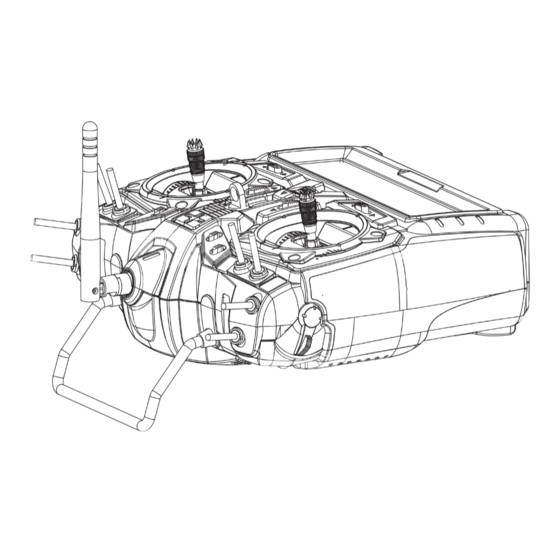
1. For maximum performance, it is recommended to position the antenna at a 90 degree angle as
shown in the picture below.
Recommended Position
version 1.0
2. The receiver antenna should not be placed near the engine, metal parts or high current batteries.
3. When using a large number of high-power digital servos in a model, it is highly recommended to
use the SPC feature to insure the receiver always gets the power it needs in high load conditions.
If not, use the system with enough receiver battery capacity.
4. There could be a possible time delay in receiving telemetry data from the HTS-SS (sensor-station)
depending on the conditions in the area you y.
5. It is strongly recommended that you use Hitec 's genuine Heavy Duty High Channel Switch Harness with
Receiver Charger Cord (Stock#. 54407S) for all of Optima series of receivers.
OPTIMA Series Receiver Speci cations & Features
Full Range AFHSS 2.4GHz Receivers
Receiver Model
MINIMA 6T
1.19 x 0.81 x 0.27in (30.4 x 20.8 x 7.11mm) 0.22oz (6.5g)
MINIMA 6E
1.24 x 0.81 x 0.42in (31.7 x 20.8 x 10.9mm) 0.22oz (6.5g)
OPTIMA 6 LITE 1.76 x 1.11 x 0.29in (44.9 x 18.4 x 7.40mm) 0.33oz (9.4g)
OPTIMA 6
1.81 x 0.82 x 0.47in (46.1 x 21.3 x 12.1mm) 0.52oz (15g)
OPTIMA 7
2.20 x 0.79 x 0.43in (56.9 x 20.8 x 11.6mm) 0.60oz (17g)
OPTIMA 9
1.85 x 1.14 x 0.59in (47.7 x 29.1 x 15.5mm) 0.77oz (22g)
Operating Voltage : 4.8~7.4V From receiver battery power or speed control (ESC) power.
4.8~35V Using SPC function.
Max Current Consumption : 190mA
MINIMA 6T
6
OPTIMA 6
Warning!
Size
Weight
Stock Number
26610
26612
29438
28410
28414
28425
6
OPTIMA 6
MINIMA 6E
LITE
6
6
OPTIMA 7
OPTIMA 9
1. Function Button
- Used for binding the receiver to a module or Hitec 2.4 built-in transmitters,
entering the FAIL-SAFE or Hold feature.
2. Dual LED Status Indicator
- Indicates the set-up process codes and current status of the receiver.
3. Channel Output and Battery Input Ports
- The ports for battery power input and servos, gyros and other accessories output port are located at the
side end of the Optima receivers.
4. SPC (Supplementary Power Connection)*
- Power the Optima receiver function with up to a 35V electric aircraft motor battery.
Details about the SPC system can be found on page 2.
5. Telemetry Sensor and Data Port*
- A three pin servo plug connector port is featured on the Optima 7 and Optima 9 (not applicable on
Optima 6). Using the HPP-22 PC interface accessory, this port serves to facilitate upgrading the device's
software and interfacing the optional onboard sensor station.
6. BODA (Boosted Omni-Directional Antenna) System*
- Hitec's exclusive 2.4GHz BODA System will show you another means of using the 2.4GHz system. This
single antenna with omni-directional booster makes it a whole lot easier to install the 2.4GHz antenna.
Intensive tests have proven that the single BODA system in our 6 & 7 channel systems is better than or equal
to our competitor's dual antenna systems. Our Optima 9 receiver features a dual BODA system to give
the added security that larger models need. Installation is easy and simple, just insert the antenna into the
supported antenna holder and stick it to the desired spot you wish to install.
Compatibility
- The OPTIMA & MINIMA series of receivers are compatible with transmitters using Hitec's AFHSS 2.4 GHz
system such as Spectra 2.4 module or dedicated built-in module AFHSS 2.4 Hitec transmitters.
FAIL-SAFE/Hold Mode Selectable
- The positions of the servos and other accessories can be set with a FAIL-SAFE point, if power to the receiver is
lost. See page 2 for details.
Low Onboard Battery Warning Function
While you are ying, you will know when the on-board battery is low with a warning alarm from the transmitter.
Review the Low Battery alarm features that use direct telemetry feedback to your transmitter on page 2.
Jumper*
The jumper is installed at the factory and is used when the receiver is powered by an electronic speed control,
a commercially available B.E.C. (battery eliminator circuit), dedicated 4.8 to 6V, NiMH battery pack or a
regulated Li-Po battery. The jumper is removed when the receiver is powered using the SPC feature as
described in more detail on page 2.
*These functions/ features are only for the OPTIMA series of receivers.
Receiver Connection Diagrams
-To see a receiver connection diagram for the SPC feature, see page 2.
Note
Electric powered aircraft with Electronic Speed Control
Use this method on electric planes using ESCs providing power to the receiver and servo functions.
OPTIMA
OPTIMA
7
7
CH1
2.4GHz 7 Channel Aircraft Receiver
2.4GHz 7 Channel Aircraft Receiver
CH2
DATA
CH3
LED
LED
SPC
CH4
2.4GHz
BAT/CH7
Telemetric
ADAPTIVE
LINK
LINK
AFHSS
FREQUENCY HOPPING
CH5
CH6
SPREAD SPECTRUM
BEC
ESC
Motor
Power Battery
Power Battery
Glow, gas or electric powered aircraft using a separate receiver battery supply
Follow this connection diagram when using a regulated Li-Po or 4.8 to 6V receiver battery.
OPTIMA
OPTIMA
7
7
CH1
CH2
2.4GHz 7 Channel Aircraft Receiver
2.4GHz 7 Channel Aircraft Receiver
DATA
LED
LED
CH3
SPC
2.4GHz
CH4
BAT/CH7
Telemetric
LINK
LINK
AFHSS
ADAPTIVE
CH5
Engine
CH6
FREQUENCY HOPPING
SPREAD SPECTRUM
Receiver
Battery
2.4GHz 6 Channel
Aircraft Receiver
BEC
ESC
Motor
2.4GHz 6 Channel
Aircraft Receiver
Engine
Receiver
Battery
Advertisement

Related Manuals for HITEC MINIMA 6T


Summary of Contents for HITEC MINIMA 6T
- Page 1 Operating Voltage : 4.8~7.4V From receiver battery power or speed control (ESC) power. Make plans to visit the Hitec website, www.hitecrcd.com, on a regular basis. Not only is it full of specs and -To see a receiver connection diagram for the SPC feature, see page 2.
- Page 2 Release the link button. - Some Hitec servos are rated to be used at 7.4 volts. You will still need to supply power for your servos with a four or five-cell NiMH receiver battery or a 2-cell Li-Po and regulator set-up.
Need help?
Do you have a question about the MINIMA 6T and is the answer not in the manual?
Questions and answers