Table of Contents
Advertisement
For product information,
Owner's Manual translations,
and more, visit
www.MillerWelds.com
™
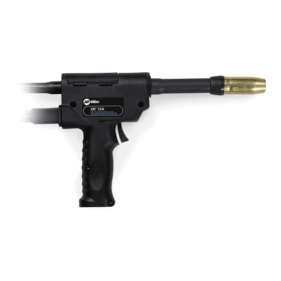
XR A And XR W
(With Quick Disconnect)
200 Ampere (Air) Push-Pull Welding Gun
400 Ampere (Water) Push-Pull Welding Gun
OM-236297P
Processes
Description
™
CE
2016−10
MIG (GMAW) Welding
Semi-Automatic, Air/Water-
Cooled, MIG (GMAW) Welding
Gun
File: MIG (GMAW)
Advertisement
Table of Contents
Troubleshooting

Related Manuals for Miller XR-15A


Summary of Contents for Miller XR-15A
- Page 1 OM-236297P 2016−10 Processes MIG (GMAW) Welding Description Semi-Automatic, Air/Water- Cooled, MIG (GMAW) Welding ™ ™ XR A And XR W (With Quick Disconnect) 200 Ampere (Air) Push-Pull Welding Gun 400 Ampere (Water) Push-Pull Welding Gun For product information, File: MIG (GMAW) Owner’s Manual translations, and more, visit www.MillerWelds.com...
- Page 2 We know you don’t have time to do it any other way. That’s why when Niels Miller first started building arc welders in 1929, he made sure his products offered long-lasting value and superior quality.
-
Page 3: Table Of Contents
TABLE OF CONTENTS SECTION 1 −SAFETY PRECAUTIONS FOR GMAW WELDING GUNS − READ BEFORE USING ..1-1. Symbol Usage ............... . 1-2. - Page 4 DECLARATION OF CONFORMITY for European Community (CE marked) products. MILLER Electric Mfg. Co., 1635 Spencer Street, Appleton, WI 54914 U.S.A. declares that the product(s) identified in this declaration conform to the essential requirements and provisions of the stated Council Directive(s) and Standard(s).
-
Page 5: Section 1 −Safety Precautions For Gmaw Welding Guns − Read Before Using
SECTION 1 −SAFETY PRECAUTIONS FOR GMAW WELDING GUNS − READ BEFORE USING SR7 (MIG) 2015-09 Protect yourself and others from injury — read, follow, and save these important safety precautions and operating instructions. 1-1. Symbol Usage DANGER! − Indicates a hazardous situation which, if Indicates special instructions. -
Page 6: Proposition 65 Warnings
NOISE can damage hearing. READ INSTRUCTIONS. D Read and follow all labels and the Owner’s Noise from some processes or equipment can damage hearing. Manual carefully before installing, operating, or servicing unit. Read the safety information at D Check for noise level limits exceeding those the beginning of the manual and in each specified by OSHA. -
Page 7: Utilisation
SECTION 2 − MESURES DE SÉCURITÉ VISANT LES PISTOLETS DE SOUDAGE GMAW − À LIRE AVANT UTILISATION SR7(MIG)_2015−09 fre Pour écarter les risques de blessure pour vous−même et pour autrui — lire, appliquer et ranger en lieu sûr ces consignes relatives aux précautions de sécurité... -
Page 8: Proposition Californienne 65 Avertissements
LES PIÈCES CHAUDES peuvent LES FILS DE SOUDAGE peuvent provoquer des brûlures. provoquer des blessures. D Laisser refroidir le pistolet avant de le toucher. D Éloigner les mains et le corps de la buse du D Ne pas toucher d’objets métalliques chauds. pistolet après avoir appuyé... -
Page 9: Section 3 − Definitions
SECTION 3 − DEFINITIONS 3-1. Additional Safety Symbols And Definitions Some symbols are found only on CE products. Warning! Watch Out! There are possible hazards as shown by the symbols. Safe1 2012−05 Do not discard product (where applicable) with general waste. Reuse or recycle Waste Electrical and Electronic Equipment (WEEE) by disposing at a designated collection facility. -
Page 10: Section 4 − Specifications
SECTION 4 − SPECIFICATIONS 4-1. Gun Specifications Model Welding Output Range Electrode Wire Feed Net Weight Wire Diameter Speed Range (Torch Only) Capacity XR-A − 15 and 30 ft 200 A at 100% Duty Cycle .030 To 1/16 in. 70 To 900 ipm 2.2 lb (1 kg) (4.6 or 9.1 m) gun 250 A at 60% Duty Cycle... -
Page 11: Section 5 − Installation
SECTION 5 − INSTALLATION Be sure that contact tip, liner, and drive rolls are correct for wire size and type. See Parts List to change parts as needed. 5-1. Connections With A Constant Current (CC), Constant Voltage (CV) Or Constant Current/Constant Voltage (CC/CV) Welding Power Source Having A 14-Socket Receptacle XR D Control... -
Page 12: Air-Cooled Gun Connections
5-2. Air-Cooled Gun Connections Left Side Ref. 245 995-A / 246 218-A / 250 581-A Gun Control Cable Gun Bushing Loosen gun securing knob and insert gun power pin through gun bushing until it Insert plug into Gun Control receptacle, and Gun Securing Knob bottoms against drive casting. -
Page 13: Water-Cooled Gun Connections
5-3. Water-Cooled Gun Connections Turn on coolant supply before welding or gun will be dam- aged. Gun Control Cable Insert plug into Gun Control receptacle, and tighten threaded collar. Gun Power Pin Gun Securing Knob Gun Bushing Drive Casting Loosen gun securing knob, and insert gun power pin through gun bushing until it bottoms against drive casting. -
Page 14: Millermatic 350/350P Water Cooled Gun Connections
5-4. Millermatic 350/350P Water Cooled Gun Connections Tools Needed: Ref. 804 945-A / 151 666-G 9/16 in. Water In Hose bottoms against block. Tighten knob. Close Turn on coolant supply before welding and latch door. or gun will be damaged. Connect to coolant supply with supplied Water Out Hose Coolant Supply... -
Page 15: Threading Welding Wire Through Millermatic 350/350P
5-5. Threading Welding Wire Through Millermatic 350/350P Wire Spool Welding Wire Inlet Wire Guide Drive Roll Intermediate Wire Guide Outlet Wire Guide Pressure Adjustment Knob Gun Conduit Cable Lay gun cable out straight. Tools Needed: Hold wire tightly to keep it IMPORTANT! from unraveling. -
Page 16: Threading Welding Wire Through Xr-Control Feeder
5-6. Threading Welding Wire Through XR-Control Feeder Cable Assembly Lay cable assembly out straight. Jog Switch Tools Needed: Push Jog switch up to feed wire through cable assembly. Torque Switch Select proper push feeder torque set- ting for wire size being used. Use low torque for .030 in. -
Page 17: Adjusting Tension At Feeder
5-7. Adjusting Tension At Feeder Hold wire tightly to keep it from unraveling. 6 in. (150 mm) Pull and hold wire; cut off end. Tension Arm Open tension arm. Install proper size drive rolls. Thread wire thru inlet guide, along drive roll groove, and into wire conduit. -
Page 18: 10-Pin Plug Information
5-8. 10-Pin Plug Information Pin* Pin Information Electrode sense lead Motor Common Trigger Motor 0 to +24 volts DC with respect to pin B Trigger Wire speed Ref. +9 volts DC Wire speed com Wire speed 0 to +9 volts DC with respect to pin H Gun sensing resistor with respect to pin H Not used 5-9. -
Page 19: Threading Welding Wire Through Gun
5-10. Threading Welding Wire Through Gun Refer to Section 5-6 for instructions on feeding wire through feeder. JOG / PURGE Welding wire is electrically live when gun trigger groove, and .047 in. (1.2 mm) and 1/16 in. (1.6 mm) use is used to jog wire. -
Page 20: Section 6 − Operation
SECTION 6 − OPERATION 6-1. Gun Controls Trigger Press trigger to energize welding power source contactor (if applicable), start shielding gas flow, and begin wire feed. Wire Speed Control Use control to fine adjust wire feed speed set on wire feeder Weld Speed control. -
Page 21: Coolant Supply For Water-Cooled Models Only
Conductivity Coolant Distilled Or Deionized Water OK No. 043 810** ° ° Above 32 F (0 Coolant *HF: High Frequency Current ° ° **MILLER coolants protect to -37 F (-38 C) and resist algae growth. Ref. 150 755-A OM-236297 Page 17... -
Page 22: Section 7 − Maintenance & Troubleshooting
SECTION 7 − MAINTENANCE & TROUBLESHOOTING Maintain more often Disconnect power before maintaining. during severe conditions. n = Check Z = Change ~ = Clean l = Replace * To be done by Factory Authorized Service Agent Daily n Check barrel clamp l Repair Or Replace screws for tightness. -
Page 23: Replacing The Gun Liner
7-1. Replacing The Gun Liner Remove Old Liner (Item 5) From Gun End Install New Liner (Item 5) Into Gun End Gently pry open slots to Power Pin End remove wire collet guide. Split End Cut liner flush with wire collet guide. Ref. -
Page 24: Changing Gun Contact Tip
7-2. Changing Gun Contact Tip Remove nozzle Nozzle FasTip Unscrew FasTip. Install new FasTip. Ref. 150 437-A 7-3. Replacing Or Cleaning Gun Drive Roll In Pistol-Grip Guns Turn Off wire feeder and welding power source. Top Cover Pressure Roll Assembly Cut off wire where it enters pressure roll assembly area. -
Page 25: Replacing Or Cleaning Gun Drive Roll Bearing In Pistol-Grip Guns
7-4. Replacing Or Cleaning Gun Drive Roll Bearing In Pistol-Grip Guns Turn Off wire feeder and welding power source. Top Cover Pressure Roll Assembly Screw Pressure Roll Remove as shown. Use a wire brush to clean bearing. Reinstall with washers, and tighten screw. -
Page 26: Removing Diffuser In Air And Water-Cooled Pistol-Grip Guns
7-6. Removing Diffuser In Air And Water-Cooled Pistol-Grip Guns Ref. 803 348-G Air Cooled Head Tube Assembly Tools Needed: 3/8 in. Always point gun downward when Nozzle Turn Off welding power source and removing water-cooled barrel to water supply. FasTip keep water out of gun parts. -
Page 27: Section 8 − Electrical Diagrams
SECTION 8 − ELECTRICAL DIAGRAMS 198344-B Figure 8-1. Circuit Diagram For XR Pistol Grip Gun Notes OM-236297 Page 23... -
Page 28: Section 9 − Parts List
SECTION 9 − PARTS LIST Hardware is common and not available unless listed. T0074-A Figure 9-1. Exploded View Of Pistol-Grip Gun OM-236297 Page 24... - Page 29 Item Diagram Part Description marking Quantity Figure 9-1. Exploded View Of Pistol-Grip Gun ....214743 Case, Gun Lh/Rh (Molded Halves) ........
- Page 30 Item Diagram Part Description marking Quantity Figure 9-1. Exploded View Of Pistol-Grip Gun (Continued) ... . . 203557 Clamp, 1−Ear Type ..........
- Page 31 Hardware is common and not available unless listed. Ref. 800 434-G Figure 9-2. Head Tube Assembly Of Pistol-Grip Gun Item Part Description Quantity Figure 9-2. Head Tube Assembly Of Pistol-Grip Gun (Figure 9-1 Item 41) ....199613 Nozzle, Brass 5/8 In Orifice Tapered .
-
Page 32: Section 10 − Parts List Including Consumables
SECTION 10 − PARTS LIST INCLUDING CONSUMABLES Item Number .030−1/16” WIRE STANDARD INSULATOR .030−1/16” WIRE .035−1/16” WIRE XR-A Spoolmatic Barrel Assy 6.0” STRAIGHT (#221 087) COLLARED (231 512) .030−1/16” WIRE XR-W INSULATOR Barrel Assy 6.0” STRAIGHT (227 749) (#232 284) (#221 519) (231 511) TAPERED... - Page 33 Item Part Description Quantity 10-1. Consumables Flowchart Table 10-1. Nozzles ♦176238 ... . Nozzle, Spot Flat (Requires Diffuser 209099, Used With Any Heavy Duty FasTipt Contact Tip) ........♦176240 .
- Page 34 Item Part Description Quantity 10-1. Consumables Flowchart (Continued) Table 10-5. Value Multi−Turn Contact Tips* ♦071825 ... . .030 in. (0.9 mm) ........... ♦054202 .
- Page 35 Effective January 1, 2016 (Equipment with a serial number preface of MG or newer) This limited warranty supersedes all previous Miller warranties and is exclusive with no other guarantees or warranties expressed or implied. Warranty Questions? LIMITED WARRANTY − Subject to the terms and conditions below, 6 Months —...
- Page 36 Contact the Delivering Carrier to: File a claim for loss or damage during shipment. For assistance in filing or settling claims, contact your distributor and/or equipment manufacturer’s Transportation Department. © ORIGINAL INSTRUCTIONS − PRINTED IN USA 2016 Miller Electric Mfg. Co. 2016−01...
Need help?
Do you have a question about the XR-15A and is the answer not in the manual?
Questions and answers