BEAMEX MC6 User Manual
Advanced panel mounted calibrator and communicator
Hide thumbs
Also See for MC6:
- Quick start manual ,
- Quick reference manual (13 pages) ,
- User manual (112 pages)
Table of Contents
Advertisement
Quick Links
U
M
SER
ANUAL FOR
A
P
DVANCED
ANEL
Applies to firmware version 3.10
Dear user,
We have made every effort to ensure the accuracy of the contents of this man-
ual. Should any errors be detected, we would greatly appreciate to receive sug-
gestions to improve the quality of the contents of this manual.
For more detailed technical data about Beamex MC6 Workstation, please con-
tact the manufacturer.
B
MC6 W
EAMEX
M
C
OUNTED
ALIBRATOR AND
8860500 / MC6WSuEng / Version 3.1
,
ORKSTATION
C
OMMUNICATOR
© Beamex 2015 - 2018
BEAMEX OY AB
Ristisuonraitti 10
FIN-68600 Pietarsaari
FINLAND
Tel
Fax
E-mail:
Internet:
+358 - 10 – 5505000
+358 - 10 – 5505404
sales@beamex.com
service@beamex.com
https://www.beamex.com
Advertisement
Table of Contents

Related Manuals for BEAMEX MC6


Summary of Contents for BEAMEX MC6
- Page 1 Should any errors be detected, we would greatly appreciate to receive sug- gestions to improve the quality of the contents of this manual. For more detailed technical data about Beamex MC6 Workstation, please con- © Beamex 2015 - 2018 tact the manufacturer.
-
Page 3: Table Of Contents
Pressure Modules ............8 Current Generation (Source or Sink) ........24 Front Panel Connection Details ........9 Voltage Generation .............. 24 Connectors at the Back of MC6 Workstation ....9 Thermocouple Simulation ............ 25 Memory ................. 10 RTD Sensor Simulation ............25 Display ................ - Page 4 Warnings ................59 Instrument List Window Menu ........39 Connections Instrument Overview Window ..........40 Calibrating an Instrument Using MC6 Workstation ....40 Selecting the Instrument Changing the Pressure Module During Calibration ..42 List of Found Devices ............61 About Fieldbus and HART Device Specifics ....
- Page 5 Recalibrating MC6 Workstation ..........97 Callendar van Dusen Formula for PRTs ......79 Uninstalling/installing Modules to/from MCS200 ....97 ITS-90 PRT Sensor ............79 MC6 Workstation's Battery Pack and Charger ..... 98 Factor ................81 Check Sensor Conversion ..........81 Statements User Defined Transfer Functions ..........
- Page 6 MC6 Workstation, User Manual - Contents...
- Page 7 Only the next page needs to be strictions; fill in the form when you feel like it (all items need not be answered). faxed to us. Then send it to Beamex using one of the possibilities listed to the right. Internet: https://www.beamex.com...
- Page 8 ____________________________________________ How helpful was the manual in using the product? (Tick a box in the percentage scale below) 10. Any ideas You want to propose to Beamex so that we can im- prove our products, operations and/or services. ____________________________________________ How well did the product suit your needs?
-
Page 9: Part 1, Introduction
Part 1 Things discussed in this part: About this manual Briefly about MC6 Workstation's hardware and firm- ware Available software and hardware options NTRODUCTION... -
Page 10: General
HERE The header of each spread in MC6 Workstation's User Manual informs you of Example of even page header: MC6 Workstation User Manual – Part 1… where you are: The even page shows the part you are in and the odd page shows the main topic you are currently viewing. -
Page 11: Typographical Conventions
NPACKING AND NSPECTION At the factory each new MC6 Workstation passes a careful inspection. It should Standard accessories: be free of scrapes and scratches and in proper operation order upon receipt. ... -
Page 12: About Mc6 Workstation
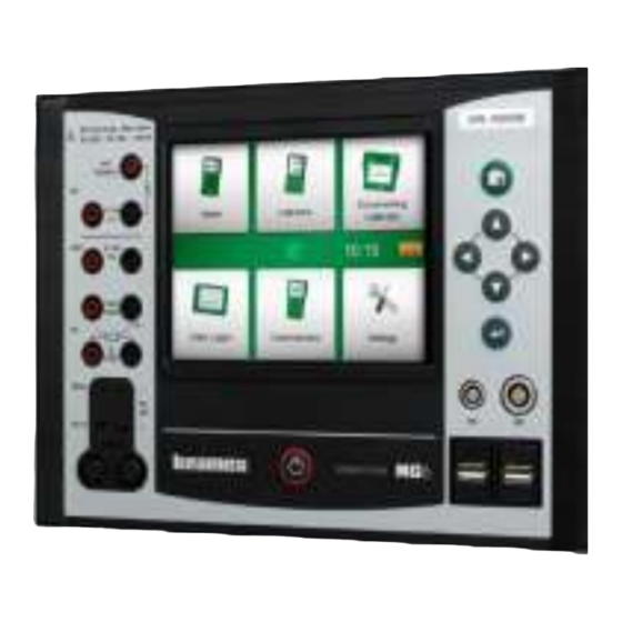
MC6 W TARTING ORKSTATION To start MC6 Workstation, switch the MCS200 Module Rack on and then press MC6 Workstation's Power button for a few seconds. The startup procedure ends in Home View (see picture on the right). From MC6 Workstation's Home View you may advance to any of the available main functions. -
Page 13: Firmware
About MC6 Workstation - Firmware IRMWARE You can interact with MC6 Workstation by tapping on available buttons/controls displayed on the touch screen. Optionally: use the hardware arrow keys to move between the available buttons/controls. The first time you push a hard- ware arrow key the Hardware Focus Indicator is displayed (a blue border Button without and with a Hardware Focus Indicator. - Page 14 MC6 Workstation, User Manual – Part 1, Introduction MC6 Workstation also has some "flat" buttons. They are used in, e.g lists. The color of the flat buttons may vary depending on the context. The following editable fields are available: ...
-
Page 15: Hardware
2. Thermocouple connector (TC2). For TC plugs with flat contacts. 3. RTD and Resistor connector (R1). An R2 connector is on the top of MC6 Workstation. More of R2 con- nector on page 9. 4. Voltage, Current and Frequency output (OUT). -
Page 16: Pressure Modules
The recommended pressure medium for pressure modules is clean air. Clean non-corrosive liquids may optionally be used in modules with a measuring range of 20 bar/300 psi or more. Avoid spilling liquid on MC6 Workstation when connecting/disconnecting pressure hoses to/from pressure modules. -
Page 17: Front Panel Connection Details
ACK OF ORKSTATION The rear end of MC6 Workstation (inside MCS200) includes the same connect- ors as in a portable MC6. There's also a Pressure Module connector for con- necting Pressure modules in MCS200. See picture below. USB Ports The need for USB connectors in MC6 Workstation may be more than is availa- ble in a portable MC6. -
Page 18: Memory
Available memory can be used for anything that requires it (e.g. instrument da- ta, calibration results etc.). ISPLAY MC6 Workstation has a backlit 640 × 480 pixel 5.7" TFT touch screen display. Warning! Use the touch screen with your fingers, gloves on or off. Optionally, use a stylus Using sharp tools such as a screwdriver on the touch meant for touch screen use. -
Page 19: Batteries
A picture of a battery (or a plug, when charging or running on AC power) is amount of power even when MCS200/MC6 Workstation is shown on many of MC6 Workstation's views. The "content" of the battery corre- switched off. Remember to check the capacity of the batteries sponds to the approximated charge level of MC6 Workstation's rechargeable from time to time when MC6 Workstation is not in use. -
Page 20: Pc Communication / Calibration Software
PC C OMMUNICATION ALIBRATION OFTWARE Beamex CMX Calibration Software supports MC6 Workstation from version V2, revision 2.8 and onwards and also in Beamex LOGiCAL, a cloud based tool for handling calibration results. USB C OMMUNICATION RIVER MC6 uses Windows' generic USB driver (WinUSB) provided by Microsoft. Sup- 7 …... -
Page 21: Options Software Options
Communicator, PROFIBUS PA Notes. Drivers for External Controllers (Pressure and Temperature) and The software options available in the MC6 at hand can be found in MC6's Settings main function. Select About option Special Temperature Sensors. and browse to page 3. -
Page 22: Hardware Modules/Options And Accessories
Pressure Hose Sets to be used together with internal and external Pressure Modules. ELATED RODUCTS There are an increasing number of devices that can be used together with MC6 Workstation. The following list includes devices that are already available (valid when this manual was printed): ... -
Page 23: Part 2, Active Terminals And Connections
Part 2 Things discussed in this part: A presentation of measurements MC6 Workstation is capable of performing. For all measurements, the ac- tive terminals together with useful additional infor- mation for that particular measurement are presented. Similarly, a presentation of generations and simula- tions MC6 Workstation is capable of performing. -
Page 24: General
For HART and Fieldbus instrument specifics, see Part 7, generations/simulations that MC6 Workstation is capable of performing. No Communicator. matter which of the available main functions you use in MC6 Workstation, the For information on External Devices (Pressure and Tempera- connections presented here apply. -
Page 25: Measurements Pressure Measurement
EASUREMENTS RESSURE EASUREMENT MC6 Workstation supports the use of both pressure modules in MCS200, if installed, and the use of supported external pressure modules, when they are connected to MC6 Workstation. Note that pressure measurement requires knowledge of pressure types (abso- lute pressure, gauge pressure and differential pressure). -
Page 26: Current Measurement
MC6 Workstation, User Manual – Part 2, Active Terminals and Connections URRENT EASUREMENT When measuring electric current, an important thing is selecting whether MC6 Workstation provides the 24 volt loop supply voltage or not. If not, an external device should provide the loop supply voltage. -
Page 27: Temperature Measurement (Thermocouple)
TC plugs. TC2 is for TC plugs with flat contacts. Check the Sensor Type. Your measurement results are unreliable unless you select the same sensor type as is connected to MC6 Workstation. Select also a suitable Reference Junction compensation method. Wrong settings yield use- less measurement results. -
Page 28: Resistance Measurement
MC6 Workstation, User Manual – Part 2, Active Terminals and Connections ESISTANCE EASUREMENT For R1 terminals: The two leftmost terminals are used in 2-wire systems. MC6 Workstation auto- matically checks the connection and displays the found wiring system (2-wire, 3-wire or 4-wire). For R2 terminal: Beamex offers, as an option, an adapter for the R2 terminal. -
Page 29: Pulse Counting
Trigger level. Select a level that suits your switch. See note to the right. Sound setting. Define whether MC6 Workstation emits a sound when the switch's state change and if yes, when it is emitted. See also: Pulse Counting on page 21 and Switch sensing terminals. -
Page 30: Using The Soft Numeric Keypad
This utility is useful when a generated/simulated value (or any numeric field in MC6 Workstation) is either empty (displaying dashes) or when a new and dif- ferent value is needed. The soft numeric keypad opens when you tap on the generated/simulated value (see picture to the right).Tap on numbers to enter a... -
Page 31: Generations/Simulations Changing The Generated/Simulated Value
Generations/Simulations - Changing the Generated/Simulated Value PINNING Spinning is a tool that is available in Calibrator and Documenting Calibrator. It is useful when making small changes to an existing numeric value, one digit at a time. Inactive spinner Non-empty numeric fields in Calibrator's generation/simulation windows have a button with both "Up"... -
Page 32: Current Generation (Source Or Sink)
Note. External Power Supply If the connected instrument utilizes digital communication and MC6 Workstation's 24 volt sup- ply voltage is in use, the following battery symbol is shown in the user interface of Document- Instrument ing Calibrator and Data Logger:... -
Page 33: Thermocouple Simulation
Thermocouple simulation terminals. Range depends on selected sensor type Warning! When using a thermocouple or an RTD sensor connected to MC6 Workstation to meas- Note. ure the external reference junction temperature: Keep in mind that there is no isolation Thermocouple measurements are error prone. There may be... -
Page 34: Resistance Simulation
Note. supported. With pulsed measurement current, set a wait time When simulating resistance or an RTD sensor, using R1 port, MC6 Workstation does not sup- of few milliseconds before the resistance is measured. port measuring the simulated signal using R2 port. -
Page 35: Pulse Generation
Generations/Simulations - Pulse Generation ULSE ENERATION Before generating pulses, the following settings should be checked: Frequency. To set the frequency, tap on the button with the "Hz" value. Amplitude. Defined from the button with the "V" value. Waveform and Duty Cycle. -
Page 36: Thermocouple Connections
Internal is the simplest. Use suitable thermocouple, extension or compensation of TC measurements. wires to connect to MC6 Workstation. MC6 Workstation takes care of the Ref- erence Junction compensation. The upper picture to the right presents the con- nection to TC1 terminals. You may optionally also use the TC2 terminals. -
Page 37: Part 3, Meter
Part 3 Things discussed in this part: Presenting the Meter and how to take it into use. ETER... -
Page 38: About Meter
MC6 Workstation. For calibration needs, use one the cali- bration related main functions available in MC6 Workstation. Start the Meter by tapping the Meter icon in MC6 Workstation's Home View (see adjacent picture). A window like the one on the lower right corner of this page opens. -
Page 39: Part 4, Calibrator
Part 4 Things discussed in this part: How to use the Calibrator Presenting the available additional Tools in Calibrator ALIBRATOR... -
Page 40: About Calibrator
Connections. Note. If you want to document your calibration results, use MC6 Workstation's optional Document- ing Calibrator feature or manually document the calibration data displayed in Calibrator. For information on External Devices (Pressure and Temperature Controllers) used together with Calibrator, see Part 9, Additional Information. -
Page 41: Tools
Tools - General OOLS ENERAL Calibrator window has Tools buttons in the lower left corner of each sub- window. See the picture to the right. The following list presents available tools. Certain tools are available for measurements only and others for genera- tions/simulations only. - Page 42 Tool is configured in. To stop, e.g. Damping, open the Damp- Ramp Available for generations/simulations: Opens a window ing configuration window and tap the "Stop" button. Then MC6 for defining a ramp function for the generated/simulated Workstation reverts to default damping settings.
-
Page 43: Part 5, Documenting Calibrator
Things discussed in this part: An introduction to calibration How to calibrate instruments using MC6 Workstation's Documenting Calibrator How to do a Group Calibration How to view calibration results How to read instrument data from devices... -
Page 44: General
MC6 Workstation, User Manual – Part 5, Documenting Calibrator ENERAL MC6 Workstation's Documenting Calibrator is an optional, more advanced tool than the "plain" Calibrator that is also available in MC6 Workstation. If your MC6 Workstation does not have this option installed, the Documenting Cali- brator icon is disabled. -
Page 45: Calibrating Instruments
Instruments are typically calibrated following the procedure shown in the adja- cent picture. In MC6 Workstation, you first select (or create) the instrument to be calibrated. Then perform the As Found calibration – as many repeats as is required - and decide whether or not adjustment is needed. -
Page 46: Instrument List
When you start the Documenting Calibrator, you arrive in Instrument List win- dow. See adjacent picture for an example of an Instrument List. MC6 Workstation allows you to hierarchically organize your instruments into a Plant Structure. The Instrument List window may contain both instruments (gray items) and Plant Structure Levels (yellow items). -
Page 47: Plant Structure Levels
Calibrating Instruments - Instrument List LANT TRUCTURE EVELS The name of the current Plant Structure Level is shown on the status bar. Tap on the bar to see the full Plant Structure path. Plant Structure Sub Levels have yellow background and the upper right corner is folded. The Level's name is displayed and on the lower right corner, the amount of further Sub Levels + the Current Plant Structure Level is called "Pulp". -
Page 48: Instrument Overview Window
MC6 Workstation, User Manual – Part 5, Documenting Calibrator NSTRUMENT VERVIEW INDOW When an instrument is selected, the Instrument Overview window opens and general data of the selected instrument is presented. See adjacent picture. With the help of the buttons on the right side of the window, you may ... - Page 49 When Automatic Acceptance is in use (checked), MC6 Workstation accepts calibration point automatically as follows: 1. MC6 Workstation uses the Max. Point Deviation value to see if the in- put signal is close enough to the next calibration point. 2. When close enough, MC6 Workstation checks the signal stability to de- cide whether the readings can be saved or not.
-
Page 50: Changing The Pressure Module During Calibration
MC6 Workstation, User Manual – Part 5, Documenting Calibrator When the calibration is completed, the first of Calibration Result window's pag- es open telling you whether the calibration Passed or Failed. Browse through the pages to get an overview of the calibration results. Note that the amount of pages shown depends on the setting found in the window's menu. -
Page 51: About Fieldbus And Hart Device Specifics
When adding a fieldbus instrument or a HART instrument's digital output to MC6 Workstation's database, select HART, FOUNDATION Fieldbus H1 or Profibus PA as the output quantity. See adjacent picture and note below. See also chapter Digital Communication and MC6 Workstation on page 48. Note. Documenting Calibrator's quantity selection window For HART instrument's analog output, select Current as the output quantity. -
Page 52: Group Calibration
MC6 Workstation, User Manual – Part 5, Documenting Calibrator ROUP ALIBRATION Note. MC6 Workstation's Group Calibration allows you to simultaneously calibrate Switches are not supported in group calibration. All other type several Instruments/Functions. This is practical, e.g. when calibrating Instru- of instruments/functions can be included in a group. -
Page 53: Editing A Group
Group Calibration - Calibrating a Group DITING A ROUP By default, the Instruments/Functions are calibrated in the order they were included in the group. However, the Instrument Overview window's menu includes a pos- sibility to sort the group according to your own needs. The same menu also in- cludes a possibility to cancel the Group or to remove the current Instru- ment/Function from the Group (in the Instrument menu option's sub-menu). -
Page 54: Group Settings
• A measurement loop, including a temperature transmitter, a local temperature indicator and a temperature indicator When the results of all Instruments/Functions are saved (or not), MC6 Work- in the control room. station returns to the Calibration window. Now you may do another calibration •... -
Page 55: Calibration Results Deleting Calibration Results
Calibration Results - Deleting Calibration Results ALIBRATION ESULTS Once an instrument has been calibrated, you may view saved calibration results as follows: When viewing the Instrument Overview Window, select the Calibra- tion Results button. The most recent saved calibration is presented. If you want to see older results, open the menu in Calibration Results window and select Results History. -
Page 56: Digital Communication And Mc6 Workstation
Part 7 of this manual. MC6 Workstation has pre-entered default mappings (which Digital Communica- tion Instrument field goes to which field in MC6 Workstation) but you may cus- tomize the mapping for each instrument model you use. ETTING AND... -
Page 57: Getting Default Mappings
In the adjacent picture you can see a sample of the mappings. The left side lists the fields in MC6 Workstation (target fields) and the Mapping Mode of the field (Generic in all cases of the sample picture). The right side lists the value and name of the field in the device. - Page 58 Defaults, only for Device Model Defaults. Notes. It is possible to map the same transmitter field into several MC6 Workstation fields. In the pic- ture on previous page, device's Tag is mapped both to Position ID and Device ID in MC6 Sample of default mappings for HART protocol.
-
Page 59: Part 6, Data Logger
Part 6 Things discussed in this part: An introduction Data Logger option and its capabili- ties. How to configure and start a Data Log. How to view, save and delete Data Log results. How to transfer Data Log results to a personal com- puter (PC). -
Page 60: General
MC6 Workstation, User Manual – Part 6, Data Logger ENERAL The Data Logger is an optional tool that allows you to collect data with MC6 Workstation. If the Data Logger option is purchased, the collected data may then be viewed, transferred to a personal computer (PC) and printed using a utility called Beamex MC6 Workstation Data Log Viewer. -
Page 61: Doing A Data Log Configuring
ONFIGURATIONS channel setup windows (when applicable). In addition to MC6 Workstation remembering the latest Data Log configurations, you may save useful configurations for future use. Saving and opening previ- ously saved configurations is available in the menu of Data Logger's main con-... -
Page 62: Starting The Data Log
MC6 Workstation, User Manual – Part 6, Data Logger TARTING THE Start the Data Log by tapping on the red "Record" button in the main configura- tion window's lower right corner. The button changes to a black "Stop" button allowing you to interrupt you Data Log, when necessary. -
Page 63: Viewing And Saving Or Deleting The Results
All pages include a possibility to either save or delete the Data Logging results. When saving, you have the possibility to give a descriptive name to the Data Logging results. MC6 Workstation automatically adds date and time to the Data Logging results. -
Page 64: Transferring Data Log Results To A Personal Computer
After the driver is installed, the software can be used for downloading the re- sults from MC6 Workstation and viewing the results. The data can be saved in viewer's native format (.LG6) or saved as CSV files. The latter format can easily be imported into spreadsheet software. -
Page 65: Part 7, Communicator
Part 7 Things discussed in this part: An introduction MC6 Workstation's Communicator and how it can be started. How to connect to an instrument capable of digital communication. Instructions on how to quickly select a varia- ble/parameter for use in Calibrator, Documenting Cal- ibrator or Data Logger. - Page 66 MC6 Workstation is shown. See lower picture to the right. Notes. Each communication protocol is a separate option in MC6 Workstation, so all protocols are not necessary enabled in your MC6 Workstation. This manual is not an introduction to HART and Fieldbus instruments. Get the know-how and terminology from books dedicated to HART and Fieldbus instruments and technology.
-
Page 67: General Warnings
In such a case, when returning an instrument with changed parameters to a live segment, Beamex cannot be held responsible for any damages caused by connecting MC6 Work- ensure that the parameters are also available in the control station to a live factory fieldbus segment. -
Page 68: Connections
Using an external power supply. Warning! When working in PROFIBUS PA: Do not connect two master devices (e.g. MC6 Work- station, a Field Communicator or a control system) at the same time to the same seg- ment! They clash and make the fieldbus segment unstable. Remove the instrument to be calibrated from the live segment for calibration. -
Page 69: Selecting The Instrument List Of Found Devices
A list of found devices. Note. If MC6 Workstation does not have the Device Description file for the selected instrument, a IMPORTANT! window opens informing you of the situation. Look for new Device Description files at When the calibrator is monitoring a fieldbus/HART seg- Beamex's web site: https://www.beamex.com. -
Page 70: About Instrument Parameters
ARAMETERS IN ENERAL This chapter briefly presents how Blocks, Records and Parameters of Digital Communication Instruments are viewed in MC6 Workstation and how you may browse through them. Elements seen while viewing/configuring an instrument: Blocks and Records have yellow background where the upper right cor- ner is folded. -
Page 71: Calibrating Or Data Logging Hart Instruments
Unfortunately the structure of data and naming conventions in HART instru- ments vary between different makes and models. Thus there is no single path from selecting the instrument in MC6 Workstation to locating the parameter. Refer to your instrument's manual to find the blocks where the parameters are located. -
Page 72: Editing Parameters
MC6 Workstation, User Manual – Part 7, Communicator DITING ARAMETERS With "editing parameters" we mean changing any editable parameter in the instrument's memory, e.g. selecting the type of process connection fitted to the instrument. Editing a Parameter is started by tapping on it. A window opens for editing the data. -
Page 73: Trimming A Fieldbus Instrument
About Instrument Parameters - Trimming a Fieldbus instrument RIMMING A IELDBUS INSTRUMENT Trimming a FOUNDATION Fieldbus or a Profibus PA instrument can be initi- ated from the Documenting Calibrator, provided the relevant communicator option is enabled and the instrument's Device Description contains information of parameters needed for trimming. -
Page 74: Trimming Ahart Instrument
Optionally, use one of the Copy buttons seen on the right side of the window to copy the reading available in the areas reserved for calibrator readings. To finalize the trim, continue as the trim method describes on MC6 Work- station's display. Notes. -
Page 75: Hart Device Description Specifics General
It presents the instrument's value parameters only in addition to basic Device Setup and Process Variable Settings. The default setting of Active Device Descriptions in MC6 may be defined in MC6 Workstation's Settings (see picture on the top right). Also: When con- necting to a HART device and selecting the supply, the tools button on the right HART in MC6 Workstation's Settings. -
Page 76: Basic View
Setup window (top right) and Process Variable Settings window (bottom right). Note. HART trimming is not supported when using MC6 Workstation's Basic View. Use another De- vice Description when trimming a HART instrument. Example of a Process Variable Settings Window. -
Page 77: Managing Smart Transmitter Configurations
MC6 Workstation (alternatively on a PC's hard disk) for easy configuration of the new transmitter replacing the broken one. Note. Please note that a saved configuration file cannot be written from MC6 Workstation back to a Configuration menu open. transmitter. -
Page 78: Viewing/Managing Configurations
MC6 W EAMEX ORKSTATION IELDBUS ONFIGURATION IEWER Beamex MC6 Fieldbus Configuration Viewer is a free tool for personal com- ® puters with Windows operating system. Download the Configuration Viewer software from Beamex's web site: https://www.beamex.com. Look for Down- load Center. - Page 79 Part 8 Things discussed in this part: How to configure MC6 Workstation to suit your own needs Briefly about re-calibrating/adjusting MC6 Workstation Optional security tool ETTINGS...
-
Page 80: Settings
MC6 Workstation, User Manual – Part 8, Settings ETTINGS This main function allows you to configure MC6 Workstation according to your own needs and also, recalibrate MC6 Workstation. The following set- tings/configurations are available: Language for selecting user interface language. -
Page 81: Optional Security Tool
PTIONAL ECURITY ENERAL Beamex CMX Calibration Software version 2, revision 2.11 and later include an optional tool called Mobile Security Plus. It is a tool that enforces security re- lated settings in mobile devices, including MC6 Workstation. For detailed infor- mation about Mobile Security Plus functionality, please see CMX User Guide. -
Page 82: Supervisor Window
MC6 Workstation, User Manual – Part 8, Settings UPERVISOR INDOW To access the Supervisor window, you need an admin PIN code. If the neces- sary option was purchased, the PIN code was shipped together with your cali- brator. For increased security, you should change the default admin PIN code to a personal one once you have entered the Supervisor window. - Page 83 Part 9 Things discussed in this part: How to create custom pressure units, PRT sensors and transfer functions. Basic Information on how to connect external devices like pressure controllers or temperature blocks to MC6 Workstation. DDITIONAL NFORMATION...
-
Page 84: Additional Information
MC6 Workstation, User Manual – Part 9, Additional Information DDITIONAL NFORMATION This section contains detailed information of some of MC6 Workstation's more extensive features. The ones presented here are: User Defined Pressure Units, on page 77, User Defined PRT / RTD Sensors, on page 78, ... -
Page 85: User Defined Pressure Units
Reference Unit and enter the Factor. The Factor is the rela- tionship between the Reference Unit and the custom pressure unit. The Refer- ence Unit may be any of the pre-entered pressure units available in MC6 Workstation. -
Page 86: User Defined Prt / Rtd Sensors
EFINED ENSORS ENERAL Just as pressure units, MC6 Workstation has a wealth of pre-entered standard Platinum Resistance Thermometer (PRT) type RTD sensors. They are available wherever you may select RTD Temperature as the Quantity. However, when using a PRT sensor as a reference sensor, the available standard sensors aren't necessary of use. -
Page 87: Callendar Van Dusen Formula For Prts
). Additionally, a constant, R , is needed to define the sensor. MC6 Workstation supports the use of the equation using coefficients A, B and C only. If your PRT's calibration certificate includes coefficients , and , use the following equations to convert them to A, B and C: ... - Page 88 Sensor Range entered in the 1 configuration page defines how many ad- ditional User Sensor pages is added to MC6 Workstation. If the range includes temperatures below zero, the total amount of configuration pages is four: 1. First page for general settings. See page 78.
-
Page 89: Factor
MC6 Workstation is the same as on the calibration certificate. If yes, the entered coefficients in MC6 Workstation are correct. If not, check the coeffi- cients you entered. -
Page 90: User Defined Transfer Functions
MC6 Workstation, User Manual – Part 9, Additional Information EFINED RANSFER UNCTIONS Transfer Functions are available in Calibrator's Scaling Tool and in instru- ment definitions found in Documenting Calibrator. When creating/selecting a user defined transfer function, tap on the Transfer Function button and browse to the User Transfer Function page. -
Page 91: User Defined Steps / Calibration Points
Additional Information - User Defined Steps / Calibration Points EFINED TEPS ALIBRATION OINTS These are available for instruments in Documenting Calibrator and also in Calibrator's Step tool. Use either Calibration Points or Step Definition button to modify its setting. In the opened window, browse to User Test Points page. The configuration consists of two (or more) pages as shown in the pictures to the right of this text. -
Page 92: Controller Communication
See lowermost picture to the right. In CMX, this corresponds to Input Method Controlled. Important! When connecting a Beamex FB or MB Temperature Dry Block to MC6 Workstation, en- sure that both devices are up and running before connecting a communication cable and invoking communication between them. -
Page 93: Configuring Controller Communication
Before utilizing External Controllers, both the communication cable / driver and the controller itself need to be configured in MC6 Workstation. We recommend this to be done using the Controller Preset window available in MC6 Work- station's main function Settings. MC6 Workstation supports up to four presets. - Page 94 MC6 Workstation, User Manual – Part 9, Additional Information...
-
Page 95: Appendix
Appendix Things discussed in this part: Safety Issues and Warnings Disposal of Waste Electrical and Electronic Equipment Servicing MC6 Workstation Statements and Warranty Index PPENDIX... -
Page 96: Safety
PPROVALS Safety Directive 2006/95/EC, EN 61010-1:2001 Directive 2004/108/EC, EN 61326-1:2006 YMBOLS The following symbols concerning electrical safety are used in MC6 Work- station. Alternating current, AC Direct current, DC Caution! See manual for further information... -
Page 97: Safety Precautions And Warnings
ENERAL ARNINGS Do not use MC6 Workstation in any other way than as described in this User Manual. If Do not tap the touch screen with sharp or hard objects or this equipment is used in a manner not specified by the manufacturer, the protection press hard on the display, especially with fingernails. -
Page 98: Warnings Concerning The Lithium Polymer Battery Pack
Removing/Replacing the MC6 Work- station's Battery Pack on page 98. To avoid short circuit- Always use battery pack delivered by Beamex. Use of battery packs not meant for MC6 ing the terminals, insulate them with adhesive tape. Final- Workstation is dangerous. - Page 99 If the battery pack starts to heat up or deform, stop charging process immediately and disconnect the charger. Place MC6 Workstation in a fire proof location and wait for ap- prox. 15 minutes. If no problems occur, try charging again, but be extra careful and oversee how the charging progresses.
-
Page 100: Warnings Concerning Electrical Measurement And Generation
Do not exceed 60 VDC / 30 VAC / 100 mA between any terminals. Maximum output voltage from MC6 Workstation's terminals is below 30 V. If you, how- ever, connect together voltages from the IN and OUT sections or if you connect external... -
Page 101: Warnings Concerning High Pressure
Safety - Safety Precautions and Warnings ARNINGS ONCERNING RESSURE High pressure is always dangerous. Only personnel with good experience and Check what the local regulations say about construction knowledge of high pressure liquid, air and nitrogen operations are allowed to work with and use of pressurized vessels. -
Page 102: Disposal Of Waste Electrical And Electronic Equipment
ATTERY MC6 Workstation contains a Lithium Polymer (LiPo) battery pack. Before dis- posing of MC6, discharge the battery pack, then remove it from MC6 (see chap- ter Removing Replacing the Batteries in Part 1, Introduction). Further infor- mation of the battery pack is in chapter Warnings Concerning the Lithium... -
Page 103: Service
ORKSTATION Note. If MC6 Workstation needs cleaning, use cloth soaked with a mild solution of tall To clean the display, use a microfiber cloth. If necessary, use a oil soap (pine soap). Wait a few minutes and then clean using a cloth moistened mild detergent and remove it thoroughly when ready. -
Page 104: Firmware Update
With one hand: Press and hold down the Left Arrow and Right Arrow keys in MC6 Workstation. With the other hand: Press and hold down the Home and Enter keys in MC6 Workstation. Hold the keys down until MC6 Workstation restarts. -
Page 105: Recalibrating Mc6 Workstation
MC6 Workstation's lifetime. During the calibration procedure, it is recommended to discon- MC6 Workstation is a high-accuracy calibrator and it should be recalibrated only nect the charger to avoid possible disturbances. Also: Ensure at laboratories being able to offer sufficient uncertainty. Please note that all cal- MC6 Workstation's batteries are fully charged. -
Page 106: Mc6 Workstation's Battery Pack And Charger
When the battery pack is full, only the plug symbol is shown. BOTH IN APPENDIX. If MC6 Workstation is shut off and MCS200 bench is still on, a battery symbol appears. After a while, an estimate of the remaining charge time appears below the battery symbol. -
Page 107: Statements Disclaimer
(including but not limited to damage for third par- ties and loss of use, loss of profit and loss of production) in relation with the use of this manual, even if Beamex has been advised of the possibility of such damages. -
Page 108: Intellectual Property Rights
RADEMARKS “Beamex”, “Beamex – World-Class Calibration Solu- The content of this manual is the property of Beamex Oy Ab and/or its subsidi- aries and affiliates (referred hereinafter as Beamex). This manual and its con- tions as well as the color combination of green and... -
Page 109: Index
Removing/Replacing ........98 Check Boxes ..........5 Transferring Results to a PC ...... 56 Storing ............91 Viewing Results .......... 55 Cleaning MC6 ......... 95 Buttons ............7 Date & Time Format ........ 72 Communication Settings ......72 Accept ............5 Date/Time Fields ........ - Page 110 MC6 User Manual – Appendix Approvals ............ 88 Charger ............95 Cleaning ............. 95 Editable Fields Hand Pumps ........... 14 Recalibrating ..........97 Date/Time ............. 6 Hardware Focus Indicator ......5 Resetting ............ 96 Numeric ............6 Hardware Options ........14 Safety............
- Page 111 Trimming a HART Instrument ....66 Quick Access Buttons ......34 Standby Mode ........... 4 Typographical conventions ......3 Starting a Data Log ......... 54 Starting MC6 Workstation ......4 Stepping ..........34 Ramping ..........34 User Defined ..........83...
- Page 112 MC6 User Manual – Appendix Unpacking ..........3 Updating MC6's Firmware ....... 96 User Defined Calibration Points ....83 User Defined Pressure Units ....77 User Defined PRT Sensors ..... 78 User Defined Steps ......... 83 User Defined Transfer Functions .... 82 Viewing Smart Transmitter Configurations .........
Need help?
Do you have a question about the MC6 and is the answer not in the manual?
Questions and answers