BEAMEX MC6 User Manual
Advanced field calibrator and communicator
Hide thumbs
Also See for MC6:
- Quick start manual ,
- User manual (112 pages) ,
- Quick reference manual (13 pages)
Table of Contents
Advertisement
Quick Links
U
M
SER
ANUAL FOR
B
MC6 A
®
EAMEX
Applies to firmware version 1.70
Dear user,
We have made every effort to ensure the accuracy of the contents of this man-
ual. Should any errors be detected, we would greatly appreciate to receive sug-
gestions to improve the quality of the contents of this manual.
For more detailed technical data about Beamex
tor and Communicator, please contact the manufacturer.
F
DVANCED
IELD
®
MC6 Advanced Field Calibra-
8860000 / MC6uEng / Version 1.7
C
ALIBRATOR AND
© Beamex 2012 - 2016
BEAMEX OY AB
Ristisuonraitti 10
FIN-68600 Pietarsaari
FINLAND
Tel
Fax
E-mail:
Internet:
C
OMMUNICATOR
+358 - 10 – 5505000
+358 - 10 – 5505404
sales@beamex.com
service@beamex.com
http://www.beamex.com
Advertisement
Table of Contents

Related Manuals for BEAMEX MC6


Summary of Contents for BEAMEX MC6
- Page 1 Should any errors be detected, we would greatly appreciate to receive sug- gestions to improve the quality of the contents of this manual. ® For more detailed technical data about Beamex MC6 Advanced Field Calibra- tor and Communicator, please contact the manufacturer.
-
Page 3: Table Of Contents
Spinning ................ 23 Connectors on Top of MC6 ..........8 Current Generation (Source or Sink) ........24 Connectors on the Right Side of MC6 ......8 Voltage Generation .............. 24 Internal Barometric Pressure Module ....... 9 Thermocouple Simulation ............ 25 Memory ................ - Page 4 Starting the Data Log ............56 Instrument Overview Window ..........41 Viewing and Saving or Deleting the Results ......57 Calibrating an Instrument Using MC6 ........41 Viewing Saved Data Log Results .......... 57 Changing the Pressure Module During Calibration ..43 Transferring Data Log Results to a Personal About Fieldbus and HART Device Specifics ....
- Page 5 Communication ............. 86 Tools in MC6 ................ 71 Configuring Controller Communication ......87 Saving Configurations ............ 71 Changing Controller During Calibration ......87 Viewing/Managing Configurations ........72 Beamex MC6 Fieldbus Configuration Viewer ......72 Uploading Configurations..........72 Linking Configurations to CMX........72...
- Page 6 Disposal of Waste Electrical and Electronic Equipment Beamex and WEEE ............. 96 Disposal of Battery Pack ..........96 Service Sending MC6 for Service ............. 97 Firmware Update..............97 Resetting MC6 ..............97 The Battery Charger ............. 98 Recalibrating MC6 ..............98 Cleaning MC6 ..............
- Page 7 Only the next page needs to be strictions; fill in the form when you feel like it (all items need not be answered). faxed to us. Then send it to Beamex using one of the possibilities listed to the right. Internet: http://www.beamex.com...
- Page 8 ____________________________________________ How helpful was the manual in using the product? (Tick a box in the percentage scale below) 10. Any ideas You want to propose to Beamex so that we can im- prove our products, operations and/or services. ____________________________________________ How well did the product suit your needs?
-
Page 9: Part 1, Introduction
Part 1 Things discussed in this part: About this manual Briefly about MC6's hardware and firmware Available software and hardware options NTRODUCTION... -
Page 10: General
HERE The header of each spread in MC6 User Manual informs you of where you are: Example of even page header: MC6 User Manual – Part 1, Introduction The even page shows the part you are in and the odd page shows the main topic you are currently viewing. -
Page 11: Typographical Conventions
NPACKING AND NSPECTION At the factory each new MC6 passes a careful inspection. It should be free of Standard accessories: scrapes and scratches and in proper operation order upon receipt. The receiver ... -
Page 12: About Mc6
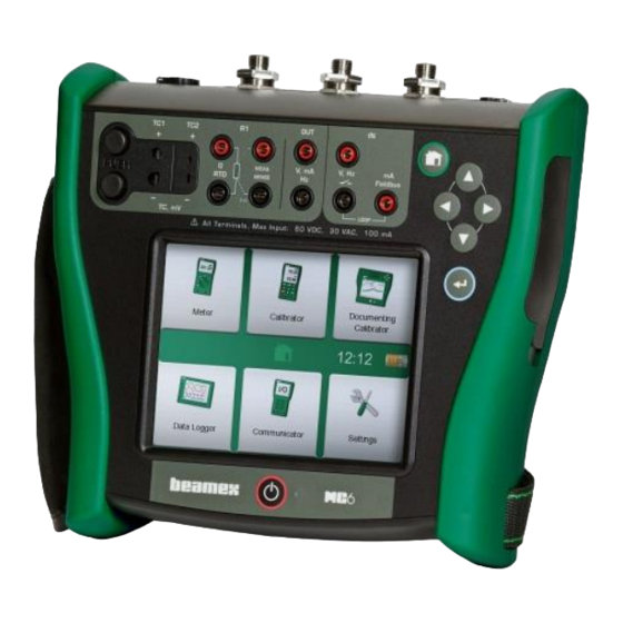
BOUT TARTING Start MC6 by pressing the Power button for a few seconds. The startup proce- dure ends in Home View (see picture on the right). From MC6's Home View you may advance to any of the available main functions. This manual contains detailed information of main functions as follows: Power button (left) and Home button (right). -
Page 13: Firmware
About MC6 - Firmware IRMWARE You can interact with MC6 by tapping on available buttons/controls displayed on the touch screen. Optionally: use the hardware arrow keys to move between the available buttons/controls. The first time you push a hardware arrow key the Hardware Focus Indicator is displayed (a blue border around the active but- Button without and with a Hardware Focus Indicator. - Page 14 MC6 User Manual – Part 1, Introduction MC6 also has some "flat" buttons. They are used in, e.g lists. The color of the flat buttons may vary depending on the context. The following editable fields are available: Text Fields, ...
-
Page 15: Hardware
For cables and standard TC plugs. 2. Thermocouple connector (TC2). For TC plugs with flat contacts. 3. RTD and Resistor connector (R1). An R2 connector is on the top of MC6. More of R2 connector on next page. 4. Voltage, Current and Frequency output (OUT). -
Page 16: Connectors On Top Of Mc6
OP OF Items from left to right: R2. A possibility to connect an external RTD sensor to MC6. See also Hardware Modules/Options and Accessories on page 14. P1 to P3. Internal Gauge Pressure Module connectors. These are op- tional. -
Page 17: Internal Barometric Pressure Module
Available memory can be used for anything that requires it (e.g. instrument da- ta, calibration results etc.). ISPLAY MC6 has a backlit 640 × 480 pixel 5.7" TFT touch screen display. Use the touch Warning! screen with your fingers, gloves on or off. Optionally, use a stylus meant for Using sharp tools such as a screwdriver on the touch touch screen use. -
Page 18: Batteries
TERY PACK AND CHARGING THE LITHIUM POLYMER BATTERY PACK, If MC6 is shut off and the charger is connected, a battery symbol appears. After BOTH IN APPENDIX. a while, an estimate of the remaining charge time appears below the battery... - Page 19 1. Important! Make sure charger is not connected to MC6. 2. Shut off MC6 and turn it upside down (the display facing the table top). Twist and remove the support. 3. Unscrew the four screws holding the battery compartment cover. See adjacent picture.
-
Page 20: Pc Communication / Calibration Software
A USB communication driver for communication between MC6 and a personal There are USB drivers for both 32 bit operating systems and computer (PC) is available in the CD-ROM shipped with MC6. If you do not for 64 bit operating systems. When installing the driver, the op-... -
Page 21: Options
Communicator, FOUNDATION Fieldbus Communicator, PROFIBUS PA Drivers for External Devices and Special Temperature Sensors. Requires that communicating hardware is installed into MC6. Please contact Beamex. When necessary, a connection cable is shipped when the software option is bought. -
Page 22: Hardware Modules/Options And Accessories
Spare Battery Pack. ELATED RODUCTS There are an increasing number of devices that can be used together with MC6. The following list includes devices that are already available (valid when this manual was printed): External Pressure Modules (EXT), Beamex Field Temperature Block (FB Series), ... -
Page 23: Part 2, Active Terminals And Connections
Part 2 Things discussed in this part: A presentation of measurements MC6 is capable of performing. For all measurements, the active termi- nals together with useful additional information for that particular measurement are presented. Similarly, a presentation of generations and simula- tions MC6 is capable of performing. -
Page 24: General
This section of MC6 User Manual presents all measurements and genera- For HART and Fieldbus instrument specifics, see Part 7, tions/simulations that MC6 is capable of performing. No matter which of the Communicator. available main functions you use in MC6, the connections presented here ap- For information on External Devices (Pressure and Tempera- ply. -
Page 25: Measurements Pressure Measurement
Measurements - Pressure Measurement EASUREMENTS RESSURE EASUREMENT MC6 supports the use of both internal pressure modules, if installed, and the use of supported external pressure modules, EXT, when they are connected to MC6. Note that pressure measurement requires knowledge of pressure types (abso- lute pressure, gauge pressure and differential pressure). -
Page 26: Current Measurement
Current measurement terminals. External supply. OLTAGE EASUREMENT MC6's voltage measurement terminals are listed below (top to bottom) as they are shown in the adjacent picture (left to right): TC1, measurement range: -1.01 to +1.01 VDC. TC2, measurement range: -1.01 to +1.01 VDC. -
Page 27: Temperature Measurement (Thermocouple)
TC2 is for TC plugs with flat contacts. Check the Sensor Type. Your measurement results are unreliable unless you select the same sensor type as is connected to MC6. Select also a suitable Reference Junction compensation method. Wrong settings yield useless measurement results. -
Page 28: Resistance Measurement
(2-wire, 3-wire or 4-wire). For R2 terminal: Beamex offers, as an option, an adapter for the R2 terminal. Please contact Beamex for details. R2 terminal always uses 4-wire measurement. Resistance measurement terminals. -
Page 29: Pulse Counting
Trigger level. Select a level that suits your switch. See note to the right. Sound setting. Define whether MC6 emits a sound when the switch's state change and if yes, when it is emitted. See also: Pulse Counting on page 21 and Switch sensing terminals. -
Page 30: Using The Soft Numeric Keypad
The entered value is taken into use when you close the window using the "Ac- cept" button. Note that MC6 may use the entered value as a source for the val- ue's resolution. Enter trailing zeros to ensure useful resolution. -
Page 31: Generations/Simulations Changing The Generated/Simulated Value
Generations/Simulations - Changing the Generated/Simulated Value PINNING Spinning is a tool that is available in Calibrator and Documenting Calibrator. It is useful when making small changes to an existing numeric value, one digit at a time. Inactive spinner Non-empty numeric fields in Calibrator's generation/simulation windows have a button with both "Up"... -
Page 32: Current Generation (Source Or Sink)
See also: Current Measurement on page 18. Range 0 … 55 mA Note. External If the connected instrument utilizes digital communication and MC6's 24 volt supply voltage is Power Supply in use, the following battery symbol is shown in the user interface of Documenting Calibrator Instrument... -
Page 33: Thermocouple Simulation
Thermocouple simulation terminals. Range depends on selected sensor type Warning! When using a thermocouple or an RTD sensor connected to MC6 to measure the exter- Note. nal reference junction temperature: Keep in mind that there is no isolation between the Thermocouple measurements are error prone. -
Page 34: Resistance Simulation
Notes. AC measurement current from the instrument under test is not When simulating resistance or an RTD sensor, using R1 port, MC6 does not support measur- supported. With pulsed measurement current, set a wait time ing the simulated signal using R2 port. -
Page 35: Pulse Generation
Generations/Simulations - Pulse Generation ULSE ENERATION Before generating pulses, the following settings should be checked: Frequency. To set the frequency, tap on the button with the "Hz" value. Amplitude. Defined from the button with the "V" value. Waveform and Duty Cycle. -
Page 36: Thermocouple Connections
Internal is the simplest. Use suitable thermocouple, extension or compensation treme conditions, wait up to 90 minutes. wires to connect to MC6. MC6 takes care of the Reference Junction compensa- tion. The upper picture to the right presents the connection to TC1 terminals. -
Page 37: Part 3, Meter
Part 3 Things discussed in this part: Presenting the Meter and how to take it into use. ETER... -
Page 38: About Meter
MC6. For calibration needs, use one the calibration related main functions available in MC6. Start the Meter by tapping the Meter icon in MC6's Home View (see adjacent picture). A window like the one on the lower right corner of this page opens. To measure a signal, do as follows: ... -
Page 39: Part 4, Calibrator
Part 4 Things discussed in this part: How to use the Calibrator Presenting the available additional Tools in Calibrator ALIBRATOR... -
Page 40: About Calibrator
One sub-window for the instrument's input and another for the instrument's output. Start the Calibrator by tapping on the Calibrator icon in MC6's Home View (see adjacent picture). A window like the one on the lower right corner of this page opens. -
Page 41: Tools
Tools - General OOLS ENERAL Calibrator window has Tools buttons in the lower left corner of each sub- window. See the picture to the right. The following list presents available tools. Certain tools are available for measurements only and others for genera- tions/simulations only. - Page 42 Tool is configured in. To stop, e.g. Damping, open the Damp- Ramp Available for generations/simulations: Opens a window ing configuration window and tap the "Stop" button. Then MC6 for defining a ramp function for the generated/simulated reverts to default damping settings.
-
Page 43: Part 5, Documenting Calibrator
Things discussed in this part: An introduction to calibration How to calibrate instruments using MC6's Documenting Calibrator How to do a Group Calibration How to view calibration results How to read instrument data from devices... -
Page 44: General
ENERAL MC6's Documenting Calibrator is an optional, more advanced tool than the "plain" Calibrator that is also available in MC6. If your MC6 does not have this option installed, the Documenting Calibrator icon is disabled. Documenting Calibrator saves instrument data and presents them in a list. -
Page 45: Calibrating Instruments
Instruments are typically calibrated following the procedure shown in the adja- cent picture. In MC6, you first select (or create) the instrument to be calibrated. Then perform the As Found calibration – as many repeats as is required - and decide whether or not adjustment is needed. -
Page 46: Instrument List
When you start the Documenting Calibrator, you arrive in Instrument List win- dow. See adjacent picture for an example of an Instrument List. MC6 allows you to hierarchically organize your instruments into a Plant Struc- ture. The Instrument List window may contain both instruments (gray items) and Plant Structure Levels (yellow items). -
Page 47: Instrument List Window Menu
Calibrating Instruments - Instrument List NSTRUMENT INDOW The Instrument List window's menu contains a lot of useful tools: Create New for creating a new Instrument etc. (See adjacent picture.) Sort for sorting the list contents alphabetically etc. Sorting icons shown in status bar (ascending / descending): Identification Due Date Creation... -
Page 48: Work Order View Mode
Instrument's general data and on a separate page among instrument data. All basic Note. data of Work Orders (Work Order Number and dates) are read only data in MC6. When Work Order View Mode is active, Plant Structure is not shown and instruments may not be copied or moved within the structure. -
Page 49: Instrument Overview Window
Calibrating Instruments - Instrument Overview Window NSTRUMENT VERVIEW INDOW When an instrument is selected, the Instrument Overview window opens and general data of the selected instrument is presented. See adjacent picture. With the help of the buttons on the right side of the window, you may ... - Page 50 When Automatic Acceptance is in use (checked), MC6 accepts calibration point automatically as follows: 1. MC6 uses the Max. Point Deviation value to see if the input signal is close enough to the next calibration point. 2. When close enough, MC6 checks the signal stability to decide whether the readings can be saved or not.
-
Page 51: Changing The Pressure Module During Calibration
Calibrating Instruments - Calibrating an Instrument Using MC6 When the calibration is completed, the first of Calibration Result window's pag- es open telling you whether the calibration Passed or Failed. Browse through the pages to get an overview of the calibration results. Note that the amount of pages shown depends on the setting found in the window's menu. -
Page 52: About Fieldbus And Hart Device Specifics
Adding fieldbus and HART Instrument to MC6's database When adding a fieldbus instrument or a HART instrument's digital output to MC6's database, select HART, FOUNDATION Fieldbus H1 or Profibus PA as the output quantity. See adjacent picture and note below. -
Page 53: Group Calibration
Group Calibration - Collecting Instruments/Functions for Group Calibration ROUP ALIBRATION Note. MC6's Group Calibration allows you to simultaneously calibrate several In- Switches are not supported in group calibration. All other type struments/Functions. This is practical, e.g. when calibrating Instruments/Func- of instruments/functions can be included in a group. -
Page 54: Editing A Group
MC6 User Manual – Part 5, Documenting Calibrator DITING A ROUP By default, the Instruments/Functions are calibrated in the order they were in- cluded in the group. However, the Instrument Overview window's menu in- cludes a possibility to sort the group according to your own needs. The same... -
Page 55: Group Settings
• A measurement loop, including a temperature transmitter, a local temperature indicator and a temperature indicator When the results of all Instruments/Functions are saved (or not), MC6 returns to in the control room. the Calibration window. Now you may do another calibration run or return to •... -
Page 56: Calibration Results
MC6 User Manual – Part 5, Documenting Calibrator ALIBRATION ESULTS Once an instrument has been calibrated, you may view saved calibration results as follows: When viewing the Instrument Overview Window, select the Calibra- tion Results button. The most recent saved calibration is presented. If you want to see older results, open the menu in Calibration Results window and select Results History. -
Page 57: Digital Communication And Mc6'S Instrument Data
More of Instrument's utilizing Digital Communication can be found in Part 7 of this manual. MC6 has pre-entered default mappings (which Digital Communication Instru- ment field goes to which field in MC6) but you may customize the mapping for each instrument model you use. ETTING AND... -
Page 58: Getting Default Mappings
In the adjacent picture you can see a sample of the mappings. The left side lists the fields in MC6 (target fields) and the Mapping Mode of the field (Generic in all cases of the sample picture). The right side lists the value and name of the field in the device. - Page 59 Defaults, only for Device Model Defaults. Notes. It is possible to map the same transmitter field into several MC6 fields. In the picture on previ- ous page, device's Tag is mapped both to Position ID and Device ID in MC6's instrument da- Sample of default mappings for HART protocol.
- Page 60 MC6 User Manual – Part 5, Documenting Calibrator...
-
Page 61: Part 6, Data Logger
Part 6 Things discussed in this part: An introduction Data Logger option and its capabili- ties. How to configure and start a Data Log. How to view, save and delete Data Log results. How to transfer Data Log results to a personal com- puter (PC). -
Page 62: General
MC6 User Manual – Part 6, Data Logger ENERAL The Data Logger is an optional tool that allows you to collect data with MC6. If the Data Logger option is purchased, the collected data may then be viewed, transferred to a personal computer (PC) and printed using a utility called Beamex MC6 Data Log Viewer. -
Page 63: Doing A Data Log
ONFIGURATIONS Note. For pressure measurements: In addition to MC6 remembering the latest Data Log configurations, you may The main configuration window's menu includes a possibility to save useful configurations for future use. Saving and opening previously saved zero gauge pressure modules. Zeroing is also possible in configurations is available in the menu of Data Logger's main configuration win- channel setup windows (when applicable). -
Page 64: Starting The Data Log
MC6 User Manual – Part 6, Data Logger TARTING THE Start the Data Log by tapping on the red "Record" button in the main configura- tion window's lower right corner. The button changes to a black "Stop" button allowing you to interrupt you Data Log, when necessary. -
Page 65: Viewing And Saving Or Deleting The Results
All pages include a possibility to either save or delete the Data Logging results. When saving, you have the possibility to give a descriptive name to the Data Logging results. MC6 automatically adds date and time to the Data Logging results. -
Page 66: Transferring Data Log Results To A Personal Computer
Beamex's web site http://www.beamex.com. Look for downloads section. Before you read data from MC6, you must connect MC6 to your PC using the USB cable provided. Then install the driver as presented in Part 1, Introduc- tion, chapter USB Communication Driver. -
Page 67: Part 7, Communicator
Part 7 Things discussed in this part: An introduction MC6's Communicator and how it can be started. How to connect to an instrument capable of digital communication. Instructions on how to quickly select a variable/pa- rameter for use in Calibrator, Documenting Calibrator or Data Logger. - Page 68 MC6 is shown. See lower picture to the right. Notes. Each communication protocol is a separate option in MC6, so all protocols are not necessary enabled in your MC6. This manual is not an introduction to HART and Fieldbus instruments. Get the know-how and terminology from books dedicated to HART and Fieldbus instruments and technology.
-
Page 69: General Warnings
In such a case, when returning an instrument with changed parameters to a live segment, ensure that the parameters Beamex cannot be held responsible for any damages caused by connecting MC6 to a live are also available in the control system's permanent data- factory fieldbus segment. -
Page 70: Connections
However, when using longer connecting cables there may be need for fieldbus terminators. Warning! When working in PROFIBUS PA: Do not connect two master devices (e.g. MC6, a Field Fieldbus/HART Communicator or a control system) at the same time to the same segment! They clash Instrument and make the fieldbus segment unstable. -
Page 71: Selecting The Instrument
Note. If MC6 does not have the Device Description file for the selected instrument, a window opens informing you of the situation. Look for new Device Description files at Beamex's web site: http://www.beamex.com. Install a downloaded Device Description file using the Device De- scription Installer software available, e.g. -
Page 72: About Instrument Parameters
ARAMETERS IN ENERAL This chapter briefly presents how Blocks, Records and Parameters of Digital Communication Instruments are viewed in MC6 and how you may browse through them. Elements seen while viewing/configuring an instrument: Blocks and Records have yellow background where the upper right corner is folded. -
Page 73: Calibrating Or Data Logging Hart Instruments
Thus there is no single path from selecting the instrument in MC6 to locating the parameter. Refer to your in- strument's manual to find the blocks where the parameters are located. Use the information presented on the previous page to browse the instrument data. -
Page 74: Editing Parameters
See also Warnings on page 61. Notes. This manual explains how the parameters are accessed using MC6. For detailed information of instrument data, refer to the manual of the instrument itself. Beamex cannot be held responsible for any damages caused... -
Page 75: Trimming A Fieldbus Instrument
About Instrument Parameters - Trimming a Fieldbus instrument RIMMING A IELDBUS INSTRUMENT Trimming a FOUNDATION Fieldbus or a Profibus PA instrument can be initi- ated from the Documenting Calibrator, provided the relevant communicator op- tion is enabled and the instrument's Device Description contains information of parameters needed for trimming. -
Page 76: Trimming Ahart Instrument
To finalize the trim, continue as the trim method describes on MC6's display. Notes. Just as in fieldbus instruments, the user interface and manuals of HART instruments are some- times using the misleading term "calibration"... -
Page 77: Hart Device Description Specifics
Device Setup and Process Variable Settings. The default setting of Active Device Descriptions in MC6 may be defined in MC6's Settings (see picture on the top right). Also: When connecting to a HART device and selecting the supply, the tools button on the right opens HART settings where HART in MC6's Settings. -
Page 78: Basic View
MC6 User Manual – Part 7, Communicator ASIC MC6's Basic View simplifies the use of HART instruments, since all that is seen are the instrument's value parameters in addition to basic Device Setup and Pro- cess Variable Settings. Select any value parameter you like for calibration, data logging etc. -
Page 79: Managing Smart Transmitter Configurations
MC6 (alternatively on a PC's hard disk) for easy configuration of the new transmitter replacing the broken one. Note. Please note that a saved configuration file cannot be written from MC6 back to a transmitter. Configuration menu open. -
Page 80: Viewing/Managing Configurations
Configuration options in protocol selection window. MC6 F EAMEX IELDBUS ONFIGURATION IEWER Beamex MC6 Fieldbus Configuration Viewer is a free tool for personal com- ® puters with Windows operating system. It is shipped on a DVD-ROM along with other MC6 tools. PLOADING... - Page 81 Part 8 Things discussed in this part: How to configure MC6 to suit your own needs Briefly about re-calibrating/adjusting MC6 ETTINGS...
-
Page 82: Settings
MC6 User Manual – Part 8, Settings ETTINGS This main function allows you to configure MC6 according to your own needs and also, recalibrate MC6. The following settings/configurations are available: Language for selecting user interface language. About. Information about installed modules, firmware options etc. -
Page 83: Security Plus
To access the Supervisor window, you need an admin PIN code. If the neces- sary option was purchased, the PIN code was shipped together with MC6. If needed, you can change the admin PIN code once you have entered Supervi- sor window. -
Page 84: Security Plus In Documenting Calibrator
MC6 User Manual – Part 8, Settings ECURITY LUS IN OCUMENTING ALIBRATOR The following Documenting Calibrator functionalities are either restricted with an admin PIN code or blocked, depending on the setting in Supervisor Window: Skipping or undoing a calibration point, ... - Page 85 Part 9 Things discussed in this part: How to create custom pressure units, PRT sensors and transfer functions. Basic Information on how to connect external devices like pressure controllers or temperature blocks to MC6. DDITIONAL NFORMATION...
-
Page 86: Additional Information
MC6 User Manual – Part 9, Additional Information DDITIONAL NFORMATION This section contains detailed information of some of MC6's more extensive features. The ones presented here are: User Defined Pressure Units, on page 79, User Defined PRT / RTD Sensors, on page 80, ... -
Page 87: User Defined Pressure Units
RESSURE NITS Wherever in MC6, when you use pressure as the Quantity, you may choose a pressure unit from a wealth of already available pressure units, divided into several pages. User defined pressure units may be added to the subsequent page(s). -
Page 88: User Defined Prt / Rtd Sensors
EFINED ENSORS ENERAL Just as pressure units, MC6 has a wealth of pre-entered standard Platinum Resistance Temperature (PRT) type RTD sensors. They are available wherever you may select RTD Temperature as the Quantity. However, when using a PRT sensor as a reference sensor, the available standard sensors aren't nec- essary of use. -
Page 89: Callendar Van Dusen Formula For Prts
). Additionally, a constant, R , is needed to define the sensor. MC6 supports the use of the equation using coefficients A, B and C only. If your PRT's calibration certificate includes coefficients , and , use the following equations to convert them to A, B and C: ... - Page 90 Sensor Range entered in the 1 configuration page defines how many ad- ditional User Sensor pages is added to MC6. If the range includes tempera- tures below zero, the total amount of configuration pages is four: 1. First page for general settings. See page 80.
-
Page 91: Factor
MC6 is the same as on the calibration certificate. If yes, the entered coefficients in MC6 are correct. If not, check the coefficients you entered. -
Page 92: User Defined Transfer Functions
MC6 User Manual – Part 9, Additional Information EFINED RANSFER UNCTIONS Transfer Functions are available in Calibrator's Scaling Tool and in instru- ment definitions found in Documenting Calibrator. When creating/selecting a user defined transfer function, tap on the Transfer Function button and browse to the User Transfer Function page. -
Page 93: User Defined Steps / Calibration Points
Additional Information - User Defined Steps / Calibration Points EFINED TEPS ALIBRATION OINTS These are available for instruments in Documenting Calibrator and also in Calibrator's Step tool. Use either Calibration Points or Step Definition button to modify its setting. In the opened window, browse to User Test Points page. The configuration consists of two (or more) pages as shown in the pictures to the right of this text. -
Page 94: Controller Communication
ONTROLLER OMMUNICATION MC6's communication with External Controllers (Pressure and Temperature) connected to the USB-A ports is optional. Check what options your MC6 has from the Settings window. Tap on the About button and browse to page with Installed Options information. -
Page 95: Configuring Controller Communication
MC6. We recommend this to be done using the Controller Preset window available in MC6's main function Settings. MC6 supports up to four presets. Each of the presets create a pair of a Connection Interface (communication cable / driver) and a Controller Type. - Page 96 MC6 User Manual – Part 9, Additional Information...
- Page 97 Appendix Things discussed in this part: Safety Issues and Warnings Disposal of Waste Electrical and Electronic Equipment Servicing MC6 Statements and Warranty Index PPENDIX...
-
Page 98: Safety
MC6 User Manual – Appendix AFETY MC6 has an IP65 water/dust proof case. The materials of MC6's case withstand normal industrial conditions. MC6 endures shocks with the help of the built in impact protectors. Internal pressure modules with a measuring range of 6 bar (90 psi) or less are overpressure protected. -
Page 99: Safety Precautions And Warnings
ENERAL ARNINGS Do not use MC6 in any other way than as described in this User Manual. If this equip- Do not tap the touch screen with sharp or hard objects or ment is used in a manner not specified by the manufacturer, the protection provided by press hard on the display, especially with fingernails. -
Page 100: Warnings Concerning The Lithium Polymer Battery Pack
Removing Replacing the Batteries in Part 1, Introduc- tion. To avoid short circuiting the terminals, insulate them Always use battery pack delivered by Beamex. Use of battery packs not meant for MC6 with adhesive tape. Finally, place battery pack in a fire is dangerous. - Page 101 If the battery pack starts to heat up or deform, stop charging process immediately and disconnect the charger. Place MC6 in a fire proof location and wait for approx. 15 minutes. If no problems occur, try charging again, but be extra careful and oversee how the charging progresses.
-
Page 102: Warnings Concerning Electrical Measurement And Generation
EASUREMENT AND ENERATION MC6's OUT section terminals are protected against over voltage and over current as far Although there is a galvanic isolation between MC6's IN as it has been possible without affecting the accuracy. Do not however connect signals and OUT sections, it is for functional purposes only. -
Page 103: Warnings Concerning High Pressure
Safety - Safety Precautions and Warnings ARNINGS ONCERNING RESSURE High pressure is always dangerous. Only personnel with good experience and Check what the local regulations say about construction knowledge of high pressure liquid, air and nitrogen operations are allowed to work with and use of pressurized vessels. -
Page 104: Disposal Of Waste Electrical And Electronic Equipment
ISPOSAL OF ATTERY MC6 contains a Lithium Polymer (LiPo) battery pack. Before disposing of MC6, discharge the battery pack, then remove it from MC6 (see chapter Removing Replacing the Batteries in Part 1, Introduction). Further information of the battery pack is in chapter Warnings Concerning the Lithium Polymer Bat- tery Pack on page 92. -
Page 105: Service
Transfer the update software to a USB Stick (USB Flash Memory). Make sure Updating MC6 firmware do not erase any user entered data MC6 is powered off. Connect the USB stick to one of MC6's USB-A ports. (instruments, calibration results, data logs etc.). -
Page 106: The Battery Charger
LEANING Note. If MC6 needs cleaning, use cloth soaked with a mild solution of tall oil soap To clean the display, use a microfiber cloth. If necessary, use a (pine soap). Wait a few minutes and then clean using a cloth moistened with mild detergent and remove it thoroughly when ready. -
Page 107: Statements
(including but not limited to damage for third par- ties and loss of use, loss of profit and loss of production) in relation with the use of this manual, even if Beamex has been advised of the possibility of such damages. -
Page 108: Intellectual Property Rights
RADEMARKS “Beamex”, “Beamex – World-Class Calibration Solu- The content of this manual is the property of Beamex Oy Ab and/or its subsidi- aries and affiliates (referred hereinafter as Beamex). This manual and its con- tions as well as the color combination of green and... -
Page 109: Index
Charging the Battery Pack ....... 93 Spare ............14 Check Boxes ..........5 Storing ............93 Buttons ............7 Cleaning MC6 ......... 98 Accept ............5 Communication Settings ......74 Damping ..........34 Check Boxes ..........5 Communicator ......... 60 Data Logger .......... - Page 110 MC6 User Manual – Appendix Date/Time Fields ........6 Disclaimer ..........99 Generation (see also Simulation) Display ............9 Changing the generated value ....22 Disposing MC6 ........96 Language ..........74 Current ............24 Documenting Calibrator ......36 Leak Test ..........33 Frequency ..........
- Page 111 Menu Button ..........5 Factor customization ........83 Scaling ............ 33 Meter ............30 ISO 90 ............81 Servicing MC6 ......... 97 Testing Custom Sensors......83 Settings ........... 74 User Defined ..........80 Simulation (see also Generation) Pulse Counting ........21 Changing the simulated value ....
- Page 112 MC6 User Manual – Appendix User Defined PRT Sensors ..... 80 User Defined Steps ......... 85 Temperature Blocks ........ 14 User Defined Transfer Functions .... 84 Temperature Controllers ......86 Configuring ..........87 Temperature Measurement ..... 19 Testing Leakage/Stability ......33 Viewing Smart Transmitter Text Fields ..........
Need help?
Do you have a question about the MC6 and is the answer not in the manual?
Questions and answers