Table of Contents
Advertisement
Request for the Customers
Read and understand this operating manual before using the detector.
Use the detector in accordance with the operating manual.
Regardless of warranty period, we shall not make any compensation for accidents and
damage caused by using this product.
The compensation shall be made only under the warranty policy of products or parts
replacement.
Because this is a safety unit, a regular maintenance for every six months and daily
maintenance must be performed.
If any abnormality is found in the gas monitor, notify it to RIKEN KEIKI immediately.
(Visit our Web site to find your nearest RIKEN KEIKI office.)
Smart transmitter/
Gas Detector Head
SD-1
Operating Manual
(PT2-160)
PT2E-1601
Advertisement
Table of Contents

Related Manuals for Riken Keiki SD-1


Summary of Contents for Riken Keiki SD-1
- Page 1 Because this is a safety unit, a regular maintenance for every six months and daily maintenance must be performed. If any abnormality is found in the gas monitor, notify it to RIKEN KEIKI immediately. (Visit our Web site to find your nearest RIKEN KEIKI office.)
- Page 2 Operating Precautions This detector is a gas detector that detects combustible gases in the air and triggers a gas alarm. The gas detector is a safety unit, not an analyzer or densitometer which performs quantitative/qualitative analysis/measurement for gases. Please fully understand the following points before using it, so that it can be used properly. This detector may be interfered by gases and vapors other than the gas to be detected.
-
Page 3: Table Of Contents
Operating Precautions <Contents> Outline of the Product ..................... 2 1-1. Preface ........................... 2 1-2. Purpose of use ....................... 2 1-3. Definition of DANGER, WARNING, CAUTION, and NOTE ..........2 Important Notices on Safety .................... 3 2-1. Danger cases ......................... 3 2-2. -
Page 4: Outline Of The Product
Outline of the Product 1-1. Preface Thank you for choosing our smart transmitter/gas detector head SD-1. Please check that the model number of the product you purchased is included in the specifications on this manual. This manual explains how to use the detector and its specifications. It contains information required for using the detector properly. -
Page 5: Important Notices On Safety
Do not open the lid when applying current. Do not attempt to repair the detector. For the lid, use hexagon socket head bolts specified by RIKEN KEIKI. Do not apply a strong force or shock to the window plate. The explosion-proof performances may be deteriorated due to damages. -
Page 6: Warning Cases
2 Important Notices on Safety 2-2. Warning cases 2-2. Warning cases WARNING Power supply Before turning on the detector, always check that the voltage is properly applied. Do not use an unstable power supply because it may cause malfunctions. Need of grounding circuit Do not cut the grounding circuit or disconnect the wire from the grounding terminal. -
Page 7: Precautions
2 Important Notices on Safety 2-3. Precautions 2-3. Precautions CAUTION Do not use a transceiver near the detector. Radio wave from a transceiver near the detector or its cables may disturb commands. If a transceiver is used, it must be used in a place where it disturbs nothing. To restart the detector, wait for five seconds or more before doing it. -
Page 8: Safety Information
Necessary information for explosion proof construction of Model SD-1. About Model SD-1 The Model SD-1 is a fixed mount, continuous-monitoring detector head and provides a 4-20mA signal which indicates the target gas reading for use by a gas monitoring controller, recording device, or programmable controller. -
Page 9: Product Components
3 Product Components 3-1. Gas detector and standard accessories Product Components 3-1. Gas detector and standard accessories <Main Unit> (including a cable gland) <Standard Accessories> Operating manual Dedicated handling lever (used for the wiring) Dedicated control key CAUTION Use the supplied dedicated control key to operate the detector. -
Page 10: Names And Functions For Each Part
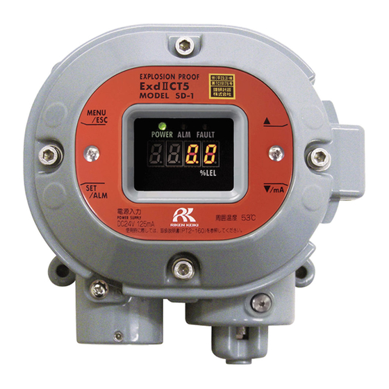
3 Product Components 3-2. Names and functions for each part 3-2. Names and functions for each part (6) Alarm lamp (7) Fault lamp (5) Power lamp (1) MENU/ESC key (3) key (8) Concentration value display (4) key (2) SET key Used to enter the maintenance mode. -
Page 11: Block Diagram
3 Product Components 3-3. Block diagram 3-3. Block diagram <Electric Diagram> Power supply part POWER INPUT (24 VDC) Display (POWER) (ALARM) (FAULT) Seven-segment LED Controller Alarm contact controller (four-digit) (CPU) Gas alarm contact (ALARM) Contact activation Magnetic operation part • De-energized (MENU/ESC) (▲) (▼) (SET) (De-energized at a normal environment) -
Page 12: How To Use
4 How to Use 4-1. Before using the detector How to Use 4-1. Before using the detector Not only the first-time users but also the users who have already used the product must follow the operating precautions. Ignoring the precautions may damage the detector, resulting in inaccurate gas detection. 4-2. -
Page 13: Precautions For System Designing
4 How to Use 4-3. Precautions for system designing Do not install the detector in a place where maintenance of the detector cannot be performed or where handling the detector involves dangers. Regular maintenance of the detector must be performed. Do not install the detector in a place where the machinery must be stopped when maintenance is performed in its inside, where parts of the machinery must be removed to perform maintenance, or where the detector cannot be removed because tubes or racks prevent access to it. - Page 14 4 How to Use 4-3. Precautions for system designing Proper use of alarm contact The alarm contact of the detector is used to transmit signals to activate an external buzzer, an alarm lamp or a rotating lamp. Do not use the detector for controlling purpose (e.g., controlling the shutdown valve.) The specifications for the alarm contact of the detector are based on the resistant load conditions.
-
Page 15: How To Install
4 How to Use 4-4. How to install 4-4. How to install <Installation Dimensions and Maintenance Space> Attach the detector on the wall and others using four M5 screws. CAUTION Do not install the detector in a place where maintenance of the detector cannot be performed or where handling the detector involves dangers. -
Page 16: How To Wire
4 How to Use 4-5. How to wire 4-5. How to wire CAUTION Be careful not to damage the internal electronic circuit when wiring. In addition, be careful not to apply stresses on the detector when (overweight) cables are installed. ... - Page 17 4 How to Use 4-5. How to wire <Figure of Terminal Plate> 24 VDC - (Common) 4 - 20 Sig+ Contact Contact Grounding terminal <Specifications of Terminal Plate> Specifications of terminal plate Rated voltage: 250 VAC Rated current: 12 A However, it depends on cables to be used.
- Page 18 4 How to Use 4-5. How to wire CAUTION The specified bare wire length must be observed when the wire insulation is peeled off. Improper clamping of the wire due to a shorter bare wire length may cause defective electrification or heating.
- Page 19 4 How to Use 4-5. How to wire <Attaching External Cable> CAUTION Tighten a cable gland with a tool until a clearance between the cable gland and a main unit case is below 1.5 mm. If it is difficult to tighten the cable gland, grease its screw part and then tighten it with the tool. - 17 -...
- Page 20 For the grounding wire, use cable lugs to safely connect it to a grounding terminal without looseness or twist. <Wiring Example> Connecting to the indicator SD-1 1 2 3 4 5 RM-593, etc. +24 V Connecting to the upper unit (DCS, PLC)
-
Page 21: How To Operate
5 How to Operate 5-1. Preparation for start-up How to Operate 5-1. Preparation for start-up Before supplying power, read and understand the following precautions. Ignoring these precautions may cause an electric shock or damage the detector. Connect the detector to a grounding circuit. ... -
Page 22: How To Start The Detector
5 How to Operate 5-3. How to start the detector WARNING When the detector enters other mode from the detection mode while an alarm is activated, the alarm is reset. 5-3. How to start the detector Before supplying power (24 VDC) to the detector, check that the detector is installed properly. ... -
Page 23: Modes
5 How to Operate 5-4. Modes 5-4. Modes Details on each mode are provided as follows. CAUTION Do not change the settings if not necessary. Changing the settings without understanding the specifications may cause malfunctions. Mode Item LED display Details Detection Normal state... -
Page 24: User Mode
5 How to Operate 5-5. User mode 5-5. User mode WARNING After the adjustment is completed, never fail to press MENU/ESC key to return to the detection mode. (If the detector remains in the user mode, it automatically returns to the detection mode in ten hours.) Show Various Settings - 22 -... - Page 25 5 How to Operate 5-5. User mode <Zero Adjustment "1-1"> This is used to perform the zero adjustment. NOTE If the zero calibration failed since the zero point was significantly fluctuated from around zero, it returns to 1-1 after FAIL rather than PASS is displayed. In this case, the zero adjustment has not been completed. - 23 -...
-
Page 26: How To Exit
5 How to Operate 5-6. How to exit <Setting Display "1-2"> Display various setting values. Press SET key. AL.: The contact is activated due to the gas alarm. FAU.: The contact is activated due to the fault alarm. A.orF.: The contact is activated due to the gas alarm or the fault alarm. -
Page 27: Operations And Functions
6 Operations and Functions 6-1. Gas alarm activation Operations and Functions 6-1. Gas alarm activation Gas alarm: Activated when the concentration of detected gas reaches or exceeds the alarm setpoint value. <<Auto-Reset>> NOTE The alarm setpoint is factory-set. Although the alarm delay time (standard: 2 seconds) works in the detector to prevent a false activation, it can be cancelled if not needed. -
Page 28: Fault Alarm Activation
6 Operations and Functions 6-2. Fault alarm activation <Response to Gas Alarm> A gas concentration value exceeds the alarm setpoint When a gas alarm is triggered, take actions in accordance with your management rules of gas alarm. Normally, take the following actions. ... -
Page 29: External Output Operation
6 Operations and Functions 6-3. External output operation 6-3. External output operation Signal Transmission System Electric current transmission (non-isolated) 4 – 20 mA Transmission Path CVVS Transmission Distance CVVS 1.25 sq: Maximum 1 km Connection Load Resistance Below 300 Ω Detection Mode (No Alarm) 4 - 20 mA (concentration output) Detection Mode (Gas Alarm) -
Page 30: Other Functions
6 Operations and Functions 6-4. Other functions 6-4. Other functions <Suppression Function> The sensors used with the detector are influenced by environmental changes (temperature, humidity, and other characteristics) or interference gases (interference characteristics) in no small measure, which affects the reading. Therefore, the reading might be fluctuated around zero even in a normal environment. This function obscures influences by environmental changes and interference gases around zero that have no meaning for your management rules of gas alarm. -
Page 31: Maintenance
7 Maintenance 7-1. Maintenance intervals and items Maintenance This is an important instrument for the purpose of safety. To maintain the performance of the detector and improve the reliability of safety, perform a regular maintenance. 7-1. Maintenance intervals and items ... - Page 32 7 Maintenance 7-1. Maintenance intervals and items Main Services Power Supply Checks the power supply voltage. Check Verifies that the power lamp lights up. (Verifies that relevant points can be identified on the system.) (When a UPS (uninterruptible power system) is used, checks the operation with the UPS (uninterruptible power system).) Concentration Verifies that the concentration display value is zero (or 20.9 vol% on the oxygen deficiency...
-
Page 33: Regular Maintenance Mode
7 Maintenance 7-2. Regular maintenance mode 7-2. Regular maintenance mode WARNING After the adjustment is completed, never fail to press MENU/ESC key to return to the detection mode. (If the detector remains in the maintenance mode, it automatically returns to the detection mode in ten hours.) Mode Item... - Page 34 7 Maintenance 7-2. Regular maintenance mode User Mode In "1-3.", press SET key. Then press SET key again for three seconds. Regular Maintenance Mode 2-0. Test Mode Test Mode Perform various tests. => P33 2-1. Zero Adjustment Zero Adjustment Perform the zero =>...
- Page 35 7 Maintenance 7-2. Regular maintenance mode <Alarm Test Mode "2-0"> Press SET key. Gas Test 2-0.0 Gas Test => P34 Alarm Test 2-0.1 Alarm Test => P34 Fault Test 2-0.2 Fault Test => P35 LED Test 2-0.3 LED Test => P35 Memory Test 2-0.4 Memory Test =>...
- Page 36 7 Maintenance 7-2. Regular maintenance mode <Gas Test "2-0.0"> 2-0.0 Press SET key. Introduce the test gas and perform the gas test. Stop introducing the test gas. When the reading drops, press MENU/ESC key to cancel the test and to go back to the original state.
- Page 37 7 Maintenance 7-2. Regular maintenance mode <Fault Alarm Test "2-0.2"> 2-0.2 Press SET key. Fault Test ON/OFF Select either ON/OFF. Switch ON and press SET key to activate the fault alarm. Return to OFF and press SET key to deactivate the fault alarm. (Pressing MENU/ESC key also enables to cancel this menu and to go back to the original state.)
- Page 38 7 Maintenance 7-2. Regular maintenance mode <Memory Test "2-0.4"> 2-0.4 Press SET key. When StA. is displayed, press SET key again. When CAL. is displayed, the memory diagnosis is performed. When memory is correct as a result of the diagnosis, PASS is displayed. Press SET key to go back to the original state.
- Page 39 7 Maintenance 7-2. Regular maintenance mode <Environmental Setting "2-4"> Set various operations and functions in the environmental setting. <<Environmental Setting 1>> 2-4. Environmental Setting Press SET key. 2-4.0 This is factory-set and not typically used by the user. 2-4.1 INHIBIT Setting Set INHIBIT.
-
Page 40: Gas Calibration Method
7-3. Gas calibration method 7-3. Gas calibration method Perform a gas calibration in each mode (zero adjustment <<SD-1>> mode and span adjustment mode) using the calibration gas. Zero adjustment gas Span adjustment gas (collected in a gas sampling bag) ... - Page 41 7 Maintenance 7-3. Gas calibration method Press SET key. Current Concentration Value Display Press SET key to perform the zero adjustment. Under Zero Adjustment (CAL. is displayed) Wait for a while until the adjustment is completed. Zero Adjustment Completed It automatically returns to 2-1 after PASS is displayed.
- Page 42 7 Maintenance 7-3. Gas calibration method <Span Adjustment "2-2"> This is used to perform the span adjustment. CAUTION Before starting the span adjustment, provide the detector with the span adjustment gas and wait until the indicator is stabilized. NOTE Japan Gas Appliances Inspection Association certification products ask you for spans adjustment so that you may use our maintenance services.
-
Page 43: Parts Replacement
7 Maintenance 7-4. Parts replacement 7-4. Parts replacement <Sensor Replacement> Our service engineers need to replace the sensor and perform the gas calibration. Please contact our overseas sales department or local representatives. NOTE The gas calibration using the standard gas is required after the sensor is replaced. Please request it to our overseas sales department or local representatives. -
Page 44: Storage, Relocation And Disposal
8 Storage, Relocation and Disposal 8-1. Procedures to store the detector or leave it for a long time Storage, Relocation and Disposal 8-1. Procedures to store the detector or leave it for a long time The detector must be stored under the following environmental conditions. ... -
Page 45: Troubleshooting
9 Troubleshooting 9 Troubleshooting Troubleshooting The troubleshooting does not explain the causes of all the malfunctions which occur on the detector. This simply helps to find the causes of malfunctions which frequently occur. If the detector shows a symptom which is not explained in this manual, or still has malfunctions even though remedial actions are taken, please contact our overseas sales department or local representatives. - Page 46 9 Troubleshooting 9 Troubleshooting <Abnormalities of Readings> Symptoms Causes Actions Drifting of sensor Perform the zero adjustment. output Disturbances by interference gases, such as solvents, cannot be eliminated completely. Presence of For information on actions, such as removal filter, please interference gas contact our overseas sales department or local The reading rises...
-
Page 47: Product Specifications
10 Product Specifications 10-1. List of specifications Product Specifications 10-1. List of specifications [SD-1 (TypeGP)] <Japanese Specifications> Detection principle Catalytic combustion type Gas to be detected Combustible gas Concentration display Seven-segment LED (four-digit) Detection range 0 - 100% LEL Display resolution 0.5% LEL... - Page 48 10 Product Specifications 10-1. List of specifications [SD-1 (TypeNC)] <Japanese Specifications> Detection principle New ceramic type Gas to be detected Combustible gas Concentration display Seven-segment LED (four-digit) Detection range Depending on the gas to be detected Detection method Diffusion type...
- Page 49 10 Product Specifications 10-1. List of specifications [SD-1 (TypeGP)] <Overseas Specifications> Detection principle Catalytic combustion type Gas to be detected Combustible gas Concentration display Seven-segment LED (four-digit) Detection range 0 - 100% LEL Display resolution 0.5% LEL Detection method Diffusion type...
-
Page 50: List Of Accessories
10 Product Specifications 10-2. List of accessories [SD-1 (TypeNC)] <Overseas Specifications> Detection principle New ceramic type Gas to be detected Combustible gas Concentration display Seven-segment LED (four-digit) Detection range Depending on the gas to be detected Detection method Diffusion type... -
Page 51: Detection Principle
10 Product Specifications 10-3. Detection principle 10-3. Detection principle [Catalytic Combustion Type] When a combustible gas burns on the surface of a oxidation catalyst, the catalytic combustion type sensor considers resultant combustion heat as temperature and resistance changes in the platinum wire coil, and measures their gas concentrations. - Page 52 10 Product Specifications 10-3. Detection principle [New Ceramic Type] When a combustible gas burns on the surface of a highly active new ceramic oxidation catalyst in catalytic combustion, the new ceramic-type sensor measures resultant temperature changes by measuring the resistance changes in the heat-resistant alloy wire coil. The sensor consists of two elements: A detecting element having a heat-resistant alloy wire coil with an ultrafine particle (new ceramic) oxidation catalyst sintered on it together with a carrier and a temperature-compensating element with a mixture of gas-inert alumina and glass sintered on it.
-
Page 53: Definition Of Terms
11 Definition of Terms 11 Definition of Terms Definition of Terms Catalytic This is a principle of the sensor installed in the Type GP. combustion type See "10-3. Detection principle" for details. This is a principle of the sensor installed in the Type NC. New ceramic type See "10-3.
Need help?
Do you have a question about the SD-1 and is the answer not in the manual?
Questions and answers