Table of Contents
Advertisement
Advertisement
Table of Contents
Troubleshooting

Related Manuals for Brother PT-1050


Summary of Contents for Brother PT-1050
- Page 1 SERVICE MANUAL MODEL: PT-1000/1050/GL100...
- Page 2 PREFACE This publication is a service manual covering the specifications, theory of operation, disassembly/reassembly procedure, and troubleshooting of the Brother PT-1000/1050. It is intended for service personnel and other concerned persons to accurately and quickly provide after-sale service for our PT-1000/1050.
-
Page 3: Table Of Contents
CONTENTS CHAPTER I SPECIFICATIONS Mechanical Specifications ....................I - 1 1.1.1 External Appearance ....................I - 1 1.1.2 Keyboard ........................I - 1 1.1.3 Display........................I - 1 1.1.4 Printing Mechanism ....................I - 2 1.1.5 Tape Cassette ......................I - 2 1.1.6 Tape Cutter ......................I - 2 Electronics Specifications.................... - Page 4 [ 5 ] Removing the Battery Terminals B and Releasing the + Terminal ASSY....III - 10 [ 6 ] Removing the Battery Terminals A ..............III - 11 [ 7 ] Removing the Switch ASSY, Cutter Sensor ASSY and Main PCB ASSY ...III - 12 [ 8 ] Removing the Rubber 49 Key ................III - 13 Final Check and Inspection Mode ................III - 14 CHAPTER IV TROUBLESHOOTING...
-
Page 5: Chapter I Specifications
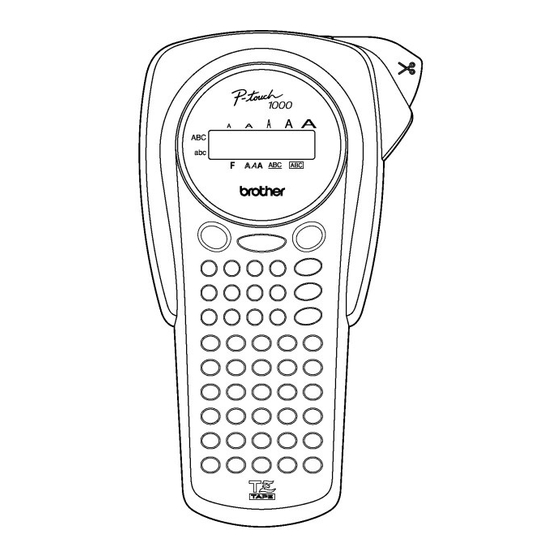
CHAPTER I SPECIFICATIONS Mechanical Specifications 1.1.1 External Appearance Figure 1.1-1 External Appearance (1) Dimensions (W x D x H) 108 x 196 x 55 mm (4.3 x 7.7 x 2.2 inches) (excl. keys, cutter lever and bottom feet) (2) Weight Machine proper Approx. -
Page 6: Printing Mechanism
1.1.4 Printing Mechanism (1) Print system Thermal transfer onto plastic and fabric tapes (Fixed thermal print head and tape feed mechanism) (2) Print speed 10 mm/second (3) Print head Type Thermal print head Heat generator Consists of 64 heating elements vertically aligned in 180 dpi Size of a heating element 0.195 mm wide by 0.141 mm high... - Page 7 USA version Figure 1.1-2 (1) Display and Key Arrangement I - 3...
- Page 8 EUROPE version Figure 1.1-2 (2) Display and Key Arrangement I - 4...
- Page 9 UK version (GL-100) Figure 1.1-2 (3) Display and Key Arrangement I - 5...
-
Page 10: Electronics Specifications
Electronics Specifications 1.2.1 Character Generator (1) Internal characters (2) Internal fonts HELSINKI and OKLAHOMA (3) Text buffer Max. 55 characters (4) File memory Max. 300 characters (5) Memory backup No dedicated backup battery is provided. However, the memory is backed up for 5 minutes even after: 1) you remove the dry cells (e.g., at the replacement time of dry cells) without connection of the optional AC adapter. -
Page 11: Key Commands For Special Functions
Key Commands for Special Functions 1.3.1 Initializing When the machine power is off, pressing the key with both the Function and R keys held down initializes the machine. When releasing those keys, be sure to first release the key and then release the Function and R keys. I - 7... -
Page 12: Chapter Ii Theory Of Operation
CHAPTER II THEORY OF OPERATION Outline of Mechanisms 2.1.1 Print Mechanism Structure of Thermal Head This machine uses direct thermal printing. The thermal print head has a heat generator consisting of 64 heating elements which are vertically aligned in 180 dpi as shown in Figure 2.1-1. -
Page 13: Roller Holder Assy Setting & Retracting Mechanism
2.1.2 Roller Holder ASSY Setting & Retracting Mechanism This mechanism consists of the roller holder ASSY and the holder cam (provided on the cassette cover ASSY). The cassette cover has a holder cam on the inside. Closing the cassette cover causes its holder cam to press section A of the roller holder ASSY as shown below. - Page 14 The roller holder ASSY supports the platen roller and tape feed sub roller so that they can move perpendicularly to the thermal head and tape feed roller built in a tape cassette, respectively, as well as rotating freely. Closing the cassette cover presses the platen roller perpendicularly against the thermal head with the tape and ink ribbon sandwiched inbetween under a uniform load by the upper and lower roller holder springs.
-
Page 15: Tape & Ribbon Feed Mechanism
2.1.3 Tape & Ribbon Feed Mechanism This mechanism consists of a drive motor (DC motor), gear train, and roller holder ASSY. n Tape Feeding As the drive motor rotates, the rotation is transmitted via the gear train to the platen idle gear (which rotates the platen gear) and tape idle gear (which rotate the tape feed roller and its sub roller at the same rotation speed). - Page 16 n Adhesive Base Tape Feeding (only for laminate tape cassettes) A laminate tape cassette contains both a transparent laminate tape roll and a separate adhesive base tape roll. When a transparent laminate tape and adhesive base tape pass through the contact point (between the tape feed roller and tape feed sub roller), they are then bonded together into a single, printed tape.
-
Page 17: Tape Cutter Mechanism
2.1.4 Tape Cutter Mechanism The tape cutter ASSY consists of a cutter case ASSY and cutter board. Pressing the cutter lever pushes out the cutter blade against the cutter board, cutting the printed tape coming through the cutter case ASSY and cutter board. Figure 2.1-7 Tape Cutter Mechanism II - 6... -
Page 18: Cutter Safety Lock Mechanism
2.1.5 Cutter Safety Lock Mechanism When the cassette cover is opened and no tape cassette is loaded, the roller holder ASSY is retracted from the thermal head with the roller holder release spring (as described in Section 2.1.2). In this retracted position, the cutter lever stopper of the roller holder ASSY blocks the end of the cutter lever, preventing the cutter blade from getting driven for safety, as shown below. -
Page 19: Cutter Jam Prevention Mechanism
2.1.6 Cutter Jam Prevention Mechanism When the machine is printing or feeding tape, pressing the cutter lever turns on the cutter sensor switch via the cutter sensor arm and immediately stops the DC motor. This prevents the cutter blade from interrupting the tape being fed and causing a tape jam. Figure 2.1-10 Cutter Jam Prevention Mechanism II - 8... -
Page 20: Outline Of Control Electronics
Outline of Control Electronics 2.2.1 Configuration Figure 2.2-1 shows a block diagram of the control electronics of this machine. The control electronics consists of two PCBs (main PCB and key PCB), an LCD, motor, thermal print head, tape cassette sensor (switch ASSY) and cutter sensor. n Main PCB This PCB manages all the components including an LCD, motor and thermal print head. - Page 21 Figure 2.2-1 Configuration of the Electronic Part II - 10...
-
Page 22: Main Pcb
2.2.2 Main PCB [ 1 ] Block Diagram Figure 2.2-2 shows a block diagram of the main PCB. The main PCB consists of the following: DC motor driver Thermal head driver Oscillation circuit Solder points Power supply circuit Key detector circuit Voltage detector circuit Temperature sensor detector (10) LCD driver... -
Page 23: 2 ] Solder Points
[ 2 ] Solder Points This machine has five solder points--1 through 3, A and C. n Destination Solder points 1 through 3 customize the machine for destination. as listed in Table 2.2-1. Table 2.2-1 Destination Solder points Destination High High High EUROPE/USA... -
Page 24: 3 ] Identification Of Tape Cassette Type
[ 3 ] Identification of Tape Cassette Type The cassette sensor (Switch ASSY) has three sensor switches (SW2, SW3 and SW7). Loading a tape cassette turns on some of those switches while keeping others off depending upon the ID encoding holes provided in the tape cassette currently loaded. If an encoding ID hole is closed, the corresponding sensor switch goes on. -
Page 25: Chapter Iii Disassembly & Reassembly
CHAPTER III DISASSEMBLY & REASSEMBLY n Safety Precautions (1) You should carry out disassembly & reassembly jobs on an anti-static sheet grounded correctly. Otherwise, the LSI and other electronic devices will be damaged due to the electricity charged in your body. (2) When transporting PCBs, be sure to wrap them in conductive sheets such as aluminum foil. -
Page 26: Disassembly/Reassembly
Disassembly/Reassembly [ 1 ] Removing the Cassette Cover, Tape Cassette, and Dry Cells (1) Turn the machine upside down. (2) Press section "A" of the cassette cover to release the latch, then remove the cassette cover. Figure 3.1-1 Removing the Cassette Cover (3) Remove the tape cassette and six dry cells. -
Page 27: 2 ] Removing The Cutter Case Assy And Cutter Board And Separating The Bottom Cover From The Upper Cover
[ 2 ] Removing the Cutter Case ASSY and Cutter Board and Separating the Bottom Cover from the Upper Cover (1) Pull out the cutter case ASSY and cutter board. (2) Remove the five screws from the bottom cover. Figure 3.1-3 Removing the Cutter Case ASSY, Cutter Board and Screws from the Bottom Cover (3) Discharge the capacitor mounted on the main PCB by touching both the + and - terminals (of the main PCB ASSY) with a tweezers. - Page 28 Figure 3.1-4 Separating the Bottom Cover from the Upper Cover III -...
- Page 29 n Reassembling notes • When setting the cutter sensor arm and its spring back to the upper cover, first insert spring end "x" into the hole provided in the cutter sensor arm and then fit them over the pivot shaft as shown in Figure 3.1-4. Check that the cutter sensor arm moves smoothly. •...
-
Page 30: 3 ] Removing The Frame Assy And Cutter Lever
[ 3 ] Removing the Frame ASSY and Cutter Lever (1) Unsolder the two motor leads from the main PCB. (2) Remove the three screws from the frame ASSY. (3) Take the frame ASSY up and out of the bottom cover. The cutter lever also comes off. - Page 31 Disassembling the Frame ASSY 1) DC motor ASSY Remove the two screws and take the DC motor ASSY off the frame ASSY. Figure 3.1-7 Removing the DC Motor ASSY 2) Roller holder ASSY Remove the retaining ring and pull out the roller holder ASSY together with its release spring.
- Page 32 3) Head ASSY CAUTION: Before handling the head ASSY, take care not to touch it directly by hand. The head ASSY may be damaged due to the static electricity charged in your body. Remove the screw and take the head ASSY off the frame ASSY. Figure 3.1-9 Removing the Head ASSY n Reassembling notes •...
-
Page 33: 4 ] Removing The Terminal Press Cover And Releasing The - Terminal Assy
[ 4 ] Removing the Terminal Press Cover and Releasing the - Terminal ASSY (1) Turn the bottom cover upside down. (2) Press the two latches on the terminal press cover inwards with the tip of a flat screwdriver and push down the terminal press cover. (3) Release the - terminal ASSY from the terminal press cover. -
Page 34: 5 ] Removing The Battery Terminals B And Releasing The + Terminal Assy
[ 5 ] Removing the Battery Terminals B and Releasing the + Terminal ASSY (1) Remove two battery terminals B from the bottom cover. (2) Unlatch the locking pawl of the + terminal ASSY with the tip of a flat screwdriver and release it from the bottom cover. -
Page 35: 6 ] Removing The Battery Terminals A
[ 6 ] Removing the Battery Terminals A (1) Press the locking pawl on each of three battery terminals A and push down each terminal A with the tip of a flat screwdriver. Figure 3.1-12 Removing the Battery Terminals A n Reassembling notes •... -
Page 36: 7 ] Removing The Switch Assy, Cutter Sensor Assy And Main Pcb Assy
[ 7 ] Removing the Switch ASSY, Cutter Sensor ASSY and Main PCB ASSY CAUTION: When handling the PCBs, put on a grounding wrist band. Failure to do so might break LSIs and other electronic devices. (1) Unsolder the four switch ASSY leads from the main PCB. (2) Release the SW holder plate by removing the screw. -
Page 37: 8 ] Removing The Rubber 49 Key
[ 8 ] Removing the Rubber 49 Key (1) Lift the rubber 49 key up and out of the upper cover. Figure 3.1-14 Removing the Rubber 49 Key n Reassembling notes • Make sure that the rubber 49 key is fitted over the two positioning bosses and two positioning pins. -
Page 38: Final Check And Inspection Mode
Final Check and Inspection Mode n After completion of reassembling (1) Check that each rubber key works correctly with light touch. (2) Check that the cutter lever works smoothly. (3) To initialize the internal memory, press the key with both the Function and R keys held down. - Page 39 Destination Source voltage Head rank Destination If the destination is Germany, for example, "GE" will appear on the LCD. (The destination is determined by solder points 1 through 3.) Solder points The LCD Destination shows: High High High EUROPE/USA (Open) (Open) (Open) Head rank...
- Page 40 2) Press the key. LCD check screen 1 will appear as shown below. (All guidance indicators and cursors: OFF) Press the key. LCD check screen 2 will appear as shown below. (All guidance indicators and cursors: ON) Press the key. LCD check screen 3 will appear as shown below.
- Page 41 KEY submode (3 key*) (*You may switch back to this KEY submode from any other submode by pressing the 3 key.) With LCD check screen 3 displayed, press the key. The machine displays "KEY" and enters the KEY submode. Press the key to start checking keys.
- Page 42 CUT submode (4 key*) (*You may switch back to this CUT submode from any other submode by pressing the 4 key, except during the key depressing test in the KEY submode.) NOTE: You may skip this submode since you may check the tape cutter in any other submode.
- Page 43 PRINT1 submode (5 key*) (*You may switch back to this PRINT1 submode from any other submode by pressing the 5 key, except during the key depressing test in the KEY submode.) With the "PRN1" displayed, the machine is in the PRINT1 submode. Press the key.
-
Page 44: Chapter Iv Troubleshooting
CHAPTER IV TROUBLESHOOTING This section gives the service personnel some of the troubleshooting procedures to be followed if an error or malfunction occurs with this machine. It is impossible to anticipate all of the possible troubles which may occur in future and determine the troubleshooting procedures, so this chapter covers some sample troubles. -
Page 45: Troubleshooting Flows
Troubleshooting Flows [ 1 ] Tape feeding failure IV - 2... - Page 46 IV - 3...
-
Page 47: 2 ] Printing Failure
[ 2 ] Printing failure IV - 4... - Page 48 IV - 5...
-
Page 49: 3 ] Powering Failure (Nothing Appears On The Lcd.)
[ 3 ] Powering failure (Nothing appears on the LCD.) IV - 6... -
Page 50: 4 ] No Key Entry Possible
[ 4 ] No key entry possible IV - 7... -
Page 51: 5 ] Tape Cassette Type Not Identified
[ 5 ] Tape cassette type not identified IV - 8... -
Page 52: Appendix A Main Pcb Circuit Diagram
Appendix A. Main PCB Circuit Diagram MAIN PCB CIRCUIT NAME DIAGRAM PT1000 CODE LN6004001 : Ceramic capacitor... -
Page 53: Appendix B Key Pcb Circuit Diagram
Appendix B. Key PCB Circuit Diagram (Period) (Comma) Battery terminal Chip Battery terminal Black (Close the power feeding circuit) KEY PCB CIRCUIT NAME DIAGRAM PT1000 : Ceramic capacitor CODE LN6046001 : Electrolytic capacitor... - Page 54 Apr. 2004 8V2056BE0 Printed in Japan...
Need help?
Do you have a question about the PT-1050 and is the answer not in the manual?
Questions and answers