
Related Manuals for LELY WELGER RP 202 CLASSIC


Summary of Contents for LELY WELGER RP 202 CLASSIC
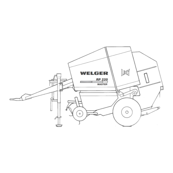
- Page 1 RP 202 / RP 302 RP 220 / RP 320 WELGER RP 220 MASTER 1742-85 Operating Manual from year of manufacture 2000 1742.99.03.04 03.00...
- Page 2 Reproduction prohibited - all rights reserved. Design and construction subject to alterations. The illustrations shown are non-binding for model, form and equipment. 2000 by Lely Welger Maschinenfabrik GmbH, Wolfenbüttel. Made in Germany. Lely Welger Maschinenfabrik GmbH Manufacturer: Postfach 1965 •...
- Page 3 Handover Declaration Please fill in this form when the machine is handed over and return it to the distributor. No warranty applications can be processed until this form is received. (1) Handover Date (2) Type: Machine No.: (see data plate: #) Equipment fitted: Pick-up unit 1.50 m Pick-up unit 2.00 m...
-
Page 5: Model Overview
1. Model Overview This Operating Manual describes the models RP 202, RP 220, RP 302 and RP 320 • 1,50 m 2,00 m • (Feeder) 2,00 m • • • (annular-tubed rotor) • • 2,25 m MASTERCUT 12 blade PROFICUT •... - Page 6 2. Your Safety • All the protective devices such as the safety covers, rubber aprons or safety brackets are provided for your safety! Never operate the baler with defective safety devices or if the safety devices have been removed! • Always keep components which are relevant to safety in a suitable condition. All guards must be fitted and closed before putting the baler into operation! •...
- Page 7 2.2. Fire prevention • Crop materials are very combustible. • Always keep the baler free of crop remnants and oil contamination. • Should overheating of the baler components occur, determine the cause and resolve accordingly. • Always keep the electrical circuits of the tractor and baler, as well as the tractor’s exhaust system in perfect working order.
- Page 8 2.4. Hydraulic system Max. operating pressure of the hydraulic system • 210 bar When carrying out assembly work on the hydraulic system, particularly when using accumulators (fig. 4): • Depressurise the hydraulic system (control valve set to “Lower”) • Mechanically secure hydraulically operated...
- Page 9 2.6. Warning symbols 2.6.1. Explanation of the symbols Danger areas which cannot be made safe by design measures are identified by yellow warning symbols. Since these are signs without texts in most cases, their precise meaning is described below. The warning symbols must always be kept in a recognizable state.
- Page 10 Switch off the engine and pull out the plug from the power supply before starting any repair, maintenance and cleaning work. Spare part No.: 0388.13.00.00 Stay clear of tailgate swinging area while in operation. Spare part No.: 0389.93.00.00 Do not ride on platform or ladder. Spare part No.: 0391.06.00.00 Handle the cutting unit blades only if you are wearing gloves and using suitable tools.
- Page 11 2.6.2. Where to locate the warning signs 0389.92.00.00 0388.11.00.00 0388.25.00.00 0388.37.00.00 0388.24.00.00 0389.92.00.00 0389.92.00.00 0391.06.00.00 0388.13.00.00 0389.94.00.00 0389.94.00.00 0387.33.00.00 0387.37.00.00 0387.34.00.00 0387.34.00.00 0389.93.00.00 1742-73 fig. 7 WELGER RP 202 • RP 220 • RP 302 • RP 320...
- Page 12 2.7. Symbols for the operation of the baler The most important operating instructions are shown as symbols for the purpose of clarity. The exact descriptions are given below. Symbol Description/Spare part No. The two lifting eyes in the upper part of the baler are identified by this symbol.
- Page 13 2.8. Proper Use • The baler has been built exclusively for producing bales compressed from agricultural straw material lying on the ground (proper use). Usage beyond this does not constitute proper use. The manufacturer is not liable for damage resulting from improper use; the user alone bears the risk. •...
- Page 14 2.10. Precautions for driving on the road Before driving on the road ... … the baling chamber must be completely emptied (in accordance with Road Traffic Vehicle Registration Regulations (RTVRR); … the baler must be cleared of any harvested crop attached to …...
- Page 15 Ident - Nr. max. Ges. Gewicht/Gross Weight max. Stützlast/Imposed Load max. Achslast/Axle Load Höchstgeschw./max. Speed Baujahr/Year of Manufacture Lely Welger Maschinenfabrik GmbH • Gebrüder-Welger-Str. 3 D - 38304 Wolfenbüttel • Made in Germany 1742-70 fig. 8 Item Meaning ID number – individual machine number. Always quote in the event of queries Permissible total weight for operation on public roads.
- Page 16 3. Component Overview 12 V fig. 9 Component Component Pick up unit Net wrapping* BALERCONTROL III - Control panel* Bale ejector* BALERCONTROL E - Control panel* Tailgate Cutting device* Lock Floor flap* Chain wheels for roller drive Twine wrapping* WELGER RP 202 • RP 220 • RP 302 • RP 320...
- Page 17 4. Putting Into Operation When handling parts of the machine in the area of the drawbar, make sure that the machine is safeguarded from rolling away. Do not crank up the support foot until the baler is securely coupled to the tractor. Do not disconnect the baler until: •...
-
Page 18: Table Of Contents
4.1.1. Drawbar configuration (all dimensions in [mm]) C - 5 A - 1 B - 5 A - 2 B - 6 A - 3 8 7 6 5 B - 7 A - 4 RP 202 B - 8 fig. - Page 19 RP 220 RP 320 fig. 12 4.1.2. Adjusting the trailer hitch Any adjustment in the height set-up, and therefore a displacement in the drawbar eye position, shall only be carried out by the manufacturer or an approved specialist workshop. • Position the baler on even ground. •...
- Page 20 Important: Depending on the equipment configuration, a rigid 1725-159 or rotatable drawbar eye can be fitted. (observe local regulations!) The drawbar eye [3] can be rotated about its longitudinal axis, but has to be locked for a open-type hitch attachment For open-type hitch (high hitch) attachment, prevent drawbar eye [3] from turning by fitting parts 4, 5 and 6.
- Page 21 4.1.3. Configuration of the tow hitch 1246-154 If the baler is attached to the tractor tow hitch, compliance with the following dimensions is necessary: (Table 3). Tow hitches other than as shown in Figure 17 and Table . are not permitted!Danger of breakage! fig.
- Page 22 4.2. Universal drive shaft 4.2.1. Connecting the cam-type cut-out clutch* Depending on the model, the universal drive shaft is fitted with an automatic overload safety cut out (cam-type cut-out clutch). • Clean and grease the splines of the connecting shaft before installation.
- Page 23 4.2.3. Adjusting the universal drive shaft Pay attention to the maximum operating length L Lmin 1246-162 minimum operating length L Aim for the greatest possible min! overlap. a) Shortest operating length, i.e., fully covered 2/3 LU b) During normal operation, the overlap of the tube section should be at least 2/3 of the overlap L Lmax c) The universal drive shaft can be operated with length L...
- Page 24 4.3. Hydraulic hoses Symbol on hydraulic hose Baler Function Tractor Colour connection identification Open and close tailgate single-acting yellow RP 202 RP 220 RP 302 RP 320 Raise and lower pick up single-acting RP 202 RP 220 w/o CD RP 302 RP 320 w/o CD RP 220 Activate floor flap and...
- Page 25 Clean the coupling parts of the hydraulic pipes with a clean cloth and plug in to the sockets at the tractor. Check hoses and pipelines regularly for damage, deterioration and safe functioning. Defective parts are to be replaced immediately by original WELGER replacement parts. Hoses and hose lines are subject to natural deterioration even under normal operating loads.
- Page 26 5. Twine wrapping* 5.1. Threading the baling twine Insert and thread new twine spools only when the baler is switched off. Remove the ignition key Use good quality baler twine. Refer to technical data at the end of this operating manual. The use of plastic twine is recommended.
- Page 27 Threading-in diagram for machines with BALERCONTROL “E” RP 202 / RP 302 CLASSIC and SPECIAL RP 220 / RP 320 FARMER fig. 26 Threading-in diagram for machines with „BALERCONTROL III” RP 220 / RP 320 MASTER / PROFI / SPEEDMASTER / SPEEDPROFI fig.
- Page 28 5.1.1. Cross Support 1. Guide twines A and B through to the guide rollers [8] as shown in fig. 28. 2. Loop twine A anticlockwise once around the variable diameter disc [9]. 3. Finally locate each twine at the entry to their respective guide roller.
- Page 29 5.1.2. Setting the twine brake Spring length at the twine brake (fig. 29) Basic set up BALERCONTROL E BALERCONTROL III (fig. 26) (fig. 27) Twine A 39 mm 33 mm (shown as continuous line ) Twine B 37 mm 28 mm (shown as dashed line - - - - - - ) The twines brakes [1] (fig.
- Page 30 5.1.3. Setting the edge clearances In order to limit the twine wrapping on the ends of the roll bale, the edge clearance retainers [1] are adjustable (the right side of the baler is shown in fig 30 and fig. 31, but the same applies to the left side):With very dry and brittle crops it is better if the retainers are located more towards the middle of the baler.
- Page 31 6. Net Wrapping* 6.1. Inserting the net In order to handle the net roll safely, insert it together with the help of a second person! • Open all protective covers. • First place the net roll at an angle over both net roll recesses from the left side (Fig.
- Page 32 1721-111 fig. 36 • Guide the net from the roll around the upper deflection roller [4] and finally around the net tensioner [3]. • Place the beginning of the net over the sideways tensioner [5] and then between the rubber roller [6] and steel roller [7]. •...
- Page 33 6.2. Tensioning the net cutting knife The net cutting knife is automatically tensioned (reset) each time the tailgate is opened. If a new net wrapping is required without opening the tailgate while the bale chamber is full, due to a net changeover or fault, the tensioning process can be done manually.
- Page 34 7. Cutting Device* RP 220 • RP 320 Depending on the model, the baler can be fitted with a 12-blade cutting device (MASTERCUT) or with a 23-blade cutting device (PROFICUT). It can be used for silage, hay and straw. The cutting device is hydraulically moved in and out.
- Page 35 RP 220 FARMER - RP 320 FARMER with cutting unit and swivel floor Activating the cutting device: 1. Open the shut-off valve on the left side of the baler (fig. 43), i.e. move the lever into the vertical position. 2. Activate the "raise" function on the connected tractor valve until the cutting device moves into its working position.
- Page 36 Hydraulic protection of the cutter blades Note: The cutting device is safeguarded from being overloaded by a single hydraulic pressure switch serving the cutter blades. This activates at a factory set pressure limit. This is also the pressure available for moving in the blades. Depending on the situation, the hydraulic pressure may not necessarily suffice if the blade grooves are blocked.
- Page 37 RP 220 FARMER • RP 320 FARMER with cutting unit and without swivel floor The cutting device is directly actuated with the double-acting tractor control valve. (The actuating direction can be changed by swapping the connected hydraulic hoses.) In order to ensure free movement of the individual blades, it is recommended to move the cutting device in and out several times each day.
- Page 38 7.2. Brittle crops It is recommended when baling brittle crops to hydraulically move the cutting device out of the cutting position before wrapping. The bales are then enclosed by long material and crumbling losses are avoided to a large extent. 7.3.
- Page 39 7.4. Sharpening the cutter blades In order to ensure an optimum throughput of crops, it is recommended that the cutter blades be sharpened after 500 bales have been cut at the latest. Depending on the operating conditions, sharpening may also be required sooner. As described above, remove the blades and grind the cutting edge from the smooth side.
- Page 40 8. Field Use The roll baler is safeguarded against foreseeable accidents. In spite of this, necessary precautions must still be taken when working. Each time before use, check that all safety devices on the roll baler are in proper working order. Never attempt to correct malfunctions while the machine is in operation.
- Page 41 8.4. Pick-up unit RP 202 • RP 302 CLASSIC / SPECIAL RP 220 • RP 320 FARMER The pick-up unit is raised and lowered by operating the tractor control valve. RP 220 • RP 320 MASTER / PROFI / SPEEDMASTER / SPEEDPROFI An electro-hydraulic manifold block (Hydraulic switch*) makes it possible to operate a number of different hydraulic functions with a single control valve.
- Page 42 Special Notes: 1742-42 RP 202 CLASSIC / RP 302 CLASSIC Pick-up unit width 1.50 m (fig. 56) As an optional feature, a pick-up unit short crop guard can be supplied (not shown).
- Page 43 8.5. Feed guide plate The streamlined feed guide plate [1] is factory installed in the roll 1742-51 chamber. Should material become jammed due to unusual crop conditions, then the feed guide plate may be removed. To do this, take out screws (arrow in fig. 59) on the right side (in the driving direction) and remove the plate from the roll chamber.
- Page 44 8.8. Setting the bale density RP 202 • RP 302 CLASSIC / SPECIAL RP 220 • RP 320 FARMER There is a lever on the right-hand side of the baler to set the density. 1. With the side panel open, loosen the wing nut. 2.
- Page 45 8.9. Locking the tailgate Before picking up the crop and after each bale ejection, the tailgate must be locked properly. To do this, keep the tractor control valve for tailgate actuation in the "lower" position. This will automatically lock the tailgate. For balers with net wrapping, the tractor control valve must be kept in the "lower"...
- Page 46 9. Wrapping The following wrapping modes* can be selected • manual wrapping (twine and net) • automatic twine wrapping • automatic net wrapping • manual combined wrapping • automatic combined wrapping (only for MASTER and PROFI) 9.1. "BALERCONTROL E Control Panel“ RP 202 •...
- Page 47 9.1.1. Triggering the wrapping (BALERCONTROL E) When the pre-selected bale density is reached, the tractor driver is notified by the red LED [2] and the buzzer [9]. Depending on the selected wrapping mode, the wrapping is triggered either automatically or manually from the appropriate button (net [6] or twine [7]).
- Page 48 Automatic twine wrapping • Selection: Depress button [5] (fig. 62) several times until the right yellow LED lights up. • Once the pre-selected bale density is reached, the red LED initially begins to flash and then remains continually on. • The twine is automatically guided into the roll chamber.
- Page 49 Combined net / twine wrapping In order to minimise crumbling losses and keep net consumption low, it is possible to use both types of wrapping simultaneously. • Activate the baler for automatic twine wrapping (see page 44). • Allow the twine wrapping to be triggered automatically. •...
- Page 50 9.2.1. Wrapping the bale Repeatedly depress the button <AUTO/MAN> on the control panel until the desired wrapping type is selected. The following sequence appears: Set to: manual wrapping (twine and net possible) PU Man Cut 4(4) Set to: automatic twine wrapping PU Twine Cut 4(4) Set to: automatic net wrapping...
- Page 51 9.2.2. Twine wrapping, 9.2.3. Net wrapping, 9.2.4. Twine wrapping, manually triggered: manually triggered: automatically triggered: Audible (3 sec.) and visual Audible (3 sec.) and visual Wrapping starts without any signal when reaching the signal when reaching the action from the driver on selected baling density (visual: selected baling density (visual: reaching the pre-selected...
- Page 52 9.2.5. Net wrapping, 9.2.6. Combined wrapping, 9.2.7. Multiple triggering of automatically triggered: automatically triggered: the wrapping: Wrapping starts without any "automatic twine Automatic wrapping can only action from the driver on wrapping" and the "automatic triggered once. reaching pre-selected wrapping" started reactivate, the tailgate must be baling density.
- Page 53 9.3. Ejecting the bale After completing the wrapping process, open the tailgate hydraulically so that the bale rolls out. Keep the tractor control valve on "raise" until the tailgate has completely opened. If no bale ejector* (see fig. 9, No. 8) is fitted, then reverse by approx.
- Page 54 10. Overload protection / Reversing mechanism 10.1. Universal drive shaft with shearing bolt clutch* A shearing bolt clutch is installed in the universal drive shaft on the baler side. In the event of overloading, the bolt [1] will shear and must be subsequently replaced by a new one. Only put the machine into operation again when the cause for the overload has been resolved.
- Page 55 10.4. Reversing the pick-up unit RP 202 / RP 302 SPECIAL For blockages in the inlet section, the pick-up unit drive can be manually rotated backwards (see fig. 69): • Switch off the pto shaft • Switch off engine and remove the ignition key •...
- Page 56 10.5. Hydraulic bottom flap* (HYDROFLEXCONTROL)* The hydraulically hinged conveyor channel floor has two hydraulic cylinders which help in extending the conveyor channel through to the roll chamber. Any congested material is thereby easily pulled through, grasped by the lower pressing roller and transported into the roll chamber.
- Page 57 11. "BALERCONTROL"* Not only the control unit (only with BALERCNTROL III), but also the operating control panel, as well as the associated program, all have their own serial numbers. In order to process future enquiries, it is necessary to state the serial / version numbers.
-
Page 58: Your Safety
11.1. Your Safety The "Balercontrol" control system was designed and manufactured with utmost attention to details and maximum precision. Each unit has been checked and tested for correct functioning before delivery. Despite all the precautions, a malfunction can still occur. Therefore, the "Balercontrol" control system and associated baler should be always operated in such a manner that prevents damage to person or property. - Page 59 11.3. The "BALERCONTROL III" Control Panel RP 220 • RP 320 MASTER / PROFI / SPEEDMASTER / SPEEDPROFI Important baler functions can be controlled and monitored with the control panel remotely from the tractor. The control panel (fig. 71) consists of: •...
- Page 60 11.4. Menu structure Functions that are often used during normal baling can be directly operated by pressing the appropriate button on the keypad. (fig. 73). keep button depressed Menu structure BALERCONTROL III RP 220 • RP 320 Balercontrol Balercontrol '95 PU Twine Cut MASTER / PROFI / SPEEDMASTER /...
- Page 61 1724-45 hold down Mode Indication circulates PU Twine CUT Mode: Bottom 2 (4) Monitor Mode Mode 3 sec. Mode 3 sec. 3 sec. 1x short 1x short Mode: release Maschinery type Language: Delay Setup Mode RP 320 w.. MC English Mode 2,5 sec.
- Page 62 11.5. Instruction sequence Change bale Operate Operate pick up Operate density: Bottom flap*: up/down Cutting device*: PU Twine PU Twine BD Twine PU Twine 2 (4) 2 (4) 2 (4) Bottom Press briefly once Press briefly once Press briefly once Bale density Pre-set PU Twine...
- Page 63 Change Reset daily Read Read daily language: counter: life time counter counter: Press briefly once Press briefly once Press briefly once keep pressed: TAZ= 000235 B Mode: DLC= 000235 B TAZ= 000235 B Setup release button: Daily counter (DLC) = 235 Bales Depress simultaneously Press briefly once for 3 sec...
- Page 64 Set machinery Read Read wrapping Change type: machinery type: delay: wrapping delay: keep pressed: keep pressed: keep pressed: keep pressed: Mode: Mode: Mode: Mode: Setup Setup Setup Monitor release button: release button: release button: release button: Language: Language: Language: Language: English English English...
- Page 65 Diagnosis Diagnosis Diagnosis Diagnosis Acutator: Voltage: Sensor: Analog Sensor keep pressed: keep pressed: keep pressed: keep pressed: Mode: Mode: Mode: Mode: Diagnosis Diagnosis Diagnosis Diagnosis release button: release button: release button: release button: Diag Sensor Diag Sensor Diag Sensor Diag Sensor Netg.bld.
- Page 66 Diagnosis Diagnosis Diagnosis sensors actuators voltage (automatic): (automatic): (automatic): keep pressed: keep pressed: keep pressed: Mode: Mode: Mode: Diagnosis Diagnosis Diagnosis release button: release button: release button: Diag Sensor Diag Sensor Diag Sensor Netg.bld. xx I Netg.bld. xx I Netg.bld. xx I Press briefly once Press briefly once...
- Page 67 Select wrapping Read serial Read software unit: number: version: keep pressed: keep pressed: PU Twine 2 (4) Automatic twine wrapping Mode: Mode: Systeminfo Systeminfo Press briefly once release button: release button: Serial number Serial number: PU Net 127002 127002 2 (4) Automatic net wrapping 3 sec.
- Page 68 WELGER RP 202 • RP 220 • RP 302 • RP 320...
- Page 69 12. Maintenance / Settings 12.1. General instructions After about the first 20 operating hours, tighten all screws and nuts, including those inside the machine. When doing so, do not change adjustment screws, e.g. on the twine guide or the net brake.
- Page 70 Setting the oscillation damper The motion of the net tensioner [12] is braked with an oscillation damper on the left side of the baler. Two wing nuts (arrows in fig. 76) press the friction pads against the net tensioner from both sides. To set the net tensioner, first of all move it into its highest position and do up the wing nut "finger-tight".
- Page 71 12.4. Balercontrol components RP 220 • RP 320 MASTER / PROFI / SPEEDMASTER / SPEEDPROFI BALERCONTROL III RP 220 320 MASTER / PROFI / SPEEDMASTER / SPEEDPROFI 16 A DIN 9680 1742-22 fig.78 Control unit Magnet, net wrapping* (N) Motor, twine wrapping* (G) Sensor cutting device (S) Pressure switch (D) , opener at 35 bar...
- Page 72 12.5. Hydraulic diagrams RP 220 • RP 320 MASTER / PROFI / SPEEDMASTER / SPEEDPROFI Hydraulic switch 0952.58.22.00 0,7 mm Screw valves must be closed Release valve opens at 35 bar Pick up BALER- CONTROL Bottom flap 2x 0953.22.01.00 20 bar closed open Cutting device...
- Page 73 RP 220 FARMER • RP 320 FARMER with cuting unit and without swivel floor Zyl.ø 32/20 - Hub 84 V=0.32 l p=20 bar M18x1.5 M18x1.5 ø3 G1/4" 35 bar ø1.2 M18x1.5 M18x1.5 fig. 80 Note: During baler operation, the changeover valve "U" (fig. 80) must always be fully turned to the left.
- Page 74 RP 220 FARMER • RP 320 FARMER with cuting unit and swivel floor Zyl.ø 32/20 - Hub 84 V=0.32 l p=20 bar M18x1.5 M18x1.5 ø3 G1/4" 0952.60.76.00/ 35 bar ø1.2 M18x1.5 M18x1.5 fig. 81 Note: • During operation, the shut-off valve [1] must be closed, otherwise the floor may lower itself.
- Page 75 12.6. Sensor settings* There are three types of sensors installed: No. Designation RP 220 RP 202 Setting Application RP 302 RP 320 • Cutting Device* MASTER Sensor 0,5 - 2,0 mm PROFI • Bottom flap* M 12 SP. MASTER • Right twine run ∅...
- Page 76 12.7. BALERCONTROL III - Quick check RP 220 • RP 320 MASTER / PROFI / SPEEDMASTER / SPEEDPROFI Step 1 ⇒ Plug in the power supply connector; •..The control panel sounds a bleeps ................•..Display lights up ....................... •..The start-up message appears on the display (fig. 72) ........... •..Monitoring display appears ..................
- Page 77 12.8. Pin-outs of control unit RP 220 • RP 320 MASTER / PROFI / SPEEDMASTER / SPEEDPROFI 12 V Supply - brown or "2" 12 Volt Supply - blue or "1" Magnet Net wrap. - brown or "2" Magnet Net wrap. - blue or "1" Motor twine wrap.
-
Page 78: Twine Wrapping
12.9. Lubrication chart after every 500 bales (or daily) Baler component Lubricant Remark (fig. 82) (Table 4) Universal drive shaft Chain lubrication Right side of baler Tailgate hinge1) Both sides Lubricating manifold*, left front Lubricating manifold*, right front not shown in fig. 82 Lubricating manifold*, left rear Lubricating manifold*, right rear not shown in fig. - Page 79 12.10. Schematic diagram of the lubricating positions jährlich / annual / par an 500 B. 500 B. jährlich / annual / par an fig. 82 Lubricant Trade name, e. g.:. Multi-pupose grease Fuchs Renolit FEP 2 Bechem High-Lub LM 2 EP BP Energrease LS-EP2 Elf Epexa 2 Esso Beacon EP 2...
- Page 80 Never carry out adjustments and repairs, or maintenance and service work on the baler while it is running. Switch off engine and remove the ignition key Wait for the baler to stop. Switch off the pto shaft and disconnect the universal drive shaft from the pto shaft before working on the moving parts of the baler. If maintenance or installation/assembly work is performed with the tailgate open, it is essential to secure the tailgate to prevent it from falling.
- Page 81 12.13. Tyre air pressure RP 202 / RP 220 / RP 302 RP 320 25 km/h 40 km/h 80 km/h 25 km/h 40 km/h 80 km/h Tyre size 11.5/80-15.3 Impl. 8-12 PR 1,7 bar 2,7 bar 1,8 bar 2,8 bar 15.0/55-17 Impl.
- Page 82 13. Technical Data RP 202 RP 220 approx. 1.25 x 1.23 approx. 1.25 x 1.23 Roll chamber (∅ x width) [m] Twine wrapping* with a) Hemp twine Running length: 200 or 330 m/kg b) Plastic twine Running length: 400 to 750 m/kg Net wrapping* with Quality roll bale net Length: 2000 or 3000 m / width: max: 1.30 m...
-
Page 83: Net Wrapping
RP 302 RP 320 Roll chamber (∅ x width) [m] approx. 1.50 x 1.23 approx. 1.50 x 1.23 Twine wrapping* with a) Hemp twine Running length: 200 or 330 m/kg b) Plastic twine Running length: 400 to 750 m/kg Net wrapping* with Quality roll bale net Length: 2000 or 3000 m / width: max: 1.30 m Binding material supply... - Page 84 WELGER RP 202 • RP 220 • RP 302 • RP 320...
Need help?
Do you have a question about the RP 202 CLASSIC and is the answer not in the manual?
Questions and answers