Table of Contents
Advertisement
InterMetro Industries Corporation
Wilkes-Barre, PA 18705
1-800-992-1776 www.metro.com
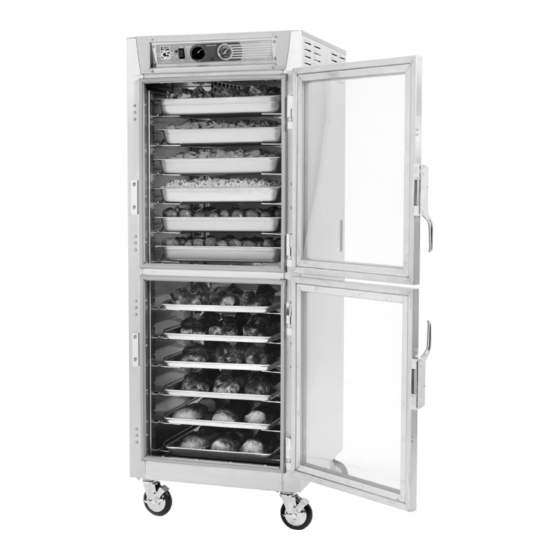
6 Series
Controlled
Temperature
Heated Holding
Cabinets
INSTRUCTIONS
FOR USE
This manual covers cabinets with electrical ratings
of: 120V 2000W, 120V 1440W & 220-240V 1681-2000W.
Metro Heated Cabinets are for
Hot Food Holding applications only
TM
When ordering
electrical parts,
always confirm the
rating listed on rear
cabinet data plate.
Differences on voltage,
amps or wattage are
listed with bold text
in replacement part
descriptions.
L01-427
Rev.G
10/11/17
Advertisement
Table of Contents

Related Manuals for Metro DataVac C5 6 series


Summary of Contents for Metro DataVac C5 6 series
- Page 1 6 Series Controlled Temperature Heated Holding Cabinets INSTRUCTIONS FOR USE This manual covers cabinets with electrical ratings of: 120V 2000W, 120V 1440W & 220-240V 1681-2000W. When ordering electrical parts, always confirm the rating listed on rear cabinet data plate. Differences on voltage, amps or wattage are listed with bold text in replacement part...
- Page 2 1. With the POWER switch OFF, plug the supply power cord into an appropriate, grounded, receptacle. (Refer to the cabinet data plate for voltage and ampere rating). 2. Ensure that the cabinet’s floor duct and water pan are installed. (refer to the cabinet operating instructions). This helps to distribute the heat evenly throughout the cabinet. 3. If extra humidity is desired, fill the water pan in the floor duct of the cabinet with clean warm water. The capacity of the pan is about one quart (one liter). 4. Set the POWER switch to the ON position. The red power light next to the switch will glow when the power is switched ON and will continue to glow until switched OFF. 5. Set the TEMPERATURE control to 6 or 7. This should provide a temperature of 150° to 170°F (66° to 77°C) after allowing the cabinet to preheat for 45 to 60 minutes. 6. The red indicator light between the thermostat and thermometer will turn on and off as the thermostat and heat elements cycle. 7. To change temperature set point, turn the TEMPERATURE control knob. About 30 minutes after a knob is turned, the thermometer should accurately display the change in cabinet temperature. 8. To clean cabinet, turn power off, unplug from wall outlet, allow the cabinet to cool, remove the floor duct and pan, wipe the cabinet with a damp cloth and dry with a towel. 9. Consult the instructions for use for additional operation and maintenance information.
-
Page 3: Table Of Contents
TABLE OF CONTENTS SECTION PAGE I. Basic Operating Guidelines ....Inside Front Cover II. Safety Instructions ..............1 III. Identifying Your Cabinet ............. 2 IV. Installation & Set-up ............. 3 V. Product Features ..............7 VI. Operating Instructions ............8 VII. -
Page 4: Identifying Your Cabinet
IDENTIFYING YOUR CABINET For future reference, note the serial and model number, found on the data plate of the cabinet, here. Model number Serial number Date the cabinet was put into service Fill out and return the warranty card located at the back of this manual. -
Page 5: Installation & Set-Up
INSTALLATION AND SET-UP Check for Shipping Damage: Check the packaging and cabinet for shipping damage after unloading the unit, and after removing all the packaging. The receiver of this product is responsible for filing freight damage claims. This equipment must be opened immediately for inspection. - Page 6 INSTALLATION AND SET-UP (continued) SLIDE INSTALLATION The rack uprights have been installed at the factory. If removed for cleaning, reinstall by hanging them on the shoulder rivets on the side walls of the cabinet. TOP VIEW SLIDE POSITION to MAXIMIZE 3"...
- Page 7 INSTALLATION AND SET-UP (continued) CORRECT ORIENTATION OF LIP LOADED SLIDE RACKS Full Height Full Height Height Height Under Counter Single Door Dutch Doors Cabinet Cabinet Cabinet 2-piece Construction 2-piece Construction 1-piece Construction 1-piece Construction 1-piece Construction Part No. RPC5-L9 Part No. RPC5-L9 Part No.
- Page 8 REVERSING THE DOORS WARNING TIP HAZARD • Tip Hazard: On Pass-Thru cabinets that include any clear doors, when field reversing, the front and back doors must be hinged from opposite sides of the cabinet. See illustration below. Clear Doors Clear Doors Hinged on Hinged on opposite...
-
Page 9: Product Features
PRODUCT FEATURES Control Panel Tray Slides Field Reversible Doors Be careful when opening the doors as hot, humid air will escape Air Duct from cabinet. Flush Water Pan Pull Fill with water. Handles Capacity is (1) quart (1 liter). Floor Duct Holds water pan and evenly distributes air flow. -
Page 10: Operating Instructions
Your C5 6 Series cabinet is capable of creating some humid air. As you operate the cabinet and open and close the door(s), condensation may form on the inside surfaces of the cabinet. Some dripping of water may occur to the outside of the cabinet particularly at the door seals. -
Page 11: Care & Maintenance
If humidity is required, fill the water pan in the bottom of the cabinet. Potable (suitable for drinking) water should be used. Water Pan Fill with water. Capacity is about 1 quart (1 liter). To remove the water from the water pan, allow the cabinet and water to cool and remove the water pan. Note: When turning the cabinet off at the end of the work day, it is recommended to leave the door(s) open to prevent heat and condensation build up within the cabinet. -
Page 12: Basic Troubleshooting
BASIC TROUBLESHOOTING Warning: Only factory approved service agents should attempt to service, repair or replace electrical components, wiring or power cord. 1. Controls do not work (indicator lights): a. Check that the cabinet is plugged in. b. Check that the outlet has power. c. -
Page 13: Service & Replacement Parts
SERVICE and REPLACEMENT PARTS C5 6 SERIES REPLACEMENT PARTS — ELECTRICAL Confirm the cabinet electrical rating before ordering components. Warning: Only factory approved service agents should attempt to service, repair or replace electrical components, wiring or power cord. To access the controller area, remove the (7) screws holding the cabinet top in place. Lift the rear portion of the cabinet top and slide it away from under the front control bezel, removing it from the cabinet. - Page 14 SERVICE and REPLACEMENT PARTS (continued) C5 6 SERIES REPLACEMENT PARTS — CABINET BODY ITEM # Replacement Part No. Description ITEM # Replacement Part No. Description CABINET BODY (continued) CABINET BODY RPC14-042 DOOR HINGE — 1 PIECE RPC06-873B FULL HEIGHT DOOR GASKET B5DNB 5"...
- Page 15 SERVICE and REPLACEMENT PARTS (continued) Replacement Parts Diagram 6 SERIES (Tall Unit Shown) AIR DUCT See page 11. STRAIGHT PLUG CORD SHOWN OR 10A CABINET BODY CONTROL PANEL See page 11. FLOOR DUCT (not shown) *For slide identification, see pages 4 and 5.
- Page 16 SERVICE and REPLACEMENT PARTS (continued) Warning: Only factory approved service agents should attempt to service, repair or replace electrical components, wiring or power cord.
-
Page 17: Warranty
InterMetro Industries Corporation (hereinafter referred to as “Seller”) warrants to the 10/17... -
Page 18: Warranty Information Page
Thank you for purchasing a Metro C5 Controlled Temperature Cabinet. We are certain you will be more than satisfied with its quality and performance. Please fill in the warranty information space below so we may register your warranty. Also, so that we may learn more about our customers and hopefully be of continued service in the future, please take a moment to fill in the customer information space below. - Page 19 STAPLE HERE...
- Page 20 THIS PAGE IS KEPT INTENTIONALLY BLANK...
- Page 21 InterMetro Industries Corporation North Washington Street, Wilkes-Barre, PA 18705 For Product Information Call: 1-800-992-1776 L01-427 Rev. G 10 Visit Our Web Site: www.metro.com Information and specifications are subject to change without notice. Please confirm at time of order.
Need help?
Do you have a question about the C5 6 series and is the answer not in the manual?
Questions and answers