Advertisement
Table of Contents
- 1 Installing the Propellers
- 2 Installing Battery, Binding the Radio, and Extending the Landing Gear
- 3 Compass Calibration
- 4 G-3D 3-Axis Brushless Gimbal Installation
- 5 Motor Unlock
- 6 DEVO F12E- Quick Guide to Control Functions
- 7 Motor Lock
- 8 Operation Instruction
- Download this manual
See also:
Manual
Installing the Propellers
1
1.1 Unpack the propellers, there are two kind
1.2 Match the arrows on the propellers to the
right-hand and left hand rotation, the rotation
arrows on the arm next to each motor. Screw
is identified with arrows on the prop, and also
each propeller onto the motor, secure by hand,
with the colored prop-top. You need 3 of each kind.
no need for tools.
*We recommend balancing the propellers.
Check online for balancing instructions.
Installing Battery, Binding the radio, and extending the landing gear.
2
The Landing gear is shipped in the retracted position. DO NOT try to extend the landing gear by pulling on it.
We will deploy the landing-gear the first time the system is powered, please follow these instructions carefully.
2.1 Install the fully charged battery
2.2 Turn TALI on its back. The belly and the
DO NOT turn on the battery until later.
retractable legs should now be facing up.
*Please check the charger manual for
MAKE SURE nothing is blocking the legs.
charging instructions
Power indicator
Power button
Power switch
2.4 Slide the power-switch to the ON position
2.5 Turn the aircraft to its UP-right position.
then press on the triangle power button
The Red-Green LED flashing will stop shortly.
for about 3-5 seconds, until the green
When it stops, the DEVO F12E and the H500 have
Power indicator lights up.
successfully connected to each other.
* The Landing gear will now unfold automatically.
* This process is called "ID binding"
* In the beginning of this process the light in the
arms flast red-green, this means the system is binding.
Compass Calibration
3
IMPORTANT: Make sure all TRIMs are in the center position, the trim value should be "0", and that the motors are locked.
The aircraft should NOT be flashing RED-GREEN. By default, the motors will automatically be locked after the ID binding process.
For more details about locking and unlocking motors, see points 6 & 7.
3.1 Enter the calibration mode
3.2 FORWARD rotation Rotate tilting the aircraft
Do this by moving both sticks DOWN and
forward rotate smoothly in 90 deg increments.
to the middle position at the same time.
Pausing 1 second for each 90 deg.
The aircraft will start a blinking fast RED-GREEN
(0 / 90 / 180 / 270 / 360)
4
Ground
3.4 HORISONTAL rotation Rotate the aircraft
3.5 NOSE DOWN rotation Rotate the aircraft
around the YAW axis rotate smoothly in 90 deg
facing the nose down. rotate smoothly in 90 deg
increments. Pausing 1 second for each 90 deg.
increments. Pausing 1 second for each 90 deg.
(0 / 90 / 180 / 270 / 360)
(0 / 90 / 180 / 270 / 360)
IMPORTANT: The first couple of flights, you may expereince the aircraft drifting,
This is normal, please continue to fly the aircraft manually, while the system inprove the calibration,
after 5-10 minutes land, lock the motors, this will save the improved settings.
Notice: The slight drifting may continue for a couple of batteries, you will notice significant improvement in the GPShold & stability after 4-5 batteries.
Notice: Always perform the calibration away from eletric fields and metal surfaces.
Trivia: Different brands have different calibration processes, the process is typically refered to as "the Calibration Dance".
4
G-3D 3-axis brushless Gimbal installation
IMPORTANT:
REMOVE the battery from the H500 while you install the gimbal
The gimbal is a high-performance eletromechanical design and should be handled with great care. AVOID using force when installing.
4.1 Unpack the G-3D gimbal,
4.2 Put the rubber washer on the threaded hole on
prepare the gimbal, the mounting
the bottom of the H500, use the M3x8mm and
rail, rubber washer, screws and spring
M3x10mm screws to install the gimbal "mounting
loaded screw.
block" also refered to as the quick mount rail.
4.4 Install the springloaded
4.5 Connect the 9pin white data cable to the "complex
M3x12mm "finger screw" at the front
data port" on the bottom of the TALI, then connect the
of the gimbal, this will secure the gimbal.
cable to the back of the G-3D gimbal.
1.3 After installing the props, check each
propeller carefully.
Before EACH flight, Inspect propellers
for damage.
2.3 On the DEVO F12E, move ALL
switches to the "0" position, and move
the throttle to the lowest position.
Then turn on the DEVO F12E power.
2.6 After the successful binding
place the aircraft on a stable surface.
3.3 CLOCKWISE rotation Rotate the
aircraft around the roll axis rotate smoothly
in 90 deg increments. Pausing 1 second
for each 90 deg. (0 / 90 / 180 / 270 / 360)
Head vertical down
3.6 Place the aircraft in normal position
The rapid RED-GREEN blinking will stop
This indicate that the calibration is finished
Disconnect the battery to save the settings.
4.3 Slide the gimbal unto the quik mount
rail, the gimbal shouldslide from the front
of the aircraft towards the rear, gently
move it as far back as possible.
4.6 Make sure the gimbal move freely
in all directions. The G-3D gimbal is
now successfully installed.
Auto Take off
Altitude hold mode
Object Round fly mode
One key Return To Home
Hyper IOC mode
Retractable Landing Gear
GPS telemetry
5.8G ghz video down link
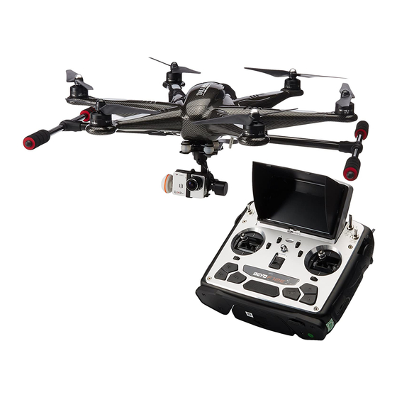
Match with DEVO F12E
Quick Start Guide and Systems Flowchart
Specifications:
M2
Main Rotor Dia. : 233mm
Overall (L x W x H): 471 x 536 x 270mm
M1
Weight: 2020g(Battery included)
Takeoff Weight: <2500g
Transmitter: DEVO F12E
Receiver: DEVO-RX705
Brushless Motor: WK-WS-34-001
Brushless ESC: WST-15AH (R/G)
Main Controller: FCS-H500
Battery: 22.2V 5400mAh Li-Po
M1/M3/M5 rotate in counterclockwise, motors are the dextrogyrate thread.
M2/M4/M6 rotate in clockwise, motors are the levogyrate thread.
5
Installing the iLook+ 1080p camera with 5.8ghz video link
IMPORTANT: NEVER POWER the iLook+ camera without the antenna installed.
Powering a video transmitter may cause damage to the transmitter.
5.1 Screw the short "mushroom" antenna
5.2 Release the two M2x4 screws securing the
into the camera, use the included wrench
camera mounting bracket.
to gently secure the antenna, do not use force.
5.4 Connect the cameras power
5.5 The iLook+ camera is now successfully
cable to the power port on the
installed in your G-3D gimbal.
G-3D gimbal controller.
M4
M3
M6
5.3 Position the camera into the gimbal
"tray", then secure the camera by
positioning the mounting bracket over
the camera, use the two M2x4mm
screws to secure the mounting bracket.
* There is a cutout on the mounting
bracket, this will fit around the lens.
** It is also possible to install a GoPro3
camera in this gimbal. IF you install a
GoPro, unscrew and remove the motor
cover on the pitch motor, this will adjust
the balance of the gimbal for the GoPro.
*** Use the switch on the end of the
iLook+ camera to select between
STILL and 1080p video.
**** You can change the video link
frequency on the back of the camera,
see the instructions included with
the camera for details on camera
operation.
M5
Advertisement
Table of Contents

Related Manuals for Walkera TALI H500


Summary of Contents for Walkera TALI H500
- Page 1 Installing the Propellers Auto Take off Altitude hold mode Object Round fly mode One key Return To Home Hyper IOC mode Retractable Landing Gear 1.1 Unpack the propellers, there are two kind 1.2 Match the arrows on the propellers to the 1.3 After installing the props, check each right-hand and left hand rotation, the rotation arrows on the arm next to each motor.
- Page 2 Landing Gear The TALI H500 will automatically extend the landing gear to protect your camera and make sure the H500 land safely. You can not change the landing gear after the H500 have automatically extended for landing. you must land and lock / unlock motors.
Need help?
Do you have a question about the TALI H500 and is the answer not in the manual?
Questions and answers
How to charge batteries