Table of Contents
Advertisement
Quick Links
Advertisement
Table of Contents

Related Manuals for ABB ACS880-204


Summary of Contents for ABB ACS880-204
- Page 1 ABB industrial drives Hardware manual ACS880-204 IGBT supply modules...
- Page 2 3AUA0000102324 and modules Cabinet design and construction instructions for ACS880 3AUA0000107668 multidrive modules Supply module manuals ACS880-204 IGBT supply modules hardware manual 3AUA0000131525 ACS880 IGBT supply control program firmware manual 3AUA0000131562 ACS880-304 +A003 diode supply modules hardware manual 3AUA0000102452 ACS880-304 +A018 diode supply modules hardware manual...
- Page 3 Hardware manual ACS880-204 IGBT supply modules Table of contents 5. Electrical installation 7. Start-up 2016 ABB Oy. All Rights Reserved. 3AUA0000131525 Rev E EFFECTIVE: 2016-09-22...
-
Page 5: Table Of Contents
Table of contents 1. Introduction to the manual Contents of this chapter ..........15 Applicability . - Page 6 ACS880-204 configurations in Rittal TS 8 enclosures ..... . . 53 ACS880-204 configurations in generic enclosures ......54 IGBT supply unit with frame R1i…R4i module .
- Page 7 Stage 4: DC connection ..........81 Stage 5: Common mode filter busbars and DC connection flanges .
- Page 8 Connection procedure (frame R8i) ........129 Connecting the LCL filter .
- Page 9 Cabinets with ABB air outlet kits ........
- Page 10 DC-side components ..........211 Common DC Flat-PLS assembly .
- Page 11 AC fuses in IGBT supply module cubicle or LCL filter cubicle ....250 Main contactors ..........251 Charging kits .
- Page 12 11. The control units Contents of this chapter ..........291 General .
- Page 13 Providing feedback on ABB manuals ........
-
Page 15: Introduction To The Manual
Introduction to the manual Contents of this chapter This chapter gives basic information on the manual. Applicability The manual is applicable to the ACS880-204 IGBT supply modules for user-defined cabinet installations. Safety instructions Follow all safety instructions delivered with the drive. -
Page 16: Contents Of The Manual
You can find all documentation related to ACS880 multidrive modules on the Internet at https://www151.abb.com/spaces/lvacdrivesengineeringsupport/content. For other manuals, see the inside of the front cover. If needed, contact your local ABB representative. Categorization by frame size and option code The instructions and technical data which concern only certain module or frame sizes are marked with the size identifier. -
Page 17: Terms And Abbreviations
Optional EtherCAT® adapter module FENA-11 Optional high-performance Ethernet/IP™, Modbus/TCP® and PROFINET adapter module FENA-21 Optional high-performance Ethernet/IP, Modbus/TCP and PROFINET adapter module, 2-port (check availability with your local ABB representative) FEPL-01 FEPL-01 Ethernet POWERLINK adapter module FIO-01 Optional digital I/O extension module FIO-11... - Page 18 18 Introduction to the manual Term/Abbreviation Description Frame (size) Refers to power modules that share a similar mechanical construction, for example: • IGBT supply modules of frame R8i • frame 2×R8i includes two size R8i IGBT supply modules. To determine the frame size of a component, refer to the rating tables in chapter Technical data.
- Page 19 Introduction to the manual 19 Term/Abbreviation Description ZCON Type of a control board Type of a control unit (contains ZCON) Type of a memory unit attached to the control unit...
- Page 20 20 Introduction to the manual...
-
Page 21: Operation Principle And Hardware Description
There can be one inverter unit only (single drives) or several inverter units (multidrives) connected to the intermediate circuit. The LCL filter is an essential part of the ACS880-204 IGBT supply module and it does not work without the filter. The IGBT supply module uses the filter to actively shape the AC line current to resemble sinusoidal waveform and to filter most of the current ripple at the switching frequency and higher frequencies. -
Page 22: Simplified Main Circuit Diagram
22 Operation principle and hardware description Simplified main circuit diagram The following figure shows the simplified main circuit diagram of the rectifier. AC fuses LCL filter IGBT supply module DC fuses DC output AC input Charging Charging is always needed to power up the DC link capacitors smoothly. Discharged capacitors can not be connected to the full supply voltage. -
Page 23: Simplified Main Circuit Diagram Of The Drive System
Operation principle and hardware description 23 Simplified main circuit diagram of the drive system The following figure shows a simplified diagram of a common DC bus drive system. Description AC supply Input AC fuses LCL filter IGBT supply unit Supply unit DC fuses DC bus Inverter DC fuses (with or without DC switch-disconnector) Inverter units (in the example, one of the two units consists of two inverter modules connected in... -
Page 24: Single-Line Circuit Diagrams Of The Supply Unit
The following figures are examples of possible IGBT supply unit configurations. The tables give explanations for the numbers and letters of the diagrams. They also indicate if the customer can order the components from ABB or if the customer needs to acquire them separately. For components, see chapter Ordering information. -
Page 25: Frame R6I
The following figure shows a connection example of a supply unit with a frame size R6i module. Cubicle Explanation Available through AC supply network IGBT supply Main switch-disconnector ABB or third party module cubicle (ISU) Charging switch-fuse ABB or third party Charging contactor ABB or third party Charging resistors... -
Page 26: Frame 1×R8I
The following figure shows a connection example of a supply unit with one frame R8i module. Cubicle Explanation Available through AC supply network Incoming Main switch-disconnector ABB or third party cubicle (ICU) AC fuses ABB or third party Charging switch fuse ABB or third party Charging contactor ABB or third party... -
Page 27: Frame R8I Multiples
The following figure shows a connection example of a supply unit with multiple frame R8i modules (2×R8i). Cubicle Explanation Available through AC supply network Incoming Main switch-disconnector ABB or third party cubicle (ICU) AC fuses ABB or third party Charging switch fuse ABB or third party Charging contactor ABB or third party... -
Page 28: Layout Drawings
28 Operation principle and hardware description Layout drawings The following figures show the layout of the IGBT supply modules and LCL filters. IGBT supply module (frames R1i and R2i) Frame R1i is pictured (frame R2i has a similar layout). Item Explanation DC (output) connection (obscured) -
Page 29: Igbt Supply Module (Frames R3I And R4I)
Operation principle and hardware description 29 IGBT supply module (frames R3i and R4i) Frame R4i is pictured (frame R3i has a similar layout). Item Explanation DC (output) connection (under connector cover) AC (input) connection (under connector cover) Grounding/clamping plates for power cables ZCU control unit Power unit Slots for optional I/O modules... -
Page 30: Igbt Supply Module (Frame R6I)
30 Operation principle and hardware description IGBT supply module (frame R6i) Item Explanation DC (output) connection AC (input) connection ZCU control unit (with slots for optional I/O modules) I/O terminal blocks Control panel connector, memory unit Grounding/clamping plates for control cables Cooling fan holder with one fan Lifting eyes... -
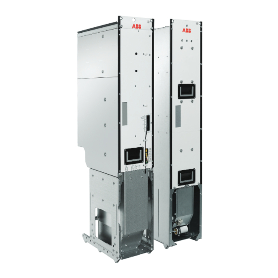
Page 31: Igbt Supply Module (Frame R8I)
Operation principle and hardware description 31 IGBT supply module (frame R8i) Frame R8i modules are used in single or parallel configurations. R8i modules run on wheels, and can easily be removed from the cubicle for cable installation or service. The quick connector at the back of the module couples when the module is inserted into the cubicle. - Page 32 32 Operation principle and hardware description Description ISU module, frame size R8i, front ISU module, frame size R8i, back DC output busbars Handle LEDs (see section LEDs and other status indicators on page 198) Fiber optic connectors (see section Module fiber optic connectors (frame R8i) on page 145) Cooling fan (standard speed-controlled fan shown;...
-
Page 33: Connectors X50
Operation principle and hardware description 33 Connectors X50…X53 The cabinet builder must arrange an auxiliary voltage of 230 V AC (or 115 V AC with option +G304) to connector X50 to power the electronics of the supply module. Also, the cabinet builder must arrange an auxiliary voltage of 230 V AC to connector X50 to power the main circuit interface board of the supply module during charging (see chapter Example circuit... -
Page 34: Lcl Filter Module (Filter For Frames R1I
34 Operation principle and hardware description LCL filter module (filter for frames R1i…R4i) WFU-xx Description Input terminals Cooling fan LCL filter Connector X102 Connector X103 Pre-wired output cable... -
Page 35: Connectors X102 And X103
Operation principle and hardware description 35 Connectors X102 and X103 WFU-xx module connector X102 Description Fan power supply, 24 V / 0 V WFU-xx module connector X103 Description Fan on/off, 24 V / 0 V Thermistor, TH Thermistor, TH... -
Page 36: Lcl Filter Module (Type Alcl-05-5 For Frame R6I)
36 Operation principle and hardware description LCL filter module (type ALCL-05-5 for frame R6i) Description Input (AC) connection Output (AC) connection Cooling fan Terminal block X50 (power supply for module fan and temperature switch) -
Page 37: Connectors X50 And X1
Operation principle and hardware description 37 Connectors X50 and X1 ALCL-05-5 module connector X50 Description DOL fan L (230 V AC or option +G304+A013: 115 V AC) DOL fan N Temperature switch in Not in use Not in use Not in use Not in use Not in use Temperature switch out... -
Page 38: Lcl Filter Module (Type Blcl-1X-X For Frame 1×R8I)
38 Operation principle and hardware description LCL filter module (type BLCL-1x-x for frame 1×R8i) Description LCL filter module, front LCL filter module, back Input (AC) connection Output (AC) connection Terminal block [X55] (power supply for module heating element, option +C183; direct-on-line fan supply, option +C188) (ready-connected) Handle Wheels... -
Page 39: Connectors X30 And X55
Operation principle and hardware description 39 Connectors X30 and X55 BLCL-1x-x module connector X30 Description +C183: Heating element N +C183: Heating element L (230 V AC or 115 V AC) Not in use TP2, thermal cutoff circuit TP1, thermal cutoff circuit Not in use Not in use DOL fan N... -
Page 40: Lcl Filter Module (Type Blcl-2X-X For Frame R8I Multiples)
40 Operation principle and hardware description LCL filter module (type BLCL-2x-x for frame R8i multiples) Description LCL filter module, front LCL filter module, back Input (AC) connection Output (AC) connection Terminal block [X55] (power supply for module heating element, option +C183 and direct-on-line fan, option +C188) (ready-connected) Handle Wheels... -
Page 41: Connectors X30 And X55
Operation principle and hardware description 41 Connectors X30 and X55 BLCL-2x-x module connector X30 Description +C183: Heating element N +C183: Heating element L (230 V AC or 115 V AC) Not in use TP2, thermal cutoff circuit TP1, thermal cutoff circuit Not in use +C188: DOL fan W 400 V AC or option... -
Page 42: Supply Unit Control Interfaces
42 Operation principle and hardware description Supply unit control interfaces With supply unit control interfaces it is possible to: • control the unit through the control panel and fieldbus • read the status information through the control panel, fieldbus and relay output •... -
Page 43: Overview Of The Control Connections On The Bcu Control Unit
Operation principle and hardware description 43 Overview of the control connections on the BCU control unit BCU control unit is used with frame size R8i IGBT supply module. The diagram shows the control connections and interfaces of the BCU control unit. Description Description Analog and digital I/O extension modules... -
Page 44: Supply Unit Control Devices
44 Operation principle and hardware description Supply unit control devices Main disconnecting device The supply unit must be equipped with a main switch-disconnector [Q1]. With this switch, you can isolate the main circuit of the drive from the power line. WARNING! The switch does not isolate the input power terminals or the auxiliary circuit from the power line. -
Page 45: Pc Connection
Operation principle and hardware description 45 The Run enable command at the digital input DI2 must be on (1) so that the supply module can be started and stopped with the control panel in the local mode. To change between local and remote control mode, press the Loc/Rem key of the control panel. -
Page 46: Type Designation Labels
46 Operation principle and hardware description Type designation labels Each IGBT supply module and LCL filter module has a type designation label attached to it. The type designation stated on the label contains information on the specifications and configuration of the unit. Quote the complete type designation and serial number when contacting technical support on the subject of individual IGBT supply modules or LCL filter modules. -
Page 47: Type Designation Key
Type designation describes the composition of the module in short. Note that in the type designation label of an IGBT supply module (ACS880-204), the type of the module is ACS880-104. The complete designation code is divided in subcodes: •... -
Page 48: Lcl Filter
48 Operation principle and hardware description LCL filter CODE DESCRIPTION Basic codes LCL filter for frames R1i…R4i IGBT supply modules. The delivery includes direct-on-line cooling fan as standard. ALCL LCL filter for frame R6i IGBT supply module. The delivery includes direct-on-line cooling fan as standard. -
Page 49: Moving And Unpacking The Module
Moving and unpacking the module 49 Moving and unpacking the module Contents of this chapter This chapter gives basic information on unpacking and moving the module. Moving and lifting the transport package Move the transport package by a pallet truck or lift. Lift the transport package in horizontal position. -
Page 50: Frames R6I And R8I
50 Moving and unpacking the module Frames R6i and R8i The module is delivered on a wooden base, boxed in corrugated cardboard. The cardboard box is tied to the base with PET bands. 1. Cut off the bands. 2. Lift off the cardboard box. 3. -
Page 51: Cabinet Construction
Cabinet construction 51 Cabinet construction Contents of this chapter This chapter instructs in placing ACS880-204 modules and additional equipment into a cabinet. For general instructions, see Cabinet design and construction instructions for ACS880 multidrive modules (3AUA0000107668 [English]). See chapter Technical data for module- specific cooling requirements and allowable mounting orientations. -
Page 52: Frame R6I
52 Cabinet construction For the connection diagram, see chapter Electrical installation. Frame R6i The switching, disconnecting and protecting equipment can be placed inside the drive cabinet in the following way: 1. The AC supply coming to the drive cabinet is first connected to the main switch- disconnector [Q1] containing AC fuses. -
Page 53: Cabinet Configuration Overview
Cabinet construction 53 Cabinet configuration overview ACS880-204 configurations in Rittal TS 8 enclosures The following figures show examples of ACS880-204 configurations that can be installed in the Rittal TS 8 enclosure. 1×R8i 2×R8i, alternative 1 2×R8i, alternative 2 3×R8i... -
Page 54: Acs880-204 Configurations In Generic Enclosures
54 Cabinet construction ACS880-204 configurations in generic enclosures The following figures show examples of ACS880-204 configurations that can be installed in generic enclosure. 1×R8i 2×R8i, alternative 1 2×R8i, alternative 2 3×R8i LCL+ISU LCL+ISU LCL+ISU LCL LCL 4×R8i 6×R8i LCL+ISU... -
Page 55: Igbt Supply Unit With Frame R1I
Cabinet construction 55 IGBT supply unit with frame R1i…R4i module The following figure shows an example of the R1i module in 400 mm wide Rittal TS 8 enclosure. The power cables are routed to the cabinet through the bottom. Description Cubicle including: 1. -
Page 56: Igbt Supply Unit With Frame R6I Module
56 Cabinet construction IGBT supply unit with frame R6i module The following figure shows an example of the R6i module in 600 mm wide Rittal TS 8 enclosure. The power cables are routed to the cabinet through the bottom. Description Cubicle including: 1. -
Page 57: Igbt Supply Unit With Frame R8I Module
Cabinet construction 57 IGBT supply unit with frame R8i module The following figure shows an example of the 1×R8i module in 600 mm wide Rittal TS 8 enclosure. The customer must place the control equipment in a separate cabinet. Description Cubicle including: 1. -
Page 58: Igbt Supply Unit With Frame 2×R8I Modules
58 Cabinet construction IGBT supply unit with frame 2×R8i modules The following figure shows an example of the 2×R8i modules in 1000 mm wide Rittal TS 8 enclosure. The customer must place the control equipment in a separate cabinet. Description Cubicle including: 1. -
Page 59: Incoming Cubicle
Cabinet construction 59 Incoming cubicle Example of the AC fuse cooling The AC fuses must be cooled by forced cooling. If the fuses are not located in the same cubicle with the supply module, the module cooling fan does not supply the cooling air for the fuses but you must use a separate cooling fan. - Page 60 60 Cabinet construction Description Thermal switch Cooling fan Example of the AC fuse cooling and temperature monitoring Example connection for the temperature monitoring The references in this figure are in chapter Example circuit diagrams, page 355. Note: The connection of temperature monitoring requires proper insulation between busbars and thermal switch.
-
Page 61: Rfi Filter
Cabinet construction 61 RFI filter The following figure shows an example of installing RFI filter to the cabinet. For more information about EMC requirements, see Electrical planning instructions for ACS880 multidrive cabinets and modules (3AUA0000102324 [English]). -
Page 62: Installation Examples
You can find the kit-specific assembly drawings, step-by-step instructions and kit information on the Internet. Go to https://www151.abb.com/spaces/lvacdrivesengineeringsupport/content. If needed, contact your local ABB representative. The example includes also cabinet assembly drawings that show each stage listed in the table. -
Page 63: Kits For R1I
Cabinet construction 63 Kits for R1i…R4i modules... -
Page 64: Example 1
64 Cabinet construction Example 1... -
Page 65: Example 2
Cabinet construction 65 Example 2... -
Page 66: R6I Module In A 600 Mm Wide Rittal Ts 8 Enclosure
66 Cabinet construction R6i module in a 600 mm wide Rittal TS 8 enclosure Installation stage Instruction code Kit code Kit ordering code Installation of common parts: • Baying parts • 3AUA0000114535 • PE busbar [PE] • 3AUA0000114475 • Divider panel •... -
Page 67: Kits For R6I Module In 600 Mm Rittal Ts 8 Enclosure
Cabinet construction 67 Kits for R6i module in 600 mm Rittal TS 8 enclosure... -
Page 68: Stage 1: Installation Of Common Parts
68 Cabinet construction Stage 1: Installation of common parts... -
Page 69: Stage 2: Rittal Supports Installation
Cabinet construction 69 Stage 2: Rittal supports installation... -
Page 70: Stage 3: Dc Kit Installation
70 Cabinet construction Stage 3: DC kit installation... -
Page 71: Stage 4: Switching And Charging Installation
Cabinet construction 71 Stage 4: Switching and charging installation... -
Page 72: Stage 5: Ac Supply, Varistor Board Location And Emc Shield Examples
72 Cabinet construction Stage 5: AC supply, varistor board location and EMC shield examples... -
Page 73: Stage 6: Module Installation Parts
Cabinet construction 73 Stage 6: Module installation parts... -
Page 74: Stage 7: Cabling Example For Main Cabling, Charging Cabling And Ground Cabling
74 Cabinet construction Stage 7: Cabling example for main cabling, charging cabling and ground cabling... -
Page 75: Stage 8: Shroud Installation Parts
Cabinet construction 75 Stage 8: Shroud installation parts... -
Page 76: 1×R8I Module In A 600 Mm Wide Rittal Ts 8 Enclosure
3AXD50000019002 • Optional kit Shroud installation parts 3AXD50000001901 A-6-8-354 3AXD50000002439 Module installation Note: This kit is not included in ABB’s standard design but may be used if you wish to have AC fuses on top of the LCL filter module. -
Page 77: Kits For R8I Module In 600 Mm Rittal Ts 8 Enclosure
Cabinet construction 77 Kits for R8i module in 600 mm Rittal TS 8 enclosure... -
Page 78: Stage 1: Installation Of Common Parts
78 Cabinet construction Stage 1: Installation of common parts... -
Page 79: Stage 2: Module Installation Parts
Cabinet construction 79 Stage 2: Module installation parts... -
Page 80: Stage 3: Blcl Ac Busbars And Quick Connectors
80 Cabinet construction Stage 3: BLCL AC busbars and quick connectors... -
Page 81: Stage 4: Dc Connection
Cabinet construction 81 Stage 4: DC connection... -
Page 82: Stage 5: Common Mode Filter Busbars And Dc Connection Flanges
82 Cabinet construction Stage 5: Common mode filter busbars and DC connection flanges... -
Page 83: Stage 6: Blcl Ac Connection
Cabinet construction 83 Stage 6: BLCL AC connection... -
Page 84: Stage 7: Shroud Installation Parts
84 Cabinet construction Stage 7: Shroud installation parts... -
Page 85: Stage 8: Module Installation
Cabinet construction 85 Stage 8: Module installation... -
Page 86: 1×R8I Module In A 600 Mm Wide Generic Enclosure
DC connection flanges 3AXD50000003403 A-468-8-232 3AXD50000003411 DC kit for fuses 3AXD50000025693 A-468-8-245 3AXD50000025659 Note: This kit is not included in ABB’s standard design but may be used if you wish to have AC fuses on top of the LCL filter module. - Page 87 Cabinet construction 87...
-
Page 88: 2×R8I Modules In A 1000 Mm Wide Rittal Ts 8 Enclosure
88 Cabinet construction 2×R8i modules in a 1000 mm wide Rittal TS 8 enclosure Installation stage Instruction code Kit code Kit ordering code Installation of common parts: • Baying parts • 3AUA0000114535 • PE busbar [PE] • 3AUA0000114475 • Divider panel •... -
Page 89: Kits For 2×R8I Modules In 1000 Mm Rittal Ts 8 Enclosure
Cabinet construction 89 Kits for 2×R8i modules in 1000 mm Rittal TS 8 enclosure... -
Page 90: Stage 1: Installation Of Common Parts
90 Cabinet construction Stage 1: Installation of common parts... -
Page 91: Stage 2: Module Installation Parts
Cabinet construction 91 Stage 2: Module installation parts... -
Page 92: Stage 3: Blcl Ac Busbars And Quick Connectors
92 Cabinet construction Stage 3: BLCL AC busbars and quick connectors... -
Page 93: Stage 4: Blcl Ac Busbars And Ac Flanges
Cabinet construction 93 Stage 4: BLCL AC busbars and AC flanges... -
Page 94: Stage 5: Dc Connection
94 Cabinet construction Stage 5: DC connection... -
Page 95: Stage 6: Common Mode Filter Busbars And Dc Connection Flanges
Cabinet construction 95 Stage 6: Common mode filter busbars and DC connection flanges... -
Page 96: Stage 7: Shroud Installation Parts
96 Cabinet construction Stage 7: Shroud installation parts... -
Page 97: Stage 8: Modules Installation
Cabinet construction 97 Stage 8: Modules installation... -
Page 98: 2×R8I Modules In An 800 Mm Wide Generic Enclosure
98 Cabinet construction 2×R8i modules in an 800 mm wide generic enclosure Parts to be installed Parts to be installed Instruction code Kit code Kit ordering code Module installation parts 3AXD50000013143 A-8-8-325 3AXD50000011158 Quick connectors 3AUA0000118667 A-468-8-100 3AUA0000119227 AC busbars 3AXD50000013187 A-8-8-144 3AXD50000011156... - Page 99 Cabinet construction 99...
-
Page 100: 3×R8I Modules In A 1600 Mm Wide Rittal Ts 8 Enclosure
100 Cabinet construction 3×R8i modules in a 1600 mm wide Rittal TS 8 enclosure Installation stage Instruction code Kit code Kit ordering code Installation of common parts: • Baying parts • 3AUA0000114535 • PE busbar [PE] • 3AUA0000114475 • Divider panel •... -
Page 101: Kits For 3×R8I Modules In 1600 Mm Rittal Ts 8 Enclosure
Cabinet construction 101 Kits for 3×R8i modules in 1600 mm Rittal TS 8 enclosure... -
Page 102: Stage 1: Installation Of Common Parts
102 Cabinet construction Stage 1: Installation of common parts... -
Page 103: Stage 2: Module Installation Parts
Cabinet construction 103 Stage 2: Module installation parts... -
Page 104: Stage 3: Blcl Ac Busbars And Quick Connectors
104 Cabinet construction Stage 3: BLCL AC busbars and quick connectors... -
Page 105: Stage 4: Blcl Ac Busbars And Ac Flanges
Cabinet construction 105 Stage 4: BLCL AC busbars and AC flanges... -
Page 106: Stage 5: Dc Connection
106 Cabinet construction Stage 5: DC connection... -
Page 107: Stage 6: Common Mode Filter Busbars And Dc Connection Flanges
Cabinet construction 107 Stage 6: Common mode filter busbars and DC connection flanges... -
Page 108: Stage 7: Shroud Installation Parts
108 Cabinet construction Stage 7: Shroud installation parts... -
Page 109: Stage 8: Modules Installation
Cabinet construction 109 Stage 8: Modules installation... -
Page 110: 3×R8I Modules In A 1400 Mm Wide Generic Enclosure
110 Cabinet construction 3×R8i modules in a 1400 mm wide generic enclosure Parts to be installed Parts to be installed Instruction code Kit code Kit ordering code Module installation parts A-6-8-326 3AXD50000011159 A-8-8-327 3AXD50000011160 Quick connectors 3AUA0000118667 A-468-8-100 3AUA0000119227 AC busbars A-X-8-145 3AXD50000011157... - Page 111 Cabinet construction 111...
- Page 112 112 Cabinet construction...
-
Page 113: Electrical Installation
ABB does not assume any liability whatsoever for any installation which breaches the local laws and/or other regulations. Furthermore, if the recommendations given by ABB are not followed, the drive may experience problems that the warranty does not cover. -
Page 114: Electrical Safety Precautions
114 Electrical installation Electrical safety precautions This information is for all personnel who do work on the supply module. WARNING! Obey these instructions. If you ignore them, injury or death, or damage to the equipment can occur. If you are not a qualified electrician, do not do installation or maintenance work. -
Page 115: General Notes
• Flexing: Max. 1000 cycles ABB drive products in general utilize 5 and 10 MBd (megabaud) optical components from Avago Technologies’ Versatile Link range. Please note that the optical component type is not directly related to the actual communication speed. -
Page 116: Checking The Insulation Of The Assembly
The RFI filter is not suitable for use in IT (ungrounded) systems. Disconnect the filter before connecting the drive to the supply network. For instructions on how to do this, contact your local ABB representative. WARNING! If a drive with an RFI filter is installed on an IT system (an ungrounded power system), the system will be connected to earth potential through the filter capacitors of the drive. -
Page 117: Connecting The Input Power Cables
Electrical installation 117 Connecting the input power cables Connection diagram (frames R1i…R4i) WBCA IGBT supply filter adapter filter module ISU cubicle Notes: If the LCL filter is mounted onto the WBCA adapter, the LCL filter can be grounded through the fastening screws of the WBCA adapter (no additional grounding conductors are needed). -
Page 118: Connection Diagram (Frame R6I)
118 Electrical installation Connection diagram (frame R6i) LCL filter IGBT supply module Components for charging circuit ISU cubicle Notes: Use a separate PE conductor in addition if the conductivity of the shields does not meet the requirement for the PE conductor. -
Page 119: Connection Diagram (Frame 1×R8I)
Electrical installation 119 Connection diagram (frame 1×R8i) LCL filter IGBT supply module Components for charging circuit ICU cubicle ISU cubicle Notes: Use a separate PE conductor in addition if the conductivity of the shield does not meet the requirement for the PE conductor. -
Page 120: Connection Diagram (Frame R8I Multiples)
120 Electrical installation Connection diagram (frame R8i multiples) LCL filter IGBT supply modules Components for charging circuit ICU cubicle ISU cubicle ISU cubicle Notes: Use a separate PE conductor in addition if the conductivity of the shield does not meet the requirement for the PE conductor. -
Page 121: Connection Procedure (Frames R1I
Electrical installation 121 Connection procedure (frames R1i…R4i) WARNING! Repeat the steps described in section Electrical safety precautions on page 114. The complete safety instructions are given in Safety instructions for ACS880 multidrive cabinets and modules (3AUA0000102301 [English]). If you ignore them, physical injury or death, or damage to the equipment can occur. - Page 122 122 Electrical installation WARNING! If a supply module whose varistors are not disconnected is installed on an IT system (an ungrounded power system or a high resistance grounded [over 30 ohms] power system), the system is connected to earth potential through the varistors of the supply module.
-
Page 123: Frame R1I
Electrical installation 123 Frame R1i DC output cable Cable clamp on bare shield 1.5 N·m (13 lbf·in) Below cable clamp, cover bare shield with insulating tape 1.5 N·m (13 lbf·in) 0.5 … 0.6 N·m (4.4 … 5.3 lbf·in) 0.5 … 0.6 N·m (4.4 … 5.3 lbf·in) 1.5 N·m (13 lbf·in) Above cable clamp, cover bare shield with insulating tape... -
Page 124: Frame R2I
124 Electrical installation Frame R2i DC output cable Cable clamp on bare shield 1.5 N·m (13 lbf·in) Below cable clamp, cover bare shield with insulating tape 1.5 N·m (13 lbf·in) UDC+UDC- 1.2…1.5 N·m (10.6…13.3 lbf·in) 1.5 N·m (13 lbf·in) Above cable clamp, cover bare shield with insulating tape Cable clamp on bare shield 1.5 N·m (13 lbf·in) -
Page 125: Frames R3I And R4I (Connector Covers Removed)
Electrical installation 125 Frames R3i and R4i (connector covers removed) DC output cable 3 N·m Cable clamp on bare Below cable clamp, cover (25 lbf·in) shield 1.5 N·m (13 lbf·in) bare shield with insulating tape UDC+ 15 N·m (130 lbf·in) 3 N·m (25 lbf·in) U1 V1 W1 UDC+ UDC-... - Page 126 126 Electrical installation Screw lug detail 15 N·m (11 lbf·ft) Direct lug connection Instead of using the screw lugs included, the conductors of power cables can be connected to the drive terminals by removing the screw lugs and using crimp lugs.
-
Page 127: Connection Procedure (Frame R6I)
Electrical installation 127 Connection procedure (frame R6i) WARNING! Repeat the steps described in section Electrical safety precautions on page 114. The complete safety instructions are given in Safety instructions for ACS880 multidrive cabinets and modules (3AUA0000102301 [English]). If you ignore them, physical injury or death, or damage to the equipment can occur. - Page 128 128 Electrical installation Note that figure 1 is an example of a cable lead-through that has to be acquired by the customer.
-
Page 129: Connection Procedure (Frame R8I)
Electrical installation 129 Connection procedure (frame R8i) WARNING! Repeat the steps described in section Electrical safety precautions on page 114. The complete safety instructions are given in Safety instructions for ACS880 multidrive cabinets and modules (3AUA0000102301 [English]). If you ignore them, physical injury or death, or damage to the equipment can occur. - Page 130 130 Electrical installation planning instructions for ACS880 multidrive cabinets and modules (3AUA0000102324 [English]). 9. Connect the DC busbars of the IGBT supply module into the cabinet common DC busbars. Note that figure 1 is an example of a cable lead-through that has to be acquired by the customer.
- Page 131 Electrical installation 131 AC output of the LCL filter module BLCL-1x-x BLCL-2x-x...
-
Page 132: Connecting The Lcl Filter
Auxiliary circuit current consumption on page 288. WARNING! Use the LCL filter only with an ACS880-204 IGBT supply module. Use the filter only with an IGBT supply module of an appropriate frame size. WARNING! Do not lengthen the output cables. -
Page 133: Connecting The Wbca Adapter To The Lcl Filter (Frames R1I
Electrical installation 133 Connecting the WBCA adapter to the LCL filter (frames R1i…R4i) No. Information Connect the cable (included) of the WBCA adapter to the L1/L2/L3 input terminals of the WFU-xx LCL filter module. Connect the power input to the L1/L2/L3/PE terminals of the WBCA adapter. -
Page 134: Connecting Wfu-Xx Lcl Filter Module (Frames R1I
134 Electrical installation Connecting WFU-xx LCL filter module (frames R1i…R4i) Input terminals (L1, L2, L3 and Connection from the WBCA adapter and the main contactor Fan control cable (24 V = on / 0 V = off) Length: 1 m Connect to XRO3 on the ZCU control unit. -
Page 135: And Wfu-02
Electrical installation 135 WFU-01 and WFU-02... -
Page 136: 136
136 Electrical installation WFU-11... -
Page 137: And Wfi-22
Electrical installation 137 WFU-21 and WFI-22... -
Page 138: Alcl-05-5
138 Electrical installation ALCL-05-5... -
Page 139: Blcl
Electrical installation 139 BLCL... - Page 140 140 Electrical installation...
-
Page 141: Main Contactor
Electrical installation 141 Main contactor A main contactor is needed for the following reasons: • If the LCL filter module is connected to the AC input power supply while the IGBT supply module is not modulating/active, there is a risk that the filter responds to disturbance frequencies in a distorted AC input and starts resonating, which may cause permanent damage to the IGBT supply module, LCL filter and equipment connected to the DC bus. -
Page 142: Checking The Charging Capacity (Frames R1I
Note: IGBT supply modules of frames R1i…R4i are allowed to be used only with inverter modules that have charging circuit (eg, ABB inverter modules ACS880-104). The charging circuit data for each IGBT supply module (ACS880-204) and inverter module (ACS880-104) are shown in the following tables. -
Page 143: Installing The Charging Circuit (Frames R6I And R8I)
The cabinet builder must install and connect the charging circuit. For connections, see chapter Example circuit diagrams. Consult ABB for more information on the components and wirings needed. Activate and tune the charging function in the control program. For information on tuning the parameters, see ACS880 IGBT supply control program firmware manual (3AUA0000131562 [English]). -
Page 144: Connection Procedure
144 Electrical installation Connection procedure Note: The instructions below are based on an example cabinet construction. They are not applicable to all possible solutions but only clarify the principles. Note: The I/O of the supply unit is mostly reserved for the internal use. The following procedure instructs how to connect the control cables of a supply unit. -
Page 145: Module Fiber Optic Connectors (Frame R8I)
Electrical installation 145 Module fiber optic connectors (frame R8i) The following figure shows the R8i module fiber optic connections. Fiber optic connections on IGBT supply module Name Description BSFC Switch fuse controller connection (not in use in FAULT single drives) and control connection for the direct- ENABLE / STO on-line cooling fan of the LCL filter (used only in POWER OK... - Page 146 146 Electrical installation The following figures show example fiber optic connections related to fan control. Direct-on-line cooling fan (option +C188) in IGBT supply module and LCL filter module 400 V AC 230 V AC BLCL-1x-x BINT-12 Contactor Contactor BDFC-01 BDFC-01 Fan unit Fan unit Direct-on-line cooling fan (option +C188) in LCL filter module and speed-controlled fan (standard) in...
- Page 147 Electrical installation 147 Note: Connection between BINT board and BDFC board in the module is ready-made at the factory.
-
Page 148: Connecting A Pc
148 Electrical installation Connecting a PC Connection procedure A PC (with eg, the Drive composer PC tool) can be connected to the supply unit as follows: 1. Connect an ACS-AP-x control panel to the supply control unit either by using an Ethernet (eg, CAT5E) networking cable, or by inserting the panel into the panel holder (if present). - Page 149 Electrical installation 149 Stop Start Loc/Rem USB connected Stop Start Loc/Rem For more information, see ACX-AP-x assistant control panels user’s manual (3AUA0000085685 [English]).
-
Page 150: Installing Optional Modules
150 Electrical installation Installing optional modules Note: For the optional modules supported by the control program, see the appropriate firmware manual. Note: Pay attention to the free space required by the cabling or terminals coming to the optional modules. WARNING! Repeat the steps described in section Electrical safety precautions on page 114. -
Page 151: Installation Checklist
Installation checklist 151 Installation checklist Contents of this chapter This chapter contains a list for checking the installation of the ACS880-204 IGBT supply modules. Checklist Check the mechanical and electrical installation of the drive before start-up. Go through the checklist together with another person. - Page 152 152 Installation checklist Make sure that... The supply voltage matches the nominal input voltage of the unit. Check the type designation label. The input power cable has been connected to the appropriate terminals, the phase order is right, and the terminals have been tightened. (Pull the conductors to check.) Appropriate AC fuses and main disconnector have been installed.
-
Page 153: Start-Up
Contents of this chapter This chapter instructs how to start up the IGBT supply unit. The instructions are valid for the example IGBT supply unit with ACS880-204 IGBT supply modules. The default device designations (if any) are given in square brackets, for example, main contactor [Q2]. -
Page 154: Start-Up Procedure
154 Start-up Start-up procedure Tasks Safety WARNING! Follow the safety instructions during the start-up procedure. See Safety instructions for ACS880 multidrive cabinets and modules (3AUA0000102301 [English]). Only qualified electricians are allowed to start-up the drive. Checks/Settings with no voltage connected WARNING! Ensure that the disconnector of the supply transformer is locked to the off (0) position, that means no voltage is, or can not be, connected to drive inadvertently. -
Page 155: Setting Up The Supply Unit Parameters
195.12 Parallel connection rating id needs to be set according to the table below. For setting this parameter, you need a service level pass code. To obtain the pass code, contact your local ABB representative. The new setting takes effect after booting the control unit. -
Page 156: Switching The Supply Unit Off
156 Start-up Tasks On-load checks Check that the supply module cooling fan rotates freely in the right direction. Validate the operation of safety functions (for example, emergency stop). WARNING! The safety functions are not safe before they are validated according to the instructions. -
Page 157: Maintenance
Contents of this chapter This chapter instructs how to maintain the IGBT supply module and how to interpret its fault indications. The information is valid for ACS880-204 IGBT supply modules and example cabinet installations of the modules. Note: The instructions do not cover all possible cabinet constructions. -
Page 158: Maintenance Intervals
Maintenance intervals The table below shows the maintenance tasks which can be done by the end user. The complete maintenance schedule is available on the Internet (www.abb.com/drivesservices). For more information, consult your local ABB Service representative (www.abb.com/searchchannels). Maintenance task/object Years from start-up 10 11 12 …... -
Page 159: Maintenance Timers And Counters
Maintenance 159 Maintenance and component replacement intervals are based on the assumption that the equipment is operated within the specified ratings and ambient conditions. ABB recommends annual drive inspections to ensure the highest reliability and optimum performance. Note: Long term operation near the specified maximum ratings or ambient conditions may require shorter maintenance intervals for certain components. -
Page 160: Cleaning The Door Air Inlets (Ip42)
160 Maintenance Cleaning the door air inlets (IP42) WARNING! Use a vacuum cleaner with an antistatic hose and nozzle, and wear a grounding wristband. Using a normal vacuum cleaner creates static discharges which can damage circuit boards. Check the dustiness of the air inlet meshes. If the dust cannot be removed by vacuum cleaning from outside through the grating holes with a small nozzle, proceed as follows: 1. -
Page 161: Cleaning The Door Air Inlets (Ip54)
Maintenance 161 Cleaning the door air inlets (IP54) Check the dustiness of the air inlet meshes. If the dust cannot be removed by vacuum cleaning from outside through the grating holes with a small nozzle, proceed as follows: 1. Recommendation: De-energize the fans by switching off the supply unit. Obey the instructions in section Electrical safety precautions on page 114. -
Page 162: Power Connections
162 Maintenance Power connections Tightening WARNING! Only qualified electricians are allowed to do the work described below. Read the complete safety instructions given in Safety instructions for ACS880 multidrive cabinets and modules (3AUA0000102301 [English]) before you service the drive. Ignoring the instructions can cause physical injury or death, or damage to the equipment. -
Page 163: Fans
See the firmware manual for the actual signal which indicates the running time of the cooling fan. For resetting the running time signal after a fan replacement, contact ABB. Replacement fans are available from ABB. Do not use other than ABB specified spare parts. -
Page 164: Replacing The Cooling Fan Of The Igbt Supply Module (Frames R3I And R4I)
164 Maintenance Replacing the cooling fan of the IGBT supply module (frames R3i and R4i) WARNING! Only qualified electricians are allowed to carry out the work described below. Read the complete safety instructions given in Safety instructions for ACS880 multidrive cabinets and modules (3AUA0000102301 [English]) before you service the drive. -
Page 165: Replacing The Cooling Fan Of The Igbt Supply Module (Frame R6I)
Maintenance 165 Replacing the cooling fan of the IGBT supply module (frame R6i) WARNING! Only qualified electricians are allowed to carry out the work described below. Read the complete safety instructions given in Safety instructions for ACS880 multidrive cabinets and modules (3AUA0000102301 [English]) before you service the drive. -
Page 166: Replacing The Cooling Fan Of The Igbt Supply Module (Frame R8I)
166 Maintenance Replacing the cooling fan of the IGBT supply module (frame R8i) If the module is equipped with a direct-on-line cooling fan (option +C188), see page 168. WARNING! Only qualified electricians are allowed to do the work described below. - Page 167 Maintenance 167...
-
Page 168: Replacing The Direct-On-Line Cooling Fan Of The Module (Frame R8I, Option +C188)
168 Maintenance Replacing the direct-on-line cooling fan of the module (frame R8i, option +C188) If the module is equipped with a standard speed-controlled cooling fan, see page 166. WARNING! Only qualified electricians are allowed to do the work described below. - Page 169 Maintenance 169...
-
Page 170: Replacing The Circuit Board Compartment Fan (Frame R8I)
170 Maintenance Replacing the circuit board compartment fan (frame R8i) The R8i module is equipped with a fan blowing air through the circuit board compartment. The fan is accessible from the front of the module. WARNING! Only qualified electricians are allowed to do the work described below. - Page 171 Maintenance 171 5. Disconnect the fan cable. 6. Remove the four M3 (5.5 mm) nuts which hold the fan. 7. Remove the fan from the fan holder.
- Page 172 172 Maintenance 8. Put the fan onto the threaded studs on the fan holder with the airflow direction arrow pointing towards the fan holder. 9. Install and tighten the four nuts removed earlier. 10. Connect the fan cable. 11. Align and push the fan holder into the module. 12.
-
Page 173: Replacing The Fan Of The Lcl Filter (Filter For Frames R1I
Maintenance 173 Replacing the fan of the LCL filter (filter for frames R1i…R4i) WARNING! Only qualified electricians are allowed to carry out the work described below. Read the complete safety instructions given in Safety instructions for ACS880 multidrive cabinets and modules (3AUA0000102301 [English]) before you service the drive. - Page 174 174 Maintenance WFU-01 and WFU-02 WFU-11, WFU-21 and WFU-22...
-
Page 175: Replacing The Fan Of The Lcl Filter (Filter For Frame R6I)
Maintenance 175 Replacing the fan of the LCL filter (filter for frame R6i) WARNING! Only qualified electricians are allowed to carry out the work described below. Read the complete safety instructions given in Safety instructions for ACS880 multidrive cabinets and modules (3AUA0000102301 [English]) before you service the drive. -
Page 176: Replacing The Fan Of The Lcl Filter (Blcl-1X-X)
176 Maintenance Replacing the fan of the LCL filter (BLCL-1x-x) WARNING! Only qualified electricians are allowed to do the work described below. Read the complete safety instructions given in Safety instructions for ACS880 multidrive cabinets and modules (3AUA0000102301 [English]) before you service the drive. -
Page 177: Replacing The Fan Of The Lcl Filter (Blcl-2X-X)
Maintenance 177 Replacing the fan of the LCL filter (BLCL-2x-x) WARNING! Only qualified electricians are allowed to do the work described below. Read the complete safety instructions given in Safety instructions for ACS880 multidrive cabinets and modules (3AUA0000102301 [English]) before you service the drive. -
Page 178: Replacing The Cabinet Cooling Fans
178 Maintenance Replacing the cabinet cooling fans Cabinets with ABB air outlet kits WARNING! Repeat the steps described in section Electrical safety precautions on page 114. The complete safety instructions are given in Safety instructions for ACS880 multidrive cabinets and modules (3AUA0000102301 [English]). -
Page 179: Igbt Supply Module
Maintenance 179 IGBT supply module Cleaning the module The supply module heatsink fins pick up dust from the cooling air. Modules run into overtemperature warnings and faults if the heatsink is not clean. In a “normal” environment (neither especially dusty nor clean), the heatsink should be checked annually, in a dusty environment more often. -
Page 180: Replacing The Igbt Supply Module (Frame R6I)
10. Unplug the signal connector cable (if any) in front of the module. 11. Pull the module out enough to attach a lifting chain to chain holes on top of the module. A lifting device for R6i module is available from ABB (order code: 3AXD50000004182, instruction code: 3AXD50000004580). Pull the module out. - Page 181 Maintenance 181...
- Page 182 182 Maintenance...
- Page 183 Maintenance 183 Replacing the module with the lifting device...
-
Page 184: Replacing The Igbt Supply Module (Frame R8I)
184 Maintenance Replacing the IGBT supply module (frame R8i) WARNING! Only qualified electricians are allowed to do the work described below. Read the complete safety instructions given in Safety instructions for ACS880 multidrive cabinets and modules (3AUA0000102301 [English]) before you service the drive. - Page 185 Maintenance 185 1. Stop the drive and disconnect it from the AC power line. Obey the instructions in section Electrical safety precautions on page 114. Turn the main switch-disconnector [Q1] handle to the open position or secure the main breaker to the disconnected (racked out) position if the cabinet is equipped with corresponding equipment.
- Page 186 186 Maintenance...
-
Page 187: Lcl Filter
Maintenance 187 LCL filter Replacing the LCL filter (frame R6i) WARNING! Only qualified electricians are allowed to carry out the work described below. Read the complete safety instructions given in Safety instructions for ACS880 multidrive cabinets and modules (3AUA0000102301 [English]) before you service the drive. - Page 188 188 Maintenance...
- Page 189 Maintenance 189...
- Page 190 190 Maintenance...
-
Page 191: Replacing The Lcl Filter (Frame R8I)
Maintenance 191 Replacing the LCL filter (frame R8i) WARNING! Only qualified electricians are allowed to do the work described below. Read the complete safety instructions given in Safety instructions for ACS880 multidrive cabinets and modules (3AUA0000102301 [English]) before you service the drive. Ignoring the instructions can cause physical injury or death, or damage to the equipment. - Page 192 192 Maintenance 1. Stop the drive and disconnect it from the AC power line. Obey the instructions in section Electrical safety precautions on page 114. 2. Open the cubicle door. 3. Remove the shrouds (if any). 4. Unplug the signal connector cable on top of the LCL filter module. 5.
- Page 193 Maintenance 193...
-
Page 194: Capacitors
Capacitor failure is usually followed by damage to the unit and an input fuse failure, or a fault trip. Contact ABB if capacitor failure is suspected. Replacements are available from ABB. Do not use other than ABB-specified spare parts. Contact an ABB service representative for spare parts and repair services. -
Page 195: Replacing The Lcl Filter Capacitor (Frames R3I And R4I)
Maintenance 195 Replacing the LCL filter capacitor (frames R3i and R4i) WARNING! Only qualified electricians are allowed to carry out the work described below. Read the complete safety instructions given in Safety instructions for ACS880 multidrive cabinets and modules (3AUA0000102301 [English]) before you service the drive. -
Page 196: Control Panel
196 Maintenance Control panel Replacing the battery 1. Turn the lid on the back of the panel counter-clockwise until the lid opens. 2. Replace the battery with a new CR2032 battery. 3. Put the lid back and tighten it by turning it clockwise. 4. -
Page 197: Control Units
Maintenance 197 Control units BCU control unit types There are three variants of the BCU control unit used in ACS880 drives: BCU-02, BCU-12 and BCU-22. These have a different number of converter module connections (2, 7 and 12 respectively) but are otherwise identical. The three BCU types are interchangeable as long as the number of connections is sufficient. -
Page 198: Leds And Other Status Indicators
198 Maintenance LEDs and other status indicators Warnings and faults reported by the control program are displayed on the control panel or in the Drive composer PC tool. For further information, see the firmware manual delivered with the IGBT supply module. The ACS-AP-x control panel has a status LED. -
Page 199: Reduced Run
Maintenance 199 Reduced run The reduced run function is available for IGBT supply units consisting of parallel- connected IGBT supply modules. The function makes it possible to continue operation with limited current even if one (or more) module is out of service, for example, because of maintenance work. -
Page 200: Resuming Normal Operation
200 Maintenance Resuming normal operation WARNING! Only qualified electricians are allowed to do this work. Read the complete safety instructions given in Safety instructions for ACS880 multidrive cabinets and modules (3AUA0000102301 [English]) before you service the drive. Ignoring the instructions can cause physical injury or death, or damage to the equipment. 1. -
Page 201: Ordering Information
Contents of this chapter This chapter lists the types and ordering codes of the IGBT supply module components. The data is valid for ACS880-204 IGBT supply modules and related accessories. You can find the kit-specific assembly drawings, step-by-step instructions and detailed kit information on the Internet. -
Page 202: Kit Code
202 Ordering information Kit code The format of the kit code is A-w-s-xxx, for example, A-6-8-130 where: • A = air-cooled • w = cabinet width • 6 = 600 mm • s = module size / sizes • 1 = R1i •... -
Page 203: Frames R1I
Type Frame size Qty Ordering code Contents (for options, see below) = 400 V (Range 380 … 415 V): • IGBT supply module with ZCU control unit ACS880-204-008A0-3 ACS880-104-008A0-3+N2200 (the module cooling fan ACS880-204-0018A-3 ACS880-104-0018A-3+N2200 has internal power ACS880-204-0035A-3 ACS880-104-0035A-3+N2200 supply) •... -
Page 204: Lcl Filters
LCL filter module has to be ordered separately. IGBT supply unit Frame LCL filter type size Type Ordering code Contents ACS880-204-... = 400 V (Range 380 … 415 V) 008A0-3 WFU-01 3AUA0000049816 • WFU-xx filter module 0018A-3 WFU-02 3AUA0000049815... -
Page 205: Control Panel
Ordering information 205 Control panel The control panel is not included with the supply module but must be ordered separately. One control panel is required for the commissioning of an ACS880 drive system, even if the Drive composer PC tool is used. The control panel can be flush mounted on the cabinet door with the help of a door mounting kit. -
Page 206: Mechanical Installation Accessories And Tools
WFU filter and WBCA bottom connection adapter. IGBT supply module LCL filter Kit code Ordering code Illustration type type ACS880-204-... = 400 V (Range 380 … 415 V) 008A0-3 WFU-01 A-468-12-426 3AXD50000008728 0018A-3 WFU-02... -
Page 207: Air Guide Kits For Igbt Supply Modules
Ordering information 207 Air guide kits for IGBT supply modules IGBT supply module type Kit code Ordering code ACS880-204-... = 400 V (Range 380 … 415 V) 008A0-3 A-468-1-422 3AUA0000114398 0018A-3 A-468-2-423 3AUA0000114330 0035A-3 A-468-3-424 3AUA0000114404 0050A-3 A-468-3-424 3AUA0000114404 0093A-3... -
Page 208: Ac-Side Components
208 Ordering information AC-side components Main switch-disconnector kits You must equip the electric supply of a machinery with a main disconnecting device (IEC/EN60204-1). The main power line is equipped with a main switch-disconnector or a main circuit breaker [Q1]. This section lists suitable main switch-disconnectors. Frame size Main switch-disconnector (IEC) Ordering code... -
Page 209: Ac Fuses
Ordering information 209 AC fuses The AC fuses protect the input cables, main contactor [Q2] and the module against short circuits. For the dimension drawings, see section AC fuses on page 336. ACS880-204-… Fuse (IEC) Fuse (UL, CSA) Type Data Ordering code... -
Page 210: Emc/Rfi Filter
Type Data = 400 V (Range 380 … 415 V) 008A0-3 SCHAFFNER FN 25 A (50 °C) 520 V AC RFI filters are not available from ABB. 3120H-25-33 They must be acquired by the customer. 0018A-3 SCHAFFNER FN 25 A (50 °C) 520 V AC... -
Page 211: Dc-Side Components
Ordering information 211 Definitions Conventional free-air thermal current Rated operational voltage The contactor package includes: • contactor unit • fixing screws • 2 x N.O. + 2 x N.C. auxiliary contacts • contact block CAL4-11 (16 A, 690 V, 3AUA0000089010) for AF26-30-00-13. For the dimension drawings, see section Main contactor on page 330. -
Page 212: Dc Fuses
DC fuses protect the module and drive DC bus against short circuits. Fuse kits are available for modules of frame size R8i. For dimension drawings, see section DC fuses page 340. ACS880-204-… Fuse (IEC, UL, CSA) Type Data Ordering code = 400 V (Range 380 …... -
Page 213: Cabinet Ventilation Kits
Ordering information 213 Cabinet ventilation kits Air inlet kits Enclosure / Ordering code Kit code Illustration Degree of protection 400 mm/ IP20 3AUA0000117002 A-4-X-021 Instruction code 3AUA0000116879 400 mm/ IP42 3AUA0000117007 A-4-X-024 Instruction code 3AUA0000116873 400 mm/ IP54 3AXD50000009184 A-4-X-027 Instruction code 3AXD50000010482... -
Page 214: Air Outlet Kits
214 Ordering information Air outlet kits Enclosure / Degree Ordering code Kit code Illustration of protection 400 mm, IP20 3AUA0000125201 A-4-X-062 Instruction code: 3AXD50000001982 Note: Fan to be ordered separately. 400 mm, IP42 3AUA0000114967 A-4-X-060 Instruction code: 3AUA0000115152 Note: Fan to be ordered separately. - Page 215 Ordering information 215 Enclosure / Degree Ordering code Kit code Illustration of protection 400 mm, IP54 3AXD50000009187 A-4-X-064 Instruction code: 3AXD50000010284 Note: Fan to be ordered separately 400 mm, IP54, UL 3AXD50000010362 A-4-X-067 Instruction code: 3AXD50000010284 Note: Fan to be ordered separately...
-
Page 216: Cooling Fans
216 Ordering information Cooling fans One or two cooling fans are to be installed inside the air outlet compartment to ensure sufficient cooling of the cabinet. Component Enclosure / Degree of Ordering code protection Name Data R3G225-RD05-03 (230 V) 3AXD50000000592 400 mm / IP20, IP42 / 230 V, Connector... -
Page 217: Frame R6I
Contents (for options, see below) = 400 V (Range 380 … 415 V): • IGBT supply module with ZCU control unit (the ACS880-204-0210A-3 1×R6i ACS880-104-0250A-3+N2200 module cooling fan has = 500 V (Range 380 … 500 V): internal power supply) ACS880-204-0210A-5 1×R6i... -
Page 218: Control Panel
218 Ordering information Control panel The control panel is not included with the supply module but must be ordered separately. One control panel is required for the commissioning of an ACS880 drive system, even if the Drive composer PC tool is used. The control panel can be flush mounted on the cabinet door with the help of a door mounting kit. -
Page 219: Mechanical Installation Accessories And Tools
Ordering information 219 Mechanical installation accessories and tools Module installation parts Module installation parts include, for example, top and bottom supports and air baffles for the supply module. Frame Enclosure Ordering code Kit code Illustration size 600 mm Rittal TS 8 3AXD50000004091 A-6-6-308 Instruction code: 3AXD50000003967... -
Page 220: Ac-Side Components
220 Ordering information AC-side components Common AC Flat-PLS assembly When using the Rittal Flat-PLS system, this kit is used for correct positioning of the common AC bus in the Rittal TS 8 enclosure. Note: The designs presented in this manual for Rittal TS 8 enclosures employ the Rittal Flat-PLS busbar system. -
Page 221: Ac Fuses
324. AC fuses The AC fuses protect the input cables, main contactor [Q2] and the module against short circuits. For the dimension drawings, see section AC fuses on page 336. ACS880-204-… Fuse (IEC) Fuse (UL, CSA) Type Data Ordering... -
Page 222: Main Contactors
The main power line is equipped with a main contactor [Q2]. Contactors are used for the on-off control of the main AC input power. Contactors are suitable for both IEC and UL/CSA installations. ACS880-204-… Main contactor (IEC, UL, CSA) Ordering code... -
Page 223: Charging Kits
(1×ISU + 4×INU) and 7 × IGBT supply unit DC capacitance (1×ISU + 6×INU). If the total DC link capacitance (including IGBT supply and inverter module DC capacitances) exceeds these limits, the components must be redimensioned. Contact ABB representative for more information. The capacitances of the IGBT supply module types and the inverter module types are specified in their technical data tables. -
Page 224: Varistor Kit (Ul, Csa)
224 Ordering information For more detailed information on the charging components, see page 274. Varistor kit (UL, CSA) Varistor kit is for UL/CSA installations. The CVAR varistor board is used to protect the IGBT supply module against excessive voltages peaks. The board shunts the current created by high voltage. The CVAR board must be attached into the cabinet and connected to the main circuit after the main contactor (Q2) and must have a PE connection as well. -
Page 225: Dc-Side Components
Ordering information 225 DC-side components Common DC Flat-PLS assembly When using the Rittal Flat-PLS system, this kit is used for correct positioning of the common DC bus in the Rittal TS 8 enclosure. Note: The designs presented in this manual for Rittal TS 8 enclosures employ the Rittal Flat-PLS busbar system. -
Page 226: Common Mode Filters
DC fuses protect the module and drive DC bus against short circuits. Fuse kits are available for modules of frame size R8i. For dimension drawings, see section DC fuses page 340. ACS880-204-… Fuse (IEC, UL, CSA) Type Data Ordering code = 400 V (Range 380 …... -
Page 227: Cabinet Ventilation Kits
Ordering information 227 Cabinet ventilation kits Air inlet kits Mounting screws are included. Enclosure / Degree Ordering code Kit code Illustration of protection 600 mm / IP20 3AUA0000117003 A-6-X-022 Instruction code: 3AUA0000116880 Aperture size: 472 × 525.5 mm (18.58” × 20.69”) 600 mm / IP42 3AUA0000117008 A-6-X-025... -
Page 228: Air Outlet Kits
228 Ordering information Air outlet kits Enclosure / Degree Ordering code Kit code Illustration of protection 600 mm / IP20 cubicle with natural 3AUA0000125204 A-6-X-043 convection cooling Instruction code: 3AXD50000001981 600 mm / IP42 cubicle with natural 3AUA0000114789 A-6-X-041 convection cooling Instruction code: 3AUA0000115166 600 mm, IP54 3AXD50000009189 A-6-X-065... -
Page 229: Cooling Fans
Ordering information 229 Enclosure / Degree Ordering code Kit code Illustration of protection 600 mm, IP54, UL 3AXD50000010327 A-6-X-066 Instruction code: 3AXD50000010004 Note: Fan to be ordered separately Cooling fans Component Enclosure / Degree of Ordering code protection Name Data CRBB/4-400/188 3AXD50000006111 Capacitor... -
Page 230: Frame R8I And Multiples
IGBT supply unit Modules used Frame Ordering code Contents Type size (for options, see below) = 400 V (Range 380 … 415 V) ACS880-204-0420A-3 ACS880-104-0470A-3+E205 • IGBT supply module(s) (frame R8i) with speed- ACS880-204-0580A-3 ACS880-104-0640A-3+E205 controlled cooling fan(s) ACS880-204-0810A-3 ACS880-104-0900A-3+E205 •... - Page 231 Ordering information 231 Note: The following components are always required to construct a working unit and must be ordered separately (amounts given here are for one IGBT supply module): • LCL filter module(s). For more information, see LCL filters (+C183+C188) on page 232, and LCL filters (+C183+C188 and +G304 or +G427)
-
Page 232: Lcl Filters (+C183+C188)
LCL filters (+C183+C188) LCL filter modules have to be ordered separately. IGBT supply unit type Frame LCL filter size ACS880-204-... Type Ordering code Contents = 400 V (Range 380 … 415 V) 0420A-3 1×R8i BLCL-13-5+C183+C188 3AUA0000163493 • +C183: Internal... -
Page 233: Lcl Filters (+C183+C188 And +G304 Or +G427)
LCL filter modules have to be ordered separately. IGBT supply unit Frame LCL filter type size Type Ordering code Contents ACS880-204-... = 400 V (Range 380 … 415 V) 0420A-3 1×R8i BLCL-13-5+C183+C188+G304 3AUA0000179948 • +C183: Internal heating element 0580A-3 1×R8i... -
Page 234: Rfi Filters
RFI filter is used for improving the EMC characteristics of the unit and to fulfill category C2 requirements. See Electrical planning instructions for ACS880 multidrive cabinets and modules (3AUA0000102324 [English]). ACS880-204-… RFI filter Assembly kit for toroid Type Data... -
Page 235: Control Panel
Ordering information 235 Control panel The control panel is not included with the supply module but must be ordered separately. One control panel is required for the commissioning of an ACS880 drive system, even if the Drive composer PC tool is used. The control panel can be flush mounted on the cabinet door with the help of a door mounting kit. -
Page 236: Control Electronics
288. Control unit You must equip each IGBT supply unit with one control unit (and memory unit). The delivery includes control unit. ACS880-204-… Type Ordering code = 400 V (Range 380 … 415 V) 0420A-3 BCU-02 ISU KIT... -
Page 237: Fiber Optic Cables
The fiber optic cables are needed for supply modules and LCL filters. You need one pair of cables (kit) per each module. Select a kit with suitable length. The following kits, each consisting of a pair of plastic fiber optic cables, are available from ABB: Type Data... -
Page 238: Mechanical Installation Accessories And Tools
238 Ordering information Mechanical installation accessories and tools Module installation parts Module installation parts include, for example, top and bottom supports and air baffles for the supply and LCL filter modules. Frame Enclosure Ordering code Kit code Illustration size 1×R8i 600 mm 3AXD50000002483... - Page 239 Ordering information 239 Frame Enclosure Ordering code Kit code Illustration size 3×R8i 400 mm 3AXD50000011153 A-4-8-324 Rittal Instruction code: 3AXD50000012710 3×R8i 800 mm 3AXD50000011160 A-8-8-327 generic Instruction code: 3AXD50000013813 2×R8i 400 mm 3AXD50000011090 A-4-8-321 Rittal Instruction code: 3AXD50000013073...
- Page 240 240 Ordering information Frame Enclosure Ordering code Kit code Illustration size 3×R8i 600 mm 3AXD50000011151 A-6-8-322 Rittal Instruction code: 3AXD50000013105 3×R8i 600 mm 3AXD50000011159 A-6-8-326 generic Instruction code: 3AXD50000013812 2×R8i 800 mm 3AXD50000011158 A-8-8-325 generic Instruction code: 3AXD50000013143...
-
Page 241: Shrouds
Ordering information 241 Shrouds Shrouds are used for IP20 touch protection with the cabinet doors open. Frame Enclosure Ordering code Kit code Illustration size 600 mm 1 per 3AXD50000002439 A-6-8-354 cubicle Instruction code: 3AXD50000001901 400 mm 1 per 3AUA0000116182 A-4-8-353 cubicle Instruction code: 3AXD50000012588 Ramp... -
Page 242: Ac-Side Components
242 Ordering information AC-side components Common AC Flat-PLS assembly When using the Rittal Flat-PLS system, this kit is used for correct positioning of the common AC bus in the Rittal TS 8 enclosure. Note: The designs presented in this manual for Rittal TS 8 enclosures employ the Rittal Flat-PLS busbar system. -
Page 243: Main Switch-Disconnector Kits
Note: For some of the IEC high power units, you can use withdrawable main circuit breaker instead of the main switch-disconnector. In the table below, these high power units are marked with *. See section Main circuit breakers and wagons on page 245. ACS880-204-… Main switch-disconnector (IEC) Ordering code Type Data = 400 V (Range 380 …... - Page 244 244 Ordering information ACS880-204-… Main switch-disconnector (UL, CSA) Ordering code Type Data = 400 V (Range 380 … 415 V) 0420A-3 Switch kit OT-type UL 1200 U03 50 kA, 690 V, 1200 A 3AXD50000002795 0580A-3 Switch kit OT-type UL 1200 U03 50 kA, 690 V, 1200 A...
-
Page 245: Main Circuit Breakers And Wagons
Note: For some of the IEC lower power units, you can use either the main switch- disconnector or the main circuit breaker. In the table, these lower power units are marked with *. ACS880-204-… Main circuit breaker (IEC, 230 V) Ordering code... - Page 246 246 Ordering information ACS880-204-… Main circuit breaker (IEC, 115 V) Ordering code Type Data = 400 V (Range 380 … 415 V) 1130A-3* E3S1250 / 115 690 V, 1.25 kA, 3P 68564743 1130A-3* E3S1600 / 115 690 V, 1.6 kA, 3P...
- Page 247 Ordering information 247 ACS880-204-… Main circuit breaker (UL, CSA: 230 V) Ordering code Type Data = 400 V (Range 380 … 415 V) 1130A-3 E3S-A12/230V 1200 A, 600 V 68462045 1330A-3 E3S-A16/230V 1600 A, 600 V 68462070 1580A-3 E3S-A20/230V 2000 A, 600 V...
- Page 248 248 Ordering information ACS880-204-… Wagon (UL, CSA) Ordering code Type Data = 400 V (Range 380 … 415 V) 1130A-3 E3-AWFPHR3 3-pole, rear hor. term. 68474035 1330A-3 E3-AWFPHR3 3-pole, rear hor. term. 68474035 1580A-3 E3-AWFPHR3 3-pole, rear hor. term. 68474035...
-
Page 249: Main Ac Fuses In Incoming Cubicle
Main AC fuses in incoming cubicle The AC fuses protect the input cables, main contactor [Q2] and the module against short circuits. For the dimension drawings, see section AC fuses on page 336. ACS880-204-… Frame size Fuse (IEC) Ordering code Type Data = 400 V (Range 380 …... -
Page 250: Ac Fuses In Igbt Supply Module Cubicle Or Lcl Filter Cubicle
AC fuses in IGBT supply module cubicle or LCL filter cubicle When using main circuit breaker, the AC fuses protect the modules against short circuits. For the dimension drawings, see section AC fuses on page 336. ACS880-204-… Frame size Fuse (IEC) Ordering code Type Data = 400 V (Range 380 …... -
Page 251: Main Contactors
Ordering information 251 Main contactors The main power line is equipped with a main contactor [Q2]. Contactors are used for the on-off control of the main AC input power. ACS880-204-… Main contactor (IEC) Ordering code Type Data = 400 V (Range 380 … 415 V) - Page 252 252 Ordering information ACS880-204-… Main contactor (UL, CSA) Ordering code Type Data = 400 V (Range 380 … 415 V) 0420A-3 AF580-30-22-70 800 A(I ) 1000 V (U 64399756 100…250 V/50…60 Hz 0580A-3 AF580-30-22-70 800 A(I ) 1000 V (U 64399756 100…250 V/50…60 Hz...
-
Page 253: Charging Kits
(1×ISU + 4×INU) and 7 × IGBT supply unit DC capacitance (1×ISU + 6×INU). If the total DC link capacitance (including IGBT supply and inverter module DC capacitances) exceeds these limits, the components must be redimensioned. Contact ABB representative for more information. The capacitances of the IGBT supply module types and the inverter module types are specified in their technical data tables. - Page 254 254 Ordering information ACS880-204-… 1×ISU + 2×INU 1×ISU + 4×INU 1×ISU + 6×INU Ordering code (UL, Max. Ordering code (UL, Max. Ordering code (UL, Max. CSA) capaci- CSA) capaci- CSA) capaci- tance tance tance (mF) (mF) (mF) = 400 V (Range 380 … 415 V)
-
Page 255: Varistor Kit (Ul, Csa)
Ordering information 255 Use double-insulated wire. For more detailed information on the charging components, see page 274. Varistor kit (UL, CSA) Varistor kit is for UL/CSA installations. The CVAR varistor board is used to protect the IGBT supply module against excessive voltages peaks. -
Page 256: Ac Connection Of The Lcl Filter
Instruction code: 3AXD50000002577 BLCL-1x-x Rittal 1 per 3AXD50000019002 A-6-8-110 module Note: This kit is not included in ABB’s standard design but may be used if you wish to have AC fuses on top of the LCL filter module. Instruction code: 3AXD50000019019 BLCL-1x-x... - Page 257 Ordering information 257 Frame size Enclosure Ordering code Kit code Illustration BLCL-2x-x Rittal 1 per 3AXD50000011086 A-4-8-107 cubicle Instruction code: 3AXD50000012792 BLCL-2x-x generic 1 per 3AXD50000011155 A-468-8-109 module Instruction code: 3AXD50000013246 BLCL-2x-x 3×R8i 1 per 3AXD50000011087 A-6-8-108 cubicle Rittal Instruction code: 3AXD50000012844...
-
Page 258: Busbars And Quick Connectors
258 Ordering information Busbars and quick connectors The power input of the supply module is connected to the module through a quick connector. For the dimension drawing, see section Quick connector on page 323. Frame Enclosure Ordering code Kit code Illustration size 1×R8i... - Page 259 Ordering information 259 Frame Enclosure Ordering code Kit code Illustration size 2×R8i 800 mm 3AXD50000011156 A-8-8-144 generic Instruction code: 3AXD50000013187 3×R8i 1600 mm 3AXD50000011089 A-X-8-143 Rittal Instruction code: 3AXD50000012417 3×R8i 1400 mm 3AXD50000011157 A-X-8-145 generic Instruction code: 3AXD50000013810 1 per 3AUA0000119227 A-468-8-100 module...
-
Page 260: Dc-Side Components
260 Ordering information DC-side components Common DC Flat-PLS assembly When using the Rittal Flat-PLS system, this kit is used for correct positioning of the common DC bus in the Rittal TS 8 enclosure. Note: The designs presented in this manual for Rittal TS 8 enclosures employ the Rittal Flat-PLS busbar system. - Page 261 Ordering information 261 Frame Enclosure Ordering code Kit code Illustration size 2×R8i, 600 mm 3AXD50000011154 A-6-8-212 3×R8i Rittal Instruction code: 3AXD50000012991 3×R8i 400 mm 3AXD50000002806 A-4-8-205 Rittal Instruction code: 3AXD50000002874 Generic 1 per 3AXD50000025659 A-468-8-245 module Instruction code: 3AXD50000025693 1 per 3AXD50000003411 A-468-8-232 module Instruction code: 3AXD50000003403...
-
Page 262: Module And Common Mode Filter Busbars
262 Ordering information Module and common mode filter busbars A common mode filter is needed with each IGBT supply module. There is space for up to four toroidal cores. For the dimension drawing, see section Common mode filter on page 350. -
Page 263: Dc Fuses
DC fuses protect the module and drive DC bus against short circuits. Fuse kits are available for modules of frame size R8i. For dimension drawings, see section DC fuses page 340. ACS880-204-… Fuse (IEC, UL, CSA) Ordering code 2nd type fuse... - Page 264 264 Ordering information ACS880-204-… Fuse (IEC, UL, CSA) Ordering code 2nd type fuse Type Data 1570A-7 Cooper-Bussmann 1100 A, 1000 V 68736021 170M6549 2070A-7 Cooper-Bussmann 1100 A, 1000 V 68736021 170M6549 3080A-7 Cooper-Bussmann 1100 A, 1000 V 12 68736021 170M6549...
-
Page 265: Cabinet Ventilation Kits
Ordering information 265 Cabinet ventilation kits Depending on the enclosure width, see also pages and 227. Air inlet kits Enclosure / Ordering code Kit code Illustration Degree of protection 800 mm/ IP20 3AUA0000117005 A-8-X-023 Instruction code 3AUA0000116887 800 mm/ IP42 3AUA0000117009 A-8-X-026 Instruction code 3AUA0000116875 800 mm/ IP54... -
Page 266: Air Outlet Kits
266 Ordering information Air outlet kits Enclosure / Degree Ordering code Kit code Illustration of protection 800 mm, IP20 3AUA0000125203 A-4-X-042 cubicle with natural convection cooling See the instruction code 3AXD50000001983 for the cutting instructions of the cabinet roof plate. 800 mm, IP42 3AUA0000114968 A-4-X-040 cubicle with natural... - Page 267 Ordering information 267 Enclosure / Degree Ordering code Kit code Illustration of protection 400 mm, IP54 3AXD50000009187 A-4-X-064 cubicle with forced cooling Instruction code: 3AXD50000010284 Note: Fan to be ordered separately 400 mm, IP54, UL 3AXD50000010362 A-4-X-067 cubicle with forced cooling Instruction code: 3AXD50000010284 Note: Fan to be ordered separately.
-
Page 268: Cooling Fans
268 Ordering information Cooling fans Component Enclosure / Degree of Ordering code protection Name Data RB4C-355/170 3AXD50000006934 Capacitor MSB MKP 6/603/E1679 3AXD50000006959 400 mm / IP54 / 230 V, 50/60 Hz Connector 3AXD50000000723 SPB2,5/7 (2.5 mm , 12AWG) Connector 3AXD50000000724 SC 2,5-RZ/7 (2.5 mm , 12AWG) UL, CSA... -
Page 269: Technical Data
Technical data 269 Technical data Contents of this chapter This chapter contains the technical data for ACS880-204 IGBT supply modules. Ratings Cabinet- IGBT supply No-overload use Light-overload Heavy-duty installed type module type Frame ACS880-207- ACS880-204- … … A (DC) A (AC) A (DC) -
Page 270: Definitions
270 Technical data Cabinet- IGBT supply No-overload use Light-overload Heavy-duty installed type module type Frame ACS880-207- ACS880-204- … … A (DC) A (AC) A (DC) kVA A (DC) kW (DC) A (DC) kW (DC) 0029A-5 0041A-5 0077A-5 0210A-5 0400A-5 0400A-5... -
Page 271: Derating
Technical data 271 Derating Temperature derating In the temperature range +40…50 °C (+104…122 °F), the rated output current is derated by 1% for every added 1 °C (1.8 °F). The output current can be calculated by multiplying the current given in the rating table by the derating factor (k): 1.00 0.90 0.80... -
Page 272: Type Equivalence Table
ACS880-104-0600A-7 3×R8i 2070A-7 2070A-7 ACS880-104-0600A-7 4×R8i 3080A-7 3080A-7 ACS880-104-0600A-7 6×R8i 3AXD00000601909 Cabinet-installed units available from ABB IGBT supply unit types available from ABB as modules IGBT supply modules used. The quantity of the modules is shown in the Frame column. -
Page 273: Fuses
Technical data 273 Fuses Fuses are given in chapter Ordering information. Note: The recommended fuses are for branch circuit protection per NEC as required for the UL/CSA approval. Forced cooling is recommended for the AC fuses of the R8i supply modules to keep the fuse temperature under 100 °C. -
Page 274: Charging Kit Contents
274 Technical data Charging kit contents Charging kit code Charging fuses Charging contactor Type Rating Info Type Rating 3AXD50000002789 OFAA000GG16 16 A, 690 V, HRC fuse link AF30-30-00-13 100…250 V IEC000 AC/DC, 50/60 Hz C14G16 16 A, 690 V Cartridge fuse CH141B Fuse holder... - Page 275 Technical data 275 Charging kit code Charging fuses Charging contactor Type Rating Info Type Rating 3AXD50000022525 OFAA000GG40 40 A, 690 V, HRC fuse link AF50-30-11-70 or 100…250 V IEC 000 AF52-30-22-13 AC/DC, 50/60 Hz 3AXD50000022529 OFAA000GG35 35 A, 690 V, HRC fuse link AF50-30-11-70 or 100…250 V IEC 000...
-
Page 276: Ul, Csa
276 Technical data UL, CSA Charging fuses Charging contactor Charging kit code Type Rating Info Type Rating 3AXD50000002790 LPJ-10SP 10 A, 600 V Class J AF30-30-00-13 100…250 V AC/DC, 50/60 Hz CH30J1 Fuse holder 3AXD50000003928 LPJ-30SP 30 A, 600 V Class J AF75-30-11-70 or 100…250 V... - Page 277 Technical data 277 Charging switch Charging resistor Charging kit code Type Rating Type Rating 3AXD50000002790 OS30FAJ22F 30 A, 600 V, 4-pole CBH 215 C H 414 5R0 5 ohm 3AXD50000003928 OS30FAJ22F 30 A, 600 V, 4-pole CBH 215 C H 414 5R0 5 ohm 3AXD50000003929 OS30FAJ22F 30 A, 600 V, 4-pole...
-
Page 278: Dimensions And Weights
278 Technical data Dimensions and weights IGBT supply module ACS880-204-… Height Width Depth Weight Capaci- tance = 400 V (Range 380 … 415 V) 008A0-3 14.3 0.28 0018A-3 15.0 12.3 13.2 0.87 0035A-3 18.4 12.3 24.3 0.79 0050A-3 18.4 12.3... -
Page 279: Lcl Filter Module
Technical data 279 LCL filter module ACS880-204- LCL filter type Height Width Depth Weight … = 400 V (Range 380 … 415 V) 008A0-3 WFU-01 12.4 24.5 0018A-3 WFU-02 12.4 24.5 0035A-3 WFU-11 15.2 11.3 10.1 74.9 0050A-3 WFU-21 16.0... -
Page 280: Free Space Requirements
280 Technical data Free space requirements ACS880-204-… Above Front Left Right = 400 V (Range 380 … 415 V) 008A0-3 0018A-3 0035A-3 0050A-3 0093A-3 0210A-3 0420A-3 0580A-3 0810A-3 1130A-3 1330A-3 1580A-3 2350A-3 3110A-3 4620A-3 = 500 V (Range 380 … 500 V) -
Page 281: Allowable Mounting Orientations
Technical data 281 Allowable mounting orientations The modules must be mounted upright unless other orientations are expressly allowed below. Frame R6i: Installation on right-hand side (viewed from the front) allowed. Frame R8i: Installation on right-hand side (viewed from the front) allowed. BLCL-1x-x modules: Installation on left-hand side (viewed from the front) allowed. -
Page 282: Losses, Cooling Data And Noise
282 Technical data Losses, cooling data and noise ACS880-204-… Air flow for IGBT supply Noise lossISU lossLCL module /min = 400 V (Range 380 … 415 V) 008A0-3 0.09 0.13 0018A-3 0.17 0.33 0035A-3 0.30 0.67 0050A-3 0.41 0.98 0093A-3 0.74... -
Page 283: Tightening Torques
Technical data 283 LCL filter modules Air flow for LCL filter module Type /min BLCL-1x-x BLCL-2x-x 1500 Tightening torques For the tightening torques, see Cabinet design and construction instructions for ACS880 multidrive modules [3AUA0000107668 (English)]. -
Page 284: Electrical Power Network Specification
• maximum 1250 A gG* for frame size R8i *) Type gG according to IEC 60269 Maximum allowed operating time is <0.1 s for fuses mentioned above. Supply units with the ABB-defined main switch-disconnector and fuses: • Rated peak withstand current I = 105 kA •... -
Page 285: Control Unit Connection Data (Zcu/Bcu)
Technical data 285 Short-circuit current The drive is suitable for use on a circuit capable of delivering not more than protection (UL 508A) 100,000 rms symmetrical amperes at 600 V maximum when the input cable is protected with T class fuses. Short-circuit current The drive is suitable for use on a circuit capable of delivering not more than protection... -
Page 286: Ambient Conditions
IEC/EN 60721-3-1:1997 60721-3-1:1997 58…150 Hz 1 g Classification of IEC 60068-2-6:2007, Classification of environmental conditions - Tested in ABB multidrive EN 60068-2-6:2008 environmental conditions - Part 3: Classification of cabinet (ACS880-x07) Environmental testing Part Part 3: Classification of groups of environmental... -
Page 287: Materials
C1-x) and printed circuit boards can be land filled. They are classified as hazardous waste within the EU. They must be removed and handled according to local regulations. For further information on environmental aspects and more detailed recycling instructions, please contact your local ABB distributor. -
Page 288: Auxiliary Circuit Current Consumption
288 Technical data Auxiliary circuit current consumption cont start cont Type ZCU/BCU control unit 24+10% 2.00 R8i module: internal electronics 230 +15%/-20% 50/60 0.45 • Option +G304 115 +15%/-20% 50/60 0.90 1.50 3.00 R8i module: direct-on-line fan (option +C188) 1.90 3.80 LCL filter module (WFU-01/02) fan 0.32... -
Page 289: Applicable Standards
ABB and its affiliates are not liable for damages and/or losses related to such security breaches, any... - Page 290 290 Technical data...
-
Page 291: The Control Units
The control units 291 The control units Contents of this chapter This chapter • describes the connections of the control units used in ACS880-204 IGBT supply modules • contains the specifications of the inputs and outputs of the control units. General ZCU control unit types ... -
Page 292: Layout And Connections
292 The control units Layout and connections ZCU-14 layout and connections Description XPOW External power input X202 XRO1 Analog inputs Analog outputs XRO2 XD2D Drive-to-drive link XRO1 Relay output RO1 XRO3 XRO2 Relay output RO2 XRO3 Relay output RO3 XPOW XD24 Start interlock connection (DIIL) and +24 V output... -
Page 293: Bcu Layout And Connections
The control units 293 BCU layout and connections Description I/O terminals (see following diagram) SLOT 1 I/O extension or fieldbus adapter module connection. (This is the sole location for an FDPI-02 diagnostics and panel interface.) SLOT 2 I/O extension or fieldbus adapter module connection SLOT 3 I/O extension or fieldbus adapter module... - Page 294 294 The control units Description Analog inputs Analog outputs Digital inputs, Digital input interlock (DIIL) XRO3 XDIO Digital input/outputs XD24 XPOW XD2D Drive-to-drive link XD24 +24 V output (for digital inputs) XRO2 XETH Ethernet port (eg, for PC communication) XDIO XPOW External power input XRO1...
-
Page 295: Default I/O Connection Diagram (Zcu)
The control units 295 Default I/O connection diagram (ZCU) Relay outputs XRO1…XRO3 XRO1: Charging (Energized = Closes charging contactor.) 250 V AC / 30 V DC XRO2: Fault (-1) (Energized = Indicates no fault) 250 V AC / 30 V DC XRO3: MCB ctrl (Energized = Closes main contactor/breaker.) 250 V AC / 30 V DC... - Page 296 296 The control units The table above shows the control connections of the IGBT supply unit, and the default meaning or use of the signals in the control program. Most I/O connections are reserved and wired for the internal use at the factory. Do not change the connections. Wire sizes and tightening torques: 0.5 …...
-
Page 297: Default I/O Connection Diagram (Bcu)
The control units 297 Default I/O connection diagram (BCU) XD2D Drive-to-drive link Drive-to-drive link (not in us by default) BGND Shield X485 RS485 connection Not in use (not in us by default) BGND Shield XRO1…XRO3 Relay outputs XRO1: Charging (Energized = Closes charging contactor.) 250 V AC / 30 V DC / 2 A XRO2: Fault(-1) -
Page 298: External Power Supply For The Control Unit (Xpow)
298 The control units The table above shows the control connections of the IGBT supply unit, and the default meaning or use of the signals in the control program. Most I/O connections are reserved and wired for the internal use at the factory. Do not change the connections. Wire sizes and tightening torques: 0.5 …... -
Page 299: Drive-To-Drive Link (Xd2D)
The BCU-x2 has an on-board data logger that collects real-time data from the supply module power stages to help fault tracing and analysis. The data is stored onto the SDHC memory card inserted into the SD CARD slot and can be analyzed by ABB service personnel. -
Page 300: Control Unit Connector Data
300 The control units Control unit connector data Power supply Connector pitch 5 mm, wire size 2.5 mm (XPOW) 24 V (±10%) DC, 2 A External power input. Two supplies can be connected to BCU for redundancy. Relay outputs RO1…RO3 Connector pitch 5 mm, wire size 2.5 mm (XRO1…XRO3) 250 V AC / 30 V DC, 2 A... - Page 301 The control units 301 Analog outputs AO1 and AO2 Connector pitch 5 mm, wire size 2.5 mm (XAO) 0…20 mA, R < 500 ohm load Frequency range: 0…300 Hz (ZCU), 0…500 Hz (BCU) Resolution: 11 bit + sign bit Inaccuracy: 2% of full scale range Drive-to-drive link Connector pitch 5 mm, wire size 2.5 mm (XD2D)
- Page 302 302 The control units Ground isolation diagram (ZCU) XPOW +24VI +VREF -VREF AGND AI1+ Common mode voltage between AI1- AI2+ channels +30 V AI2- AGND AGND XD2D BGND XRO1, XRO2, XRO3 XD24 DIIL +24VD DICOM +24VD DIOGND XDIO DIO1 DIO2 XSTO OUT1 Ground...
- Page 303 The control units 303 Ground isolation diagram (BCU) XPOW +24VI +24VI +VREF -VREF AGND AI1+ Common mode voltage between AI1- each AI input and AGND is AI2+ +30 V AI2- AGND AGND XD2D BGND SHIELD XRO1, XRO2, XRO3 XD24 +24VD DICOM +24VD DIOGND...
- Page 304 304 The control units...
-
Page 305: Dimension Drawings
Dimension drawings 305 Dimension drawings Contents of this chapter This chapter shows dimensions of the ACS880-204 IGBT supply modules and accessories. -
Page 306: Igbt Supply Module (Frame R1I)
306 Dimension drawings IGBT supply module (frame R1i) -
Page 307: Igbt Supply Module (Frame R2I)
Dimension drawings 307 IGBT supply module (frame R2i) -
Page 308: Igbt Supply Module (Frame R3I)
308 Dimension drawings IGBT supply module (frame R3i) -
Page 309: Igbt Supply Module (Frame R4I)
Dimension drawings 309 IGBT supply module (frame R4i) -
Page 310: Igbt Supply Module (Frame R6I)
310 Dimension drawings IGBT supply module (frame R6i) -
Page 311: Igbt Supply Module (Frame R8I)
Dimension drawings 311 IGBT supply module (frame R8i) - Page 312 312 Dimension drawings...
-
Page 313: Quick Connectors Of Igbt Supply Module (Frame R8I)
Dimension drawings 313 Quick connectors of IGBT supply module (frame R8i) -
Page 314: Lcl Filter Module (Filter For Frames R1I And R2I)
314 Dimension drawings LCL filter module (filter for frames R1i and R2i) -
Page 315: Lcl Filter Module (Filter For Frame R3I)
Dimension drawings 315 LCL filter module (filter for frame R3i) -
Page 316: Lcl Filter Module (Filter For Frames R3I And R4I)
316 Dimension drawings LCL filter module (filter for frames R3i and R4i) -
Page 317: Lcl Filter Module (Filter For Frame R6I)
Dimension drawings 317 LCL filter module (filter for frame R6i) -
Page 318: Lcl Filter Module (Filter For Frame 1×R8I)
318 Dimension drawings LCL filter module (filter for frame 1×R8i) -
Page 319: Lcl Filter Module (Filter For Frame R8I Multiples)
Dimension drawings 319 LCL filter module (filter for frame R8i multiples) -
Page 320: Wbca-01
320 Dimension drawings WBCA-01... -
Page 321: Wbca-11
Dimension drawings 321 WBCA-11... -
Page 322: Wbca-21
322 Dimension drawings WBCA-21... -
Page 323: Quick Connector
Dimension drawings 323 Quick connector Dimensions in mm 1 mm = 0.0394 in... -
Page 324: Main Switch-Disconnector
324 Dimension drawings Main switch-disconnector R1i…R4i OS160GD03 (IEC) www.abb.com Dimensions in mm 1 mm = 0.0394 in OT160E3 (UL, CSA) -
Page 325: R6I
Dimension drawings 325 OS400D03 (IEC) www.abb.com Dimensions in mm 1 mm = 0.0394 in OS400J03 (UL, CSA) -
Page 326: R8I
326 Dimension drawings OT1000E03 (IEC), OT1200U03 (UL, CSA) www.abb.com Dimensions in mm 1 mm = 0.0394 in OT 1000/ 1250/ 1600E_ OT 800/ 1200U_ 03W4 04W4 03W8 04W8 174,50 254,50 334,50 414,50 254,50 334,50 414,50 414,50 454,50 594,50 544,50 729,50... - Page 327 Dimension drawings 327 OT2000E12 (IEC) www.abb.com Dimensions in mm 1 mm = 0.0394 in...
- Page 328 328 Dimension drawings OT1250E12 (IEC) www.abb.com Dimensions in mm 1 mm = 0.0394 in...
-
Page 329: Auxiliary Contact
223,2 14,65 12,05 8,11 8,79 5,31 0,43 1,57 0,24 22,5 6,93 0,89 7,44 0,79 1,97 334.5 www.abb.com Dimensions in mm 1 mm = 0.0394 in Auxiliary contact OA1G10 2×0.75…2.5 mm (2×18…14 AWG) 0.8 N·m (7 lb·in) Pozidriv M3.5 Form 2... -
Page 330: Main Contactor
330 Dimension drawings Main contactor R1i…R4i AF09-30-10-13 (IEC, UL, CSA) AF26-30-00-13 (IEC, UL, CSA) -
Page 331: R6I
Dimension drawings 331 AF96-30-22-13 (IEC, UL, CSA) 149 5.87" 116 4.57" 70 2.76" 0.39" 7 0.28" 5.5 0.22" 5.5 0.22" www.abb.com AF205-30-22-13 (IEC, UL, CSA) 152 5.98" 10 0.39" 105 4.13" ø 8.5 0.33" 35.5 1.40" 5 0.20" 35 1.38"... -
Page 332: R8I
332 Dimension drawings AF580-30-22-70 and AF750-30-22-70 (IEC, UL, CSA) www.abb.com... - Page 333 Dimension drawings 333 AF1250-30-22-70 (IEC, UL, CSA) 48,5 72 2.83" M6 1/4-20 UNC AF1250 Dimensions in mm www.abb.com 1 mm = 0.0394 in...
- Page 334 334 Dimension drawings AF2050-30-22-70 (IEC, UL, CSA) ø 13 0.51" 1.57" 17 0.67" 30 1.18" 0.51" 10 0.39" AF2050 312 340 Dimensions in mm www.abb.com 1 mm = 0.0394 in...
- Page 335 Dimension drawings 335 AF1650-30-22-70 (IEC, UL, CSA) 312 340 Dimensions in mm www.abb.com 1 mm = 0.0394 in...
-
Page 336: Ac Fuses
336 Dimension drawings AC fuses R1i…R4i 170M1559D, 170M1562D, 170M1565D, 170M1566D, 170M1569D (IEC) DFJ-12, DFJ-25, DFJ-50, DFJ-70, DFJ-125 (UL, CSA) 2.38˝ 2.25˝ 0.63˝ 1.06˝ 0.50˝ 0.81˝ 4.63" (± 0.03) 3.63" 1.13" .75" 2.63" 1" .43" .28" .13" 70A to 100A 5.75"... -
Page 337: R6I
Dimension drawings 337 170M5808D (IEC) Size 68 + 2.5 150 + 2.5 1 mm = 0.0394 in DFJ-300 (UL, CSA) 7.13" (± 0.03) 5.25" 3.38" .41" 225A to 1.63" 2.11" 400A .58" 1.88" .25" www.cooperindustries.com... -
Page 338: R8I
338 Dimension drawings 1170M6408, 170M6410, 170M6414, 170M6416 Size ø30 1 mm = 0.0394 in www.cooperindustries.com... - Page 339 Dimension drawings 339 170M7059, 170M7062, 170M7063 Indicator Size 1 mm = 0.0394 in www.cooperindustries.com...
-
Page 340: Dc Fuses
340 Dimension drawings DC fuses R1i…R4i Fuse, 14 × 51 mm (IEC, UL, CSA) 14.3 mm (0.563”) 50.8 mm (2.000”) 15.5 mm (0.610”) Mersen (Ferraz-Shawmut) US141 (Z331153F) fuse disconnector (for 14 × 51 mm fuses) (IEC, UL, CSA) - Page 341 Dimension drawings 341 Fuse, 27 × 60 mm (IEC, UL, CSA) 60,3 60,3 7 mm indicator travel Ø 5 Mersen (Ferraz-Shawmut) US271MI (R227600C) fuse disconnector (for 27 × 60 mm fuses) (IEC, UL, CSA) Fixation Fixation 5.25 Fixation 25.5...
-
Page 342: R6I
342 Dimension drawings 170M4413 (IEC, UL, CSA) Size ø20 1 mm = 0.0394 in www.cooperindustries.com... -
Page 343: R8I
Dimension drawings 343 170M6413, 170M6415, 170M6417, 170M6419 (IEC, UL, CSA) Size ø30 1 mm = 0.0394 in www.cooperindustries.com... - Page 344 344 Dimension drawings 170M6544, 170M6546, 170M6549 (IEC, UL, CSA) Size ø30 1 mm = 0.0394 in www.cooperindustries.com...
-
Page 345: Zcu Control Unit
Dimension drawings 345 ZCU control unit Dimensions in mm 1 mm = 0.0394 in... -
Page 346: Bcu Control Unit
346 Dimension drawings BCU control unit... -
Page 347: Acs-Ap-X Control Panel With Door Mounting Kit
Dimension drawings 347 ACS-AP-x control panel with door mounting kit Cutting in the cabinet door: 109 mm × 223 mm (4.29 in. × 8.78 in.) Plate thickness: 86.5 [3.41] 1.5…2.5 mm (0.059…0.098 in.) 123.1 [4.85] 11 [0.43] 125 [4.92]... -
Page 348: Ramp
348 Dimension drawings Ramp... - Page 349 Dimension drawings 349...
-
Page 350: Cvar Board
350 Dimension drawings CVAR board Common mode filter... -
Page 351: Rfi Filter And Related Accessories
Dimension drawings 351 RFI filter and related accessories RFI filter ... -
Page 352: Oval Toroid Kit
352 Dimension drawings Oval toroid kit ... -
Page 353: Oval Toroid
Dimension drawings 353 Oval toroid ... - Page 354 354 Dimension drawings...
-
Page 355: Example Circuit Diagrams
IGBT supply unit, and • learning how to wire an (ACS880-204) IGBT supply module when installed in a user- defined cabinet. Component designations used in the diagrams Frames R1i…R4i ... -
Page 356: Frame R6I
ACS-AP-x control panel Fxx.xx Fuses Main switch-disconnector Main contactor Rx.x Common mode filter LCL filter module (type ALCL-05-5) Supply module (type ACS880-204) Frame R8i and multiples Designation Component Varistor board CVAR-01C in UL/CSA installations BCU control unit ACS-AP-x control panel Fxx.xx... -
Page 357: Frames R1I
Frames R1i…R4i... -
Page 362: Frame R6I
Frame R6i... -
Page 367: Frame 1×R8I
Frame 1×R8i... -
Page 373: Frame 4×R8I
Frame 4×R8i... -
Page 381: Further Information
Product and service inquiries Address any inquiries about the product to your local ABB representative, quoting the type designation and serial number of the unit in question. A listing of ABB sales, support and service contacts can be found by navigating to www.abb.com/searchchannels. - Page 382 Contact us www.abb.com/drives www.abb.com/drivespartners 3AUA0000131525 Rev E (EN) 2016-09-22...
Need help?
Do you have a question about the ACS880-204 and is the answer not in the manual?
Questions and answers