Table of Contents
Advertisement
SERVICE MANUAL
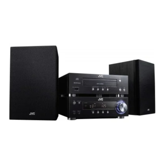
COMPACT COMPONENT SYSTEM
3 S ERVICE MANUAL
2010
MB725<Rev.001>
UX-TB30B, UX-TB30E, UX-TB30EN,
COPYRIGHT © 2010 Victor Company of Japan, Limited
Lead free solder used in the board (material : Sn-Ag-Cu, melting point : 219 Centigrade)
1
PRECAUTION. . . . . . . . . . . . . . . . . . . . . . . . . . . . . . . . . . . . . . . . . . . . . . . . . . . . . . . . . . . . . . . . . . . . . . . . . 1-3
2
SPECIFIC SERVICE INSTRUCTIONS . . . . . . . . . . . . . . . . . . . . . . . . . . . . . . . . . . . . . . . . . . . . . . . . . . . . . . 1-6
3
DISASSEMBLY . . . . . . . . . . . . . . . . . . . . . . . . . . . . . . . . . . . . . . . . . . . . . . . . . . . . . . . . . . . . . . . . . . . . . . . 1-6
4
ADJUSTMENT . . . . . . . . . . . . . . . . . . . . . . . . . . . . . . . . . . . . . . . . . . . . . . . . . . . . . . . . . . . . . . . . . . . . . . . 1-10
5
TROUBLESHOOTING . . . . . . . . . . . . . . . . . . . . . . . . . . . . . . . . . . . . . . . . . . . . . . . . . . . . . . . . . . . . . . . . . 1-10
UX-TB30EV
SP-UXTB30
TABLE OF CONTENTS
COPYRIGHT © 2010 Victor Company of Japan, Limited
XT-UXTB30
AX-UXTB30
SP-UXTB30
No.MB725<Rev.001>
2010/3
Advertisement
Table of Contents

Related Manuals for JVC UX-TB30B


Summary of Contents for JVC UX-TB30B
-
Page 1: Table Of Contents
SERVICE MANUAL COMPACT COMPONENT SYSTEM MB725<Rev.001> 2010 3 S ERVICE MANUAL UX-TB30B, UX-TB30E, UX-TB30EN, UX-TB30EV XT-UXTB30 SP-UXTB30 AX-UXTB30 SP-UXTB30 COPYRIGHT © 2010 Victor Company of Japan, Limited Lead free solder used in the board (material : Sn-Ag-Cu, melting point : 219 Centigrade) TABLE OF CONTENTS PRECAUTION. -
Page 2: No.mb725
SPECIFICATION Amplifier unit (AX-UXTB30) 20 W per channel, min. RMS, driven into 6 Ω at 1 kHz with no more than 10% total harmonic distortion. Output Power (IEC268-3) 6 Ω - 8 Ω Speakers/Impedance Player/tuner unit (XT-UXTB30) Tuner section FM tuning range 87.50 MHz - 108.00 MHz CD player section Measurement Condition... -
Page 3: Precaution
SECTION 1 PRECAUTION Safety Precautions (1) This design of this product contains special hardware and voltmeter. many circuits and components specially for safety purpos- Move the resistor connection to each exposed metal es. For continued protection, no changes should be made part, particularly any exposed metal part having a return to the original design unless authorized in writing by the path to the chassis, and measure the AC voltage across... -
Page 4: No.mb725
Preventing static electricity Electrostatic discharge (ESD), which occurs when static electricity stored in the body, fabric, etc. is discharged, can destroy the laser diode in the traverse unit (optical pickup). Take care to prevent this when performing repairs. 1.5.1 Grounding to prevent damage by static electricity Static electricity in the work area can destroy the optical pickup (laser diode) in devices such as laser products.)1 - Page 5 Important for laser products 1.CLASS 1 LASER PRODUCT 5.CAUTION : If safety switches malfunction, the laser is able to function. 2.CAUTION : (For U.S.A.) Visible and/or invisible class II laser radiation 6.CAUTION : Use of controls, adjustments or performance of when open.
-
Page 6: Specific Service Instructions
SECTION 2 SPECIFIC SERVICE INSTRUCTIONS This service manual does not describe SPECIFIC SERVICE INSTRUCTIONS. SECTION 3 DISASSEMBLY Amplifier unit (Used model is UX-TB30E) 3.1.2 Removing the Main board (See Fig.3, 4) (1) Disconnect the card wire from Display board connected to 3.1.1 Removing the Top cover (See Fig.1, 2) connector CN303... - Page 7 (6) Remove the three screws E attaching the Heat sink. (See (2) Disengage two hooks a engaged both side of the Front Fig.4) panel. (See Fig.7) hook Fig.7 3.1.5 Removing the Display board (See Fig.8) (1) Remove the five screws H attaching the Display board. (2) Disconnect the connector wire from Volume board con- nected to connector CN702...
- Page 8 CD unit (Used model is UX-TB30E) (3) Remove the two screws D attaching the Front panel. (See Fig.4) 3.2.1 Removing the Top cover (See Fig.1, 2) (1) Tear off the Rubber foots. (See Fig.1) (2) Remove the four screws A attaching the Top cover. (See Fig.1) Rubber foot Fig.1...
- Page 9 3.2.3 Removing the CD mechanism (See Fig.6, 7) 3.2.4 Removing the CD board (See Fig.8) (1) Disconnect the connector wire from Equalizer board con- (1) Disconnect the card wire from Equalizer board connected nected to connector CN2701 of the CD door switch board. to connector CN702 of the CD board.
-
Page 10: Adjustment
SECTION 4 ADJUSTMENT This service manual does not describe ADJUSTMENT. SECTION 5 TROUBLESHOOTING This service manual does not describe TROUBLESHOOTING. 1-10 (No.MB725<Rev.001>) - Page 12 Victor Company of Japan, Limited Home Entertainment Business Division Personal AV Operation 10-1,1chome,Ohwatari-machi,Maebashi-city,371-8543,Japan (No.MB725<Rev.001>) Printed in Japan...
-
Page 13: Parts List
PARTS LIST UX-TB30B, UX-TB30E, UX-TB30EN, UX-TB30EV MODEL MARK UX-TB30B UX-TB30E UX-TB30EN UX-TB30EV * All printed circuit boards and its assemblies are not available as service parts. - Contents - 3- 2 Exploded view of general assembly and parts list (Block No.M1) 3- 6 Speaker assembly and parts list (Block No.M2) - Page 14 Exploded view of general assembly and parts list Block No. CD unit section CD door switch board CD board Tuner board CD BOX section EQ board USB board Control board...
- Page 15 AMP unit section Rectifer board Main board board Display board Volume board The parts without symbol number are not service.
- Page 16 Local 5TB-300000-002 CONTROL FRONT CABINET 5TB-300000-001 DISPLAY FRONT CABINET 5TB-300000-000 DISPLAY LENS 5TB-300200-001 CONTROL LENS 5TB-307000-001 VOLUME KNOB 500-081000-000 JVC MARK (x2) 5TB-332000-000 VFD BRACKET 5TB-308000-000 POWER KNOB 5TB-302000-000 CONTROL KNOB 5TB-351000-000 FUNCTION KNOB 5TB-386000-001 UP BACK COVER 5TB-386000-002...
- Page 17 Symbol No. Part No. Part Name Description Local 238-130150-602 SCREW 3x15mm PB(x4) 880-TB8002-040 VOLTAGE HOLE PLATE FOR MAIN PCB 466-103069-050 VOLTAGE HOLE PLATE FOR POWER PC 360-055133-002 MOTOR RF-300CA-10510 466-235013-013 STRAP FOR MOTOR 152-402328-000 POWER TRANSF PT1101 230V 222-250150-120 FERRITE BEAD LV44603-003A...
- Page 18 The parts without symbol number are not service. Speaker Block No. [M][2][M][M] Symbol No. Part No. Part Name Description Local 500-081000-000 JVC MARK (x2) 5TB-340000-000 SPEAKER NET BRACKET L/R (x2) 5TB-341000-000 SPEAKER FRONT L/R (x2) 238-140100-631 SCREW 4x10 mm PWA(x12)
-
Page 19: Electrical Parts List
Electrical parts list Main board Symbol No. Part No. Part Name Description Local Block No. [0][1] C453 302-311015-550 C CAPACITOR 100pF/50V Symbol No. Part No. Part Name Description Local C454 302-311015-550 C CAPACITOR 100pF/50V C455 302-341045-550 C CAPACITOR 0.1uF/50V C456 302-341045-550... - Page 20 Symbol No. Part No. Part Name Description Local Symbol No. Part No. Part Name Description Local R445 301-321025-016 RESISTOR 1kΩ 1/16W C711 302-311015-550 C CAPACITOR 100pF/50V R446 301-321025-016 RESISTOR 1kΩ 1/16W C712 302-311015-550 C CAPACITOR 100pF/50V R449 301-322725-016 RESISTOR 2.7KΩ...
- Page 21 Symbol No. Part No. Part Name Description Local Symbol No. Part No. Part Name Description Local C988 302-306805-550 C CAPACITOR 68pF/50V R942 301-300005-016 RESISTOR 0Ω 1/16W C989 302-306805-550 C CAPACITOR 68pF/50V R944 301-100005-014 RESISTOR 0Ω 1/4W C990 302-341045-550 C CAPACITOR 0.1uF/50V R945...
- Page 22 Symbol No. Part No. Part Name Description Local Symbol No. Part No. Part Name Description Local Q703 307-008050-030 TRANSISTOR 8050C/D Q704 307-008550-020 TRANSISTOR L305 221-045030-014 FERRITE BEAD Q710 307-008550-020 TRANSISTOR L306 221-045030-014 FERRITE BEAD L307 221-045030-014 FERRITE BEAD D706 206-304001-000 RECTIFIER...
- Page 23 Rectifer board Symbol No. Part No. Part Name Description Local Block No. [0][5] C390 302-321025-550 C CAPACITOR 0.001uF/50V C391 302-321025-550 C CAPACITOR 0.001uF/50V Symbol No. Part No. Part Name Description Local C392 302-321025-550 C CAPACITOR 0.001uF/50V C393 302-321025-550 C CAPACITOR 0.001uF/50V C394...
- Page 24 Symbol No. Part No. Part Name Description Local Symbol No. Part No. Part Name Description Local R103 301-434735-016 RESISTOR 47kΩ R104 301-431035-016 RESISTOR 10kΩ C483 302-321025-550 C CAPACITOR 0.001uF/50V R105 301-431035-016 RESISTOR 10kΩ C601 004-061062-216 E CAPACITOR 10uF/16V R107 301-300005-016 RESISTOR...
- Page 25 Packing materials and accessories parts list Block No. No additional / supplemental order of WARRANTY CARDs are available.vv A1,A2 The parts without symbol number are not service. 3-13...
- Page 26 Packing and Accessories Block No. [M][3][M][M] Symbol No. Part No. Part Name Description Local 601-TB3000-010 INST BOOK 601-TB3000-020 INST BOOK GER/FRE/ITA/DUT 601-TB3000-030 INST BOOK SPA/DAN/FIN/SWE/POR 601-TB3000-040 INST BOOK RUS/HUN/CZE/POL ------------ WARRANTY CARD BT-54039-1 244-342810-350 SYSTEM CABLE RM-SUXTB30R REMOCON UNIT 237-241500-012 FM ANTENNA 669-TB3000-000...
- Page 27 SCHEMATIC DIAGRAMS COMPACT COMPONENT SYSTEM UX-TB30B, UX-TB30E, UX-TB30EN, UX-TB30EV DVD-ROM No.SML2009S2 XT-UXTB30 SP-UXTB30 AX-UXTB30 SP-UXTB30 Lead free solder used in the board (material : Sn-Ag-Cu, melting point : 219 Centigrade) Contents Block diagrams Standard schematic diagrams Printed circuit boards 2-13 to 16 No.MB725SCH<Rev.001>...
- Page 28 In regard with component parts appearing on the silk-screen printed side (parts side) of the PWB diagrams, the parts that are printed over with black such as the resistor ( ), diode ( ) and ICP ( ) or identified by the " " mark nearby are critical for safety.
-
Page 29: Block Diagram
BLOCK DIAGRAM FM ANT. UX-TB30 BLOCK DIAGRAM FM/RDS MODULE AUX IN VFD DRIVER ECO-CTL IC701 UPD16311 U701 CA6812 MCU+3V3 REMOTE SENSOR IC301 IC302 TDA8947J SC7314 POWER AMP MOTOR IC502 LB1641 OPEN/CLOSE SW PHONE IC303 TDA1308 DISC IC403 IC902 7812 25P20 IC1101 IC901 RECTIFIER... - Page 30 Standard schematic diagrams MAIN section C454 100P C323 R328 CN305 220uF 120K AGND PH-L PH-R MUTE CN302 R302 AUX-R AUX-AGND R301 IC302 AUX-L Q305 Q307 8050 8050 R393 C326 R332 C453 220uF 100P R340 120K JK301 DGND ANGD R392 R463 ANGD D301 R422...
- Page 31 DISPLAY section LED701 IR701 VFD701 R388 LED702 CN301 PROGRAM GROUP TRACK REPEAT 1 RANDOM STEREO L310 2.5T AUX-R JAZZ AUX-GND L311 2.5T JK302 POPS NEWS ROCK INFO R761 AUX-L L309 2.5T CLASSIC Q710 SLEEP R389 8550 C770 CN702 Q701 R776 104P 9014 R382...
- Page 32 EQUALIZER section To CD section 1 CN901 CN407 C610 C372 C369 R369 C374 C360 C600 R368 JK305 AGND AGND C480 100P AUX-L C481 100P AGND AUX-GND R364 C364 R363 AUX-R C363 MAIN-R R379 L503 MAIN-L R378 L504 R737 C353 272P MUTE C368 C373...
- Page 33 TUNER section CN101 TU-RST TU-SCL TU-SDA RDS-DAT TU+3V3 To This sheet To EQUALIZER section CN504 DGND TU-R AGND TU-L RDS-DAT R109 CF101 IC101 R101 C109 C110 C114 R117 JK101 LOUT FMIP TU-L RFGND ROUT TU-R C115 R119 TU_RST C102 104P R131 C101 AGND...
- Page 34 RECTIFIER section To MAIN section To MAIN section CN1104 CN1101 AC INPUT IC1101 LM1117(3V3) CN405 MCU3V3 CN1102 R1109 USB-5V T3.15AL 250V Q1102 R1110 9014 MCU-GND ECO-CTL Q1103 9015 R1102 R1111 R1112 RL1101 R1103 R1101 L1101 540uH C1107 103/500V PT1101 DGND NOTE) Warning Parts that are shaded are critical...
- Page 35 CONTROL section CN704 MCU-GND SW720 R762 OPEN/CLOSE To EQUALIZER section CN703 AD2-KEY SW716 R775 PLAY SW719 R765 PRESET+ SW718 R768 PRESET- SW713 R770 TU-UP SW717 R771 STOP SW712 R767 TU-DN...
- Page 36 VOLUME section VR401 C416 104P R470 LED403 R472 LED402 C417 104P R471 LED401 CN401 LED-GND C418 104P LED+5V VOL- VOL-GND VOL+...
- Page 37 USB section CN601 DGND L604 L601 SEBG160808U300MT L605 L603 SEBG160808U300MT USB+5V JK601 DGND DGND...
- Page 38 CD DOOR SWITCH section CN2701 CLOSE SW2701 OPEN 2-10...
- Page 39 CD section 1 R983 D906 VCC_3V3 VC25 TC701 C701 D701 C702 220UF 0.1uF 0.1uF 1N5819 T7902 VC25 4.7uF VCC_3V3 R701 100K C703 VCC_3V3 C740 0.1uF R999 C996 0.1uF R706 R708 R707 330R R751 KEY2 MAINPOWER R709 AMUTE R705 R710 Q906 8050 R711 P-TU...
- Page 40 CD section 2 To This sheet SEV_3V3 M33V M33V 3V3SD_IC C919 3V3SD_IC 0.1uF R947 100K C958 0.1uF D903 R984 C979 1N4148 4.7K 1N4148 CLOSE_DET RESETJ R916 To This sheet D905 M33V_PAD To This sheet R917 MUTE34 R918 R985 R987 470R VREF_16 CD+8V R927...
- Page 41 Printed circuit boards MAIN board ( Lead free solder used in the board (material : Sn-Ag-Cu, melting point : 219 Centigrade) ) (foward side) (reverse side) IC403 IC404 CN404 J319 R420 FAN+ FAN- Q409 R397 R396 C1110 Q410 C412 C456 J304 C450 C458...
- Page 42 DISPLAY board VOLUME board ( Lead free solder used in the board (material : Sn-Ag-Cu, melting point : 219 Centigrade) ) ( Lead free solder used in the board (material : Sn-Ag-Cu, melting point : 219 Centigrade) ) (foward side) (foward side) VFD701 R701...
- Page 43 EQUALIZER board TUNER board ( Lead free solder used in the board (material : Sn-Ag-Cu, melting point : 219 Centigrade) ) ( Lead free solder used in the board (material : Sn-Ag-Cu, melting point : 219 Centigrade) ) (foward side) (foward side) 248-TB3010-114 V:TA-B...
- Page 44 CD board CD DOOR SWITCH board ( Lead free solder used in the board (material : Sn-Ag-Cu, melting point : 219 Centigrade) ) ( Lead free solder used in the board (material : Sn-Ag-Cu, melting point : 219 Centigrade) ) (foward side) (reverse side) R989...
- Page 45 < M E M O >...
- Page 46 Victor Company of Japan, Limited Home Entertainment Business Division Personal AV Operation Printed in Japan (No.MB725SCH<Rev.001>)
Need help?
Do you have a question about the UX-TB30B and is the answer not in the manual?
Questions and answers