Yamaha DM2000 Service Manual
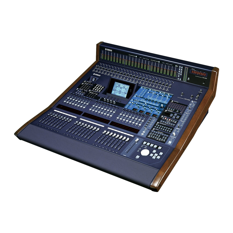
Digital product console/ peak meter bridge/ wooden side panels
Hide thumbs
Also See for DM2000:
- Owner's manual (402 pages) ,
- Installation manual (28 pages) ,
- Betriebssystem-installationshandbuch (13 pages)
Table of Contents
Advertisement
PEAK METER BRIDGE/WOODEN SIDE PANELS
This document is printed on chlorine free (ECF) paper with soy ink.
PA
011624
DIGITAL PRODUCTION CONSOLE/
/MB2000/SP2000
CONTENTS
INSPECTIONS
SERVICE CHECK PROGRAM
TEST PROGRAM
USING BULK DUMP
SAVING DM2000 DATA TO SMARTMEDIA
CHECKING THE BATTERY
INITIALIZING THE DM2000
MIDI DATA FORMAT
MIDI IMPLEMENTATION CHART
PARTS LIST
BLOCK DIAGRAM
OVERALL CONNECTOR CIRCUIT DIAGRAM
OVERALL CIRCUIT DIAGRAM
SERVICE MANUAL
................................................... 4
.......................................................... 19
.................................. 20
.................................. 69
....................................... 77
................................................... 142/150
......................... 181/182
1.302K-9377
DM2000
............... 36
............................ 41
....................... 58
................................ 59
. 159/170
....................... 183
............................ 184
................ 187
............... 187
............... 188
............................ 204
HAMAMATSU, JAPAN
Printed in Japan '02.03
1
Advertisement
Table of Contents

Related Manuals for Yamaha DM2000


Summary of Contents for Yamaha DM2000
- Page 1 INSPECTIONS ........... 142/150 SERVICE CHECK PROGRAM . 159/170 TEST PROGRAM ......181/182 USING BULK DUMP ....... 183 SAVING DM2000 DATA TO SMARTMEDIA ......184 CHECKING THE BATTERY ....187 INITIALIZING THE DM2000 ....187 MIDI DATA FORMAT ....188 MIDI IMPLEMENTATION CHART ......
-
Page 2: Specifications
IMPOR TANT NOTICE This manual has been provided for the use of authorized Yamaha Retailers and their service personnel. It has been assumed that basic service procedures inherent to the industry, and more specifically Yamaha Products, are already known and under- stood by the users, and have therefore not been restated. - Page 3 DM2000 LITHIUM BATTERY HANDLING This product uses a lithium battery for memory back-up. WARNING : Lithium batteries are dangerous because they can be exploded by improper handling. Observe the following pre- cautions when handling or replacing lithium batteries. Leave lithium battery replacement to qualified service personnel.
- Page 4 DM2000 SPECIFICATIONS DM2000 Number of scene memories Internal 44.1 kHz, 48 kHz, 88.2 kHz, 96 kHz Sampling Frequency Normal rate: 44.1 kHz–10% to 48 kHz+6% External Double rate: 88.2 kHz–10% to 96 kHz+6% Less than 2.3 ms CH INPUT to STEREO OUT (fs=48 kHz) Signal Delay Less than 1.2 ms CH INPUT to STEREO OUT (fs=96 kHz)
- Page 5 DM2000 Input patch — Phase Normal/reverse On/off Gate-type Key in: 12 ch Group (1–12, 13–24, 25–36, 37–48, 49–60, 61–72, 73–84, 85–96)/AUX1–12 On/off Key in: self /Stereo Link Comp-type Pre EQ/pre fader/post fader Attenuator –96.0 to +12.0 dB (0.1 dB step)
- Page 6 DM2000 Monitor select CONTROL ROOM, STEREO, AUX 11, AUX 12 STUDIO MONITOR OUT DA converter 24-bit linear, 128-times oversampling Level control Analog rotary potentiometer On/off Dither Word length 16, 20, 24-bit 2TR OUT DIGITAL 1–3 STEREO, BUS1–8, AUX 1–12, MATRIX 1L–4R, DIRECT OUT 1–96,...
-
Page 7: Dimensions
DM2000 On/off Comp-type Pre EQ/pre fader/post fader Attenuator –96.0 to +12.0 dB (0.1 dB step) 4-band PEQ On/off On/off — AUX1–12 Fader 100 mm motorized Delay 0–43400 samples Pre fader/post fader Matrix send Level (–∞,–96 dB to +10 dB) Pan: 127 positions (Left=1–63, Center, Right=1–63) - Page 8 DM2000 AC Cable Supplied Accessories CD-ROM (Studio Manager) Digital interface card (MY8, MY4 series) Options PEAK METER BRIDGE: MB2000 SIDE PANEL: SP2000 *1. Total harmonic distortion is measured with a 6 dB/octave filter @ 80 kHz. *2. Hum & Noise are measured with a 6 dB/octave filter @ 12.7 kHz; equivalent to a 20 kHz filter with infinite dB/octave attenuation.
- Page 9 DM2000 Comp Parameters Threshold –54 dB to 0 dB (0.1 dB step) x=1, 1.1, 1.3, 1.5, 1.7, 2, 2.5, 3, 3.5, 4, 5, 6, 8, 10, 20, ∞ (16 points) Ratio (x :1) Out gain 0 dB to +18 dB (0.1 dB step)
- Page 10 DM2000 Controls Analog Section +48 V switch ON/OFF PAD switch 0/26 dB INPUT 1–24 GAIN control –16 to –60 dB INSERT switch ON/OFF TALKBACK TALKBACK LEVEL control STUDIO MONITOR OUT STUDIO LEVEL control CONTROL ROOM MONITOR OUT CONTROL ROOM LEVEL control...
- Page 11 DM2000 DISPLAY button ROUTING 1, 2, 3, 4, 5, 6, 7, 8, STEREO, DIRECT, FOLLOW PAN buttons (w/LED) DISPLAY button PHASE/INSERT ø , INSERT ON buttons (w/LED) DISPLAY button ON button (w/LED) DELAY TIME control MIX/FB control (w/SW) DISPLAY, BANK button...
- Page 12 DM2000 DISPLAY, ALL CLEAR buttons 1, 2, 3, 4, 5, 6, 7, 8, 9, 10, 11, 12, 13, 14, 15, 16, 17, 18, 19, TRACK ARMING 20, 21, 22, 23, 24, MASTER, TRACK ARMING GROUP: A, B, C, D buttons (w/LED)
- Page 13 DM2000 Libraries Presets 52 (EFFECT 3–8: 44) Effect library (EFFECT 1–8) User memories Presets Compressor library User memories Presets Gate library User memories Presets EQ library User memories Presets Channel library User memories Presets GEQ library (GEQ 1–6) User memories...
-
Page 14: Analog Input Spec
DM2000 Analog Input Spec Input level For Use Actual Load Input PAD GAIN With Connector Max. Impedance Nominal Sensitivity Nominal before clip A: XLR-3-31 type (Bal- –60 –70 dB –60 dB –46 dB (0.245 mV) (0.775 mV) (3.88 mV) anced) 50–600 Ω... -
Page 15: Digital Input Spec
DM2000 Digital Input Spec Input Format Data length Level Connector AES/EBU 24-bit RS422 XLR-3-31 type (Balanced) 2TR IN DIGITAL AES/EBU 24-bit RS422 XLR-3-31 type (Balanced) 0.5 Vpp/75 Ω IEC-60958 24-bit PHONO D-SUB Half Pitch Connector 68P CASCADE IN — —... - Page 16 DM2000 I/O Slot Spec Each I/O SLOT accepts a digital interface card. Only SLOT #1 has a serial interface. Number of Card Name Function Accept Input Output available cards 8 OUT (depends on output MY8-AT ADAT 8 IN patch) 8 OUT (depends on output...
-
Page 17: Connector Pin Assignments
DM2000 Connector Pin Assignments CASCADE IN CASCADE OUT Signal Signal Signal Signal 35 GND 35 GND INPUT 1-2(+) 36 INPUT 1-2(–) OUTPUT 1-2(+) 36 OUTPUT 1-2(–) INPUT 3-4(+) 37 INPUT 3-4(–) OUTPUT 3-4(+) 37 OUTPUT 3-4(–) INPUT 5-6(+) 38 INPUT 5-6(–) OUTPUT 5-6(+) 38 OUTPUT 5-6(–) -
Page 18: Remote Port
DM2000 REMOTE Port Signal Signal RX+/GND RX–/RX– RTS/RX+ TX–/TX+ CTS/TX– TX+/GND N.C. *1. RS422 (for AD824)/SONY 9-pin protocol (P2). CONTROL Port Signal Signal GPO0 GPO1 GPO2 GPO3 GPO4 GPO5 GPO6 GPO7 GPI0 GPI1 N.C. N.C. SOLO SMODE MAS/SLV SPARE *1. For 02R SOLO control. - Page 19 371 mm 247 mm TALKBACK LEVEL 26dB 26dB 26dB 26dB 26dB 26dB 26dB 26dB 26dB 26dB 26dB 26dB 26dB 26dB 26dB 26dB 26dB 26dB 26dB 26dB 26dB 26dB 26dB 26dB GAIN GAIN GAIN GAIN GAIN GAIN GAIN GAIN GAIN GAIN GAIN GAIN GAIN...
- Page 20 Monitor, Phones & DISPLAY ACCESS (p. 23) Display Section (p. 24) AD Input Section (p. 21) SELECTED CHANNEL Section (p. 24) Talkback Section (p. 30) SmartMedia 26dB 26dB 26dB 26dB 26dB 26dB 26dB 26dB 26dB 26dB 26dB 26dB 26dB 26dB 26dB 26dB 26dB...
- Page 21 DM2000 AD Input Section q [+48V ON/OFF] switches 26dB w [PAD] switches e [GAIN] controls GAIN r [PEAK] indicators PEAK t [SIGNAL] indicators SIGNAL y [INSERT ON/OFF] switches INSERT Channel strips AUTO q Encoders SOLO w [AUTO] buttons e [SEL] buttons...
- Page 22 DM2000 SmartMedia CARD Slot 3.3V CARD MATRIX SELECT MATRIX SELECT q MATRIX SELECT [DISPLAY] button DISPLAY w [MATRIX 1]–[MATRIX 4] buttons MATRIX MATRIX MATRIX MATRIX AUX SELECT AUX SELECT DISPLAY q AUX SELECT [DISPLAY] button w [AUX 1]–[AUX 12] buttons...
- Page 23 DM2000 DISPLAY ACCESS q [DATA] button q w e r w [DIO] button DISPLAY ACCESS e [SETUP] button r [UTILITY] button DATA SETUP UTILITY t [REMOTE] button y [MIDI] button MIDI REMOTE METER VIEW u [METER] button i [VIEW] button...
- Page 24 DM2000 Display Section q Display w Contrast control e [F1]–[F4] buttons r Left Tab Scroll button t Right Tab Scroll button SELECTED CHANNEL Section SELECTED CHANNEL ROUTING PHASE / INSERT DELAY DISPLAY DISPLAY DISPLAY INSERT ON TIME AUX / MATRIX SEND...
- Page 25 DM2000 ROUTING ROUTING q ROUTING [DISPLAY] button DISPLAY w [FOLLOW PAN] button e [STEREO] button r [DIRECT] button t ROUTING [1]–[8] buttons FOLLOW PAN STEREO DIRECT PHASE/INSERT q PHASE/INSERT [DISPLAY] button PHASE / INSERT w Phase [ø] button DISPLAY INSERT ON...
- Page 26 DM2000 DYNAMICS DYNAMICS DISPLAY GATE / COMP GATE THRESHOLD RANGE ATTACK DECAY HOLD THRESHOLD RATIO ATTACK RELEASE GAIN COMP GATE ON COMP ON q DYNAMICS [DISPLAY] button w [GATE/COMP] button e [THRESHOLD], [RANGE], [ATTACK], [DECAY], [HOLD] ([THRESHOLD], [RATIO], [ATTACK], [RELEASE], [GAIN]) controls...
- Page 27 DM2000 EQUALIZER EQUALIZER LOW MID HIGH MID HIGH DISPLAY ATT. CHANNEL FREQUENCY FREQUENCY FREQUENCY FREQUENCY GAIN GAIN GAIN GAIN COPY EQ ON PASTE q EQUALIZER [DISPLAY] button w [EQ ON] button e [ATT] control r [FREQUENCY/Q] indicators t [FREQUENCY/Q] controls...
- Page 28 DM2000 STEREO STEREO AUTO q [AUTO] button w [SEL] button e [ON] button r Fader STEREO TRACK ARMING TRACK ARMING q TRACK ARMING [DISPLAY] button DISPLAY w TRACK ARMING [1]–[24] buttons e TRACK ARMING GROUP [A]–[D] buttons r [ALL CLEAR] button...
- Page 29 DM2000 AUTOMIX q AUTOMIX [DISPLAY] button w e r t y u i w [ENABLE] button AUTOMIX e [REC] button DISPLAY r [ABORT/UNDO] button ENABLE ABORT/ AUTO- RETURN RELATIVE TOUCH UNDO SENSE SUSPEND WRITE TOUCH LATCH READ TRIM t [AUTO-REC] button...
- Page 30 DM2000 Data Entry & Transport q [REW] button w [FF] button e [STOP] button STOP PLAY r [PLAY] button DISPLAY HISTORY t [REC] button BACK FORWARD y DISPLAY HISTORY [BACK]/ [FORWARD] buttons SHUTTLE u [SHUTTLE] button i [SCRUB] button SCRUB o [–DEC] &...
- Page 31 DM2000 MONITOR Section MONITOR STUDIO DISPLAY STUDIO MONITOR q MONITOR [DISPLAY] button DISPLAY w [CONTROL ROOM] button STEREO CONTROL STUDIO ROOM e [STEREO] button CONTROL STEREO r [AUX 11] button ROOM SOLO t [AUX 12] button SOLO CONTRAST CLEAR CONTROL ROOM...
- Page 32 AD Input Section (p. 33) Analog Master I/O Section (p. 33) OMNI OUT Section (p.33) Power Section (p. 34) Digital I/O & Control Section (p. 34) SLOT Section (p. 34)
- Page 33 DM2000 AD Input Section q [INPUT A & B (BAL)] connectors w [INSERT IN & OUT +4dB (BAL)] connectors Analog Master I/O Section q [STUDIO MONITOR OUT +4 dB (BAL)] jacks w [STEREO OUT +4 dB (BAL)] connectors e [SMALL CONTROL ROOM MONITOR OUT...
- Page 34 DM2000 Digital I/O & Control Section u i o q [KEYBOARD] connector w [SMPTE TIME CODE INPUT] connector e [MTC TIME CODE INPUT] connector r [USB TO HOST] port t [SERIAL TO HOST] port y [WORD CLOCK OUT 2] connector u [WORD CLOCK OUT 1] connector i [WORD CLOCK 75Ω...
- Page 35 DM2000 MB2000 Controls q Channel indicators w [INPUT METERING POSITION] button & indicators e [OUTPUT METERING POSITION] button & indicators r [PEAK HOLD] button t [LAYER] buttons y [TIMECODE] counter u Meters i [STEREO] meters o [CONTROL ROOM] button ! 0 [LAMP DIMMER] knob...
-
Page 36: Circuit Board Layout
DM2000 CIRCUIT BOARD LAYOUT DM2000 Bottom Assembly < > Top View Power Supply Unit < > Rear View < > Top View Power Supply Unit... - Page 37 DM2000 Inside the shield box Shield Box Shield Box Cover < > Top View Power Supply Unit...
- Page 38 DM2000 Rear Assembly U < > Top View 2TRI < > Rear View 2TRI < > Top View...
- Page 39 DM2000 Control Panel Assembly < > Bottom View PN2 (2/2) LCD Assembly PN2 (1/2) PN4 (1/2) PN4 (2/2) Display Tube B (1/2) Display Tube B (2/2) Display Tube A < > PN2 (2/2) Bottom View PN2 (1/2) LCD Assembly Display Tube B (1/2)
- Page 40 DM2000 LCD Assembly < > Bottom View < > Bottom View LCDCOM (INV) LCDCOM (CNT) MB2000 < > Rear View < > Front View...
-
Page 41: Disassembly Procedure
FD2, please initialize them. (See page 187.) Disassembling the DM2000 Removing the SP2000 (Time required: About 5 minutes) 1-1. If the SP2000 is attached to the DM2000, remove the twelve (12) screws marked [A], and then both sides must be removed. (Fig.1) DM2000 SP2000... - Page 42 DM2000 Rear Assembly U (Time required: About 15 minutes) 4-1. Remove the SP2000. (See procedure 1.) 4-2. Remove the MB2000. (See procedure 2.) 4-3. Fasten the control panel assembly. (See procedure 3.) 4-4. Remove the two (2) screws marked [60D] and the seven (7) screws marked [60E].
- Page 43 DM2000 Bottom Assembly CPU Circuit Board (Time required: About 15 minutes) 5-1. Remove the SP2000. (See procedure 1.) 5-2. Remove the MB2000. (See procedure 2.) 5-3. Fasten the control panel assembly. (See procedure 3.) 5-4. Remove the five (5) screws marked [335]. The CPU circuit board can then be removed.
- Page 44 DM2000 <OK> <NG> Photo.6 Photo.7 OPT Circuit Board (Time required: About 20 minutes) 10-1. Remove the SP2000. (See procedure 1.) 10-2. Remove the MB2000. (See procedure 2.) 10-3. Fasten the control panel assembly. (See procedure 3.) 10-4. Fasten the rear assembly U. (See procedure 4.) 10-5.
- Page 45 DM2000 DC Fan Motor (Time required: About 20 minutes) 13-1. Remove the SP2000. (See procedure 1.) 13-2. Remove the MB2000. (See procedure 2.) 13-3. Fasten the control panel assembly. (See procedure 3.) 13-4. Fasten the rear assembly U. (See procedure 4.) 13-5.
- Page 46 DM2000 14-7. AC Inlet Assembly: Remove the screw marked [205B] and the cord holder. The AC inlet assembly can then be removed from the shield box. (Fig.6) 14-8. SW Circuit Board: Remove the power switch knob, the three (3) screws marked [205C] and the two (2) screws marked [210A].
- Page 47 DM2000 <Top view> <Rear view> P.C.B.holder [240] Power switch escutcheon Rear panel L [380] [370] [380] [235] x 6 [370] [225] Power switch knob [355] [350A] [225]: Bonding Tapping Screw-B 3.0X8 MFZN2BL (VN413300) [235]: Bonding Tapping Screw-B 3.0X8 MFZN2BL (VN413300) [240]: Bind Head Tapping Screw-B 3.0X8 MFZN2BL (EP600190)
- Page 48 DM2000 ANI Circuit Board (Time required: About 20 minutes) 16-1. Remove the SP2000. (See procedure 1.) 16-2. Remove the MB2000. (See procedure 2.) 16-3. Fasten the control panel assembly. (See procedure 3.) 16-4. Remove the PC support. (See procedure 15.) 16-5.
- Page 49 DM2000 DA2 Circuit Board (Time required: About 25 minutes) 19-1. Remove the SP2000. (See procedure 1.) 19-2. Remove the MB2000. (See procedure 2.) 19-3. Fasten the control panel assembly. (See procedure 3.) 19-4. Remove the PC support. (See procedure 15.) 19-5.
- Page 50 DM2000 Control Panel Assembly When removing the circuit board, if it is hard to handle while the control panel assembly is fixed slantwise at the front stay, open it widely at 180° for the work. SUB Circuit Board (Time required: About 15 minutes) 20-1.
- Page 51 DM2000 PN4 Circuit Board (Time required: About 15 minutes) 25-1. Remove the SP2000. (See procedure 1.) 25-2. Remove the MB2000. (See procedure 2.) 25-3. Remove the knob wheel and the hexagonal nut from the control panel side. (Fig.9, Photo.8) 25-4. Fasten the control panel assembly. (See procedure 3.) 25-5.
- Page 52 DM2000 29-6. Display Tube B (2/2): Remove the four (4) screws marked [180C]. The display tube B (2/2) can then be removed. (Fig.11) LCD Assembly (Time required: About 5 minutes) 30-1. Remove the eight (8) screws marked [290B] from the control panel side. The LCD assembly can then be removed.
- Page 53 DM2000 [265] <Bottom view> [270B] A view (Back side) Smart media escutcheon Smart media angle bracket [200B] x 10 [230A] x 16 [230B] x 10 [200B]: Bind Head Tapping Screw-B 3.0X8 MFZN2BL (EP600190) [230]: Bind Head Tapping Screw-B 3.0X8 MFZN2BL (EP600190) [265]: Bind Head Tapping Screw-B 3.0X8 MFZN2BL (EP600190)
- Page 54 DM2000 [180D] <Bottom view> LCD bracket [120] Rear LCD case [120] [120] [125] <Bottom view> [120]: Bind Head Tapping Screw-B A4.0X8 MFZN2BL (VC688800) [125]: Bind Head Tapping Screw-B A3.0X6 MFZN2BL (VP157900) [180D]: Bind Head Tapping Screw-B A4.0X8 MFZN2BL (VC688800) Fig.12 LCD case assembly <Bottom view>...
- Page 55 DM2000 LCDCOM (CNT+INV) Circuit Board and LCD (Time required: About 15 minutes each) 31-1. Remove the LCD assembly. (See procedure 30.) 31-2. Remove the four (4) screws marked [180D]. The LCD bracket can then be removed. (Fig.12) 31-3. Remove the six (6) screws marked [120] and the five (5) screws marked [125].
- Page 56 DM2000 Cannon Connector (Time required: About 15 minutes) 35-1. Remove the rear panel. (See procedure 32.) 35-2. Remove the two (2) screws marked [110] from the rear side. The cannon connector can then be removed. (Fig.15) The opposite cannon connector can be removed in the same manner.
- Page 57 DM2000 [60G] x 9 [60H] x 9 <Rear view> Front panel [110] Back side <Front view> [150F] [110] Back side [90] x 6 Bushing Rear panel Cannon connector Cable holder DSUB cable [60]: Bind Head Tapping Screw-B 3.0X8 MFZN2BL (EP600190)
- Page 58 4 Secure the card using the attached thumbscrews. Do not leave them loose, as the card will not be grounded correctly, which may cause the DM2000 to malfunction. You can check which I/O Cards are installed on the Word...
-
Page 59: Lsi Pin Description
DM2000 LSI PIN DESCRIPTION M37640M8-101FP (XW147100) CPU ................... 59 32KM37640M8-138FP (X0157100) CPU ..................59 SH7709A FP-208C (XY065A00) CPU ................... 60 HD64F7044F28 (X2962A00) CPU ....................61 HD6437042AF28 (X2824A00) CPU ....................61 YSS910-S (XV988A00) DSP6 (Digital Signal Processor) ............62 YSS919-H (XZ693A00) DSP7 (Digital Signal Processor) ............63 SGH603064F-62F (XV973A00) Gate Array .................. - Page 60 DM2000 SH7709A FP-208C (XY065A00) CPU CPU: IC101 NAME FUNCTION NAME FUNCTION Clock mode CKE/PTK[5] CK enable/Port K Clock mode RAS3L/PTJ[0] DRAM row address strobe/Port J Vcc-RTC*1 Power supply for RTC (1.8 V) RAS2L/PTJ[1] DRAM row address strobe/Port J XTAL2 Crystal oscillator for RTC...
- Page 61 DM2000 HD64F7044F28 (X2962A00) CPU DM2000/SUB: IC101, 107 HD6437042AF28 (X2824A00) CPU MB2000/PN2: IC211 NAME FUNCTION NAME FUNCTION PE14 Port E PE15 Port E Data bus Ground Ground Data bus Power supply Address bus Data bus Ground XTAL Crystal oscillator Mode control...
- Page 62 DM2000 YSS910-S (XV988A00) DSP6 (Digital Signal Processor) DSP: IC401-408 NAME FUNCTION NAME FUNCTION Power supply (3.3V) Ground Ground DB13 System master clock input (60MHz or 30MHz) DB14 System master clock output (High or 30MHz) DB15 Power supply (5V) DB16 /SYNCI Sync.
- Page 63 DM2000 YSS919-H (XZ693A00) DSP7 (Digital Signal Processor) DSP: IC101-114 NAME FUNCTION NAME FUNCTION PLLEN PLL enable input (0: PLL unuse, 1: PLL use) SIO32 /TEST Test mode setting (0: TEST, 1: Normal) SIO33 AVss Analog ground SIO34 PLL filter SIO35...
- Page 64 DM2000 SGH603064F-62F (XV973A00) Gate Array SUB: IC119-122 NAME FUNCTION NAME FUNCTION Data bus Encoder input Ground Data bus Ground Ground Encoder input Data bus Ground Ground Data bus Ground Encoder input Not used Ground RA10 Encoder input RB10 RA11 RB11...
- Page 65 DM2000 YM6604C-S (XU240A00) ACIA (Asynchronous Communication Interface Adapter) DSP: IC703 NAME FUNCTION NAME FUNCTION RESETN Reset Not used Not used IRQ3N Interrupt request Chip select IRQ4N Address strobe Not used LDSN Data strobe IRQ5N Address bus IRQ6N Interrupt request Not used...
- Page 66 DM2000 MSM82C51A-2GS-KR1 (XV513A00) USART (Universal Synchronous Asynchronous receiver Transmitter) JK1: IC354 NAME FUNCTION NAME FUNCTION Data Bus TXRDY Character data Data Bus SYNDET/BD Character data Serial Data /CTS Input terminal for modem interface Ground TXEMPTY Character data Data Bus Character data...
- Page 67 DM2000 XCS40-3PQ240C (XZ334A00) FPGA (Field Programmable Gate Arrays) DSP: IC056 NAME FUNCTION NAME FUNCTION Ground Power supply +5V CPUCLK Primary global /PROGRAM Active low input /CSIN2 /CSATSC[3] Unrestricted user-programmable Input/Output pin /CSIN3 Unrestricted user-programmable Input/Output pin I/O/PGCK3 Primary global /CSATSC[4]...
- Page 68 DM2000 S1D13305F00B100 (XQ595A00) LCDC (LCD Controller) CPU: IC129 NAME FUNCTION NAME FUNCTION Data bus output for 4 bit dot VRAM address bus XECL S driver enable, chain clock XSCL Data bus shift clock Ground /VWR VRAM read/write X driver latch pulse...
-
Page 69: Ic Block Diagram
DM2000 IC BLOCK DIAGRAM DM2000 TC74VHC00F (XT229A00) TC74VHC02F (XT230A00) TC74VHC04F (EL) (XM332A00) CPU: IC133 JK1: IC353 CPU: IC132 DSP: IC058 ,704 DSP: IC702 Quad 2 Input NOR JK1: IC409, 410 MM74HC00SJX (XW105A00) DS: IC005 FD1: IC138 HD74LV04AFPEL (IS000400) FD2: IC127... - Page 70 DM2000 SN74LV138ANSR (IS013810) TC74VHC139F (EL) (XW324A00) TC74VHC153F (XV794A00) SUB: IC118 CPU: IC125 JK1: IC054, 056, 057 JK1: IC401 Dual 4 to 1 Data Selectors TC74HC138AFEL (XW762A00) Dual 2 to 4 Demultiplexer SUB: IC125, 129 TC74VHC138F (XT015A00) JK1: IC402 JK2: IC905...
- Page 71 DM2000 TC74VHC244F (XT800A00) MM74HC273SJX (XY198A00) HD74LV245AFPEL (IS024500) CPU: IC118 FD1: IC104-109 SUB: IC102, 106 DSP: IC904, 905 FD2: IC104-107 TC74HC245AF (XS720A00) JK1: IC455, 458 TC74VHC273F (EL) (XY254A00) JK2: IC903, 904 AD: IC001, 002 DS: IC003 JK1: IC405-408 DA1: IC901, 902...
- Page 72 DM2000 HD74LV4053AFPEL (IS405300) TC74LVX4245FS (XU229A00) SN75121NSR (XU816A00) DSP: IC060, 062 CPU: IC127 JK1: IC151 JK2: IC752, 753 DSP: IC010, 011, 021, 022, 028-031 Dual Line Driver Triple 2-Channel Dual Supply Octal Bus Transceiver Multiplexer/Demultiplexer VCCA VCCB VCCB Switches IN/OUT +DC Voltage Supply - do.
- Page 73 DM2000 AM26LS31CNSR (XU996A00) TC7S04F (XM182A00) TC7SH04FU (XS775A00) JK2: IC501, 601-604 AD: IC003 CPU: IC122 DA1: IC900 DSP: IC012, 066 Quad Line Driver DA2: IC911 Inverter Gate Inverter Gate ENABLE G IN A ENABLE G OUT Y INPUT ENABLES OUTPUTS TC7W04FU (XP004A00)
-
Page 74: Real Time Clock
DM2000 CY2305 (XY937A00) CPU: IC114 Clock Buffer Block Diagram CLKOUT Pin No. Signal Function CLKA1 Input reference frequency, 5V-tolerant input CLK OUT CLKA2 CLK2 Buffered clock output CLK2 CLK4 CLK1 Buffered clock output CLKA3 Ground CLK1 CLKA4 CLK3 Buffered clock output 3.3V supply... - Page 75 DM2000 TLC2932IPWR (XV064A00) DSP: IC061, 063 LOGIC V PFD INHIBIT VCO INHBIT VCO V VCO OUT SELECT LOGIC V VCO V DETECTOR CHARGE PUMP SELECT BIAS VCO OUT COIN VCO GND VCO INHBIT PFD OUT PFD INHIBIT LOGIC GND LOGIC GND...
- Page 76 DM2000 MB2000 TC74HC238AF (XT163A00) PN2: IC214 3 to 8 Line Decoder Select Inputs Enable Data Inputs Output SN74HC245NSR (XD838A00) SN75C1168N (XU463A00) TD62M8600F (XV014A00) PN2: IC213 DC: IC303 PN1: IC102, 106, 110 PN2: IC201, 205 Line Driver/Receiver TC74HC245AF (XS720A00) Source Driver...
-
Page 77: Circuit Boards
DM2000 CIRCUIT BOARDS DM2000 2TRCOM (2TRI) Circuit Board (XZ035B0) ........78 2TRCOM (PHN) Circuit Board (XZ035B0) ........79 AD Circuit Board (XZ020B0) ............ 80/82 ANI Circuit Board (XZ032B0)............84 BRG Circuit Board (XZ031C0) ..........86/88 CPU Circuit Board (X0383B0) ..........90/91 CRCOM (LRG) Circuit Board (XZ033A0) ........ - Page 78 DM2000 2TRCOM (2TRI) Circuit Board 2TR IN ANALOG 1 2TR IN ANALOG 2 to DA2-CN151 Component side Pattern side 3NA-V628810-1...
- Page 79 DM2000 2TRCOM (PHN) Circuit Board PHONES LEVEL TALKBACK LEVEL PHONES OUT CN202: to TALKBACK MIC to DA2-CN701 Component side 3NA-V628810-1 Pattern side...
- Page 80 DM2000 AD Circuit Board to DSP-CN952, CN954 to DSP-CN951, CN953 3NA-V628540-2...
- Page 81 DM2000 CN101: to ANI#1,#13-CN100 CN102: to ANI#2,#14-CN100 CN201: to ANI#3,#15-CN100 CN202: to ANI#4,#16-CN100 CN301: to ANI#5,#17-CN100 CN302: to ANI#6,#18-CN100 CN401: to ANI#7,#19-CN100 CN402: to ANI#8,#20-CN100 CN501: to ANI#9,#21-CN100 CN502: to ANI#10,#22-CN100 CN601: to ANI#11,#23-CN100 CN602: to ANI#12,#24-CN100 to BRG-CN007, CN008...
- Page 82 DM2000 AD Circuit Board 3NA-V628540-2...
- Page 83 DM2000 Pattern side 3NA-V628540-2...
- Page 84 DM2000 ANI Circuit Board GAIN INSERT ON/OFF PAD 26dB +48V SIGNAL PEAK ON/OFF INPUT INSERT INSERT to AD #1, #2-CN101, CN102, CN201, CN202, CN301, CN302, CN401, CN402, CN501, CN502, CN601, CN602 Component side Pattern side 3NA-V628760-2...
- Page 85 DM2000 LCDCOM (INV) Circuit Board to LCD backlight to BRG-CN018 to CPU-CN106 to LCD Component side LCDCOM (CNT) Circuit Board CONTRAST Component side 3NA-V824910-2...
- Page 86 DM2000 BRG Circuit Board to Power Supply Unit to Power Supply Unit -CN102 to FAN to TEMP -CN103 to JK2 -CN906 to JK1 -CN907 to OPT -CN908 to OPT -CN907 to DSP-CN961 CN007: to AD #1-CN001 CN008: to AD #2-CN001...
- Page 87 DM2000 to Power Supply Unit to Power Supply Unit -CN104 -CN101 CN019: to PN1 -CN102 CN020: to PN2 (1/2) -CN302 CN021: to PN3 -CN502 to FD2 -CN102 to FD1 -CN102 to SUB -CN104 to LCDCOM to FL Module to DSP-CN962...
- Page 88 DM2000 BRG Circuit Board 3NA-V628730-2...
- Page 89 DM2000 Pattern side 3NA-V628730-2...
- Page 90 DM2000 CPU Circuit Board to SUB-CN102 to DS-CN001 to DS-CN002 to LCDCOM (INV)-CN903 not used (for check) not installed not installed not used (for check) to DSP-CN105 to DSP-CN104 Component side Lithium Battery Battery VN103500 VN103600(Battery holder for VN103500) Notice for back-up battery removal...
- Page 91 DM2000 CPU Circuit Board Pattern side 3NA-V776550-3...
- Page 92 DM2000 CRCOM (LRG) Circuit Board CONTROL ROOM MONITOR OUT LARGE to DA2-CN101 Component side Pattern side 3NA-V628790-1...
- Page 93 DM2000 CRCOM (SML) Circuit Board SMALL TRIM CONTROL ROOM MONITOR OUT SMALL to DA2-CN201 Component side 3NA-V628790-1 Pattern side...
- Page 94 DM2000 DA1 Circuit Board to BRG -CN009 OMNI OUT to DSP -CN955 Component side 3NA-V628550-1...
- Page 95 DM2000 DA1 Circuit Board Pattern side 3NA-V628550-1...
- Page 96 DM2000 DA2 Circuit Board to 2TRI-CN101 to LRG-CN001 to SML-CN002 to ST-CN001 to STD-CN002 to PHN-CN201 CN100: to PN3-CN505 to DSP-CN957 to DSP-CN956 to BRG-CN010 Component side 3NA-V628560-1...
- Page 97 DM2000 DA2 Circuit Board Pattern side 3NA-V628560-1...
- Page 98 DM2000 DSP Circuit Board CN801: to OPT-CN801 CN802: to OPT-CN802 CN804: to OPT-CN804 CN805: to OPT-CN805 CN951: to AD #1 -CN003 CN952: to AD #1 -CN002 to CPU-CN105 to CPU-CN104 3NA-V628520-2...
- Page 99 DM2000 CN803: to OPT-CN803 CN806: to OPT-CN806 to BRG -CN012 to AD #2 -CN003 CN954: to AD #2 -CN002 to OPT -CN807 CN955: to DA1 -CN901 CN956: to DA2 -CN901 to JK1 -CN901 CN902: to JK1 -CN902 CN957: to DA2...
- Page 100 DM2000 DSP Circuit Board 3NA-V628520-3...