
Related Manuals for LEYBOLD TURBOVAC 50


Summary of Contents for LEYBOLD TURBOVAC 50
-
Page 1: Operating Instructions
LEYBOLD VACUUM Service Vacuum Solutions Application Support GA05118_1302 TURBOVAC Turbomolecular pumps with grease-lubricated bearings Operating instructions... -
Page 2: Table Of Contents
Thick deposits re- 4.2 Service by LEYBOLD ..... 17 duce the play between moving parts to the point that the pump could seize. -
Page 3: Standard Equipment
Description 1.1 Standard equipment Both the purge gas port and the airing port are blanked off for shipping. is shipped in a sealed PE bag which TURBOVAC In addition the pivoted threaded fittings used to make the also contains a desiccant. coolant connection are included as standard equipment for the TURBOVAC 151, 361 and 600;... -
Page 4: Technical Data
Description 1.3 Technical data TURBOVAC 50 D2 High-vacuum port nom.diam. 40 KF 40 CF 63 ISO-K 63 CF 63 ISO-K Pumping speed for N l/sec Ultimate pressure mbar 8·10 < 10 8·10 < 10 < 10 Forevacuum pressure, max. N mbar Recommended fore- Diaphragm... - Page 5 Description TURBOVAC 600 C 600 C 1000 C 1000 C 1000 C High-vacuum port nom. diam. 160 ISO-K 6“ ANSI 160 ISO-K 6“ ANSI 250 ISO-K 160 CF 160 CF 200 CF Pumping speed for N l·s 1100 1150 Ultimate pressure mbar <...
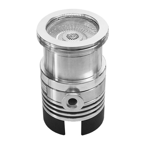
- Page 6 Description TURBOVAC 50 D2 TURBOVAC 151 C; TURBOVAC 361 C is similar TURBOVAC 50 Fig. 1 GA05118_1302 - 01/2004...
- Page 7 Description TURBOVAC 600 C TURBOVAC 1000 C A High-vacuum connector flange B Forevacuum connector flange C Airing flange D Purge gas flange E Connection for water cooling F Electrical connection Fig. 2 GA05118_1302 - 01/2004...
-
Page 8: Connections
Connections Operating environment and cooling TURBOVAC No additional cooling required if all Air or water cooling required Water cooling required if any one of these these conditions are satisfied conditions prevails Ambient temperature 30 to 40 °C Ambient temperature 40 - 45 °C 50 D2 Ambient temperature <... -
Page 9: Operating Environment
Connection max. 100 mm (4 inch) max. 100 mm (4 inch) max. 100 mm Incorrect (4 inch) Fig. 4 Permanent flanging of the TURBOVAC to the vacuum chamber 2.1 Operating environment 2.2 Connecting the pump to the vacuum chamber When using the inside a magnetic field, the TURBOVAC magnetic induction at the pump housing surface may not... - Page 10 The O-ring should be flat and even; it must not be You will find the order numbers for the (clamping) bolts twisted. Then add the outer ring. in the Leybold Catalog. A collar flange with retaining ring and suitable sealing The clamping bolts are not included as standard equip- washer can also be used to connect the TURBOVAC.
- Page 11 Connection Legend for Fig. 6 Turbomolecular pump Forevacuum test point Forevacuum pump Anti-vibration bellows Adsorption trap Forevacuum valve Airing valve High-vacuum valve Purge gas connection 10 Valve in the roughing pump line 11 Electronic frequency converter — — — — Roughing pump line; recommended to achieve the shortest possible cycling times —...
-
Page 12: Making The Forevacuum Connection
Connection 2.3 Making the forevacuum Water cooling When attaching the water cooling unit to the TURBOVAC connection 50 and 50 D, remove the pump foot and then bolt the cooling unit to the bottom of the pump. The mounting A suitable forevacuum pump is to be connected to the bolts are provided with the water cooling unit. -
Page 13: Connecting The Turbotronik
Route the conductors and cables so as to protect them from damage. Please contact Leybold for assistance in making the decision as to which media can be pumped with or with- The connections are of the IP 40 safety classification. -
Page 14: Operation
Operation TURBOVAC mbar TURBOVAC 151 to 1000 = Pumping speed at the forevacuum pump (m V = Chamber volume (m Fig. 8 Determining the starting pressure for a TURBOVAC when evacuating larger volumes 3 Operation 3.2 Bakeout 3.1 Switching on If pressures in the range of 10 mbar are to be devel- oped within a short period of time, the vacuum chamber... -
Page 15: Switching Off
Operation mbar TURBOVAC 50 TURBOVAC 151, 361 TURBOVAC 600, 1000 Time Fig. 9 Curves showing the pressure rise 3.4 Switching off 3.5 Venting Switch off the at the As to suitable gases, see Chapter 2.5. TURBOVAC TURBOTRONIK Venting Methods Refer to the... -
Page 16: Removing The Pump From The System
Protect in particular the flanges, the coo- lant connection nipples and the cable grommets. If you return a pump to Leybold, be absolutely sure to observe the instructions given in Section 4.2. GA05118_1302 - 01/2004... -
Page 17: Maintenance
45,000 to 100,000 ope- purpose; we will forward that form on request. rating hours. This can only be done by Leybold Service. For this ask for a quotation. A copy of the form is printed at the end of the operating instructions: “Declaration of contamination for vacuum... -
Page 18: Troubleshooting
Minor grime collection at the pump. Bake out the pump; see Section 4.1. The pump is oily. Have the pump cleaned (only by the Leybold Service Department). Forevacuum pump with insufficient pumping speed Check ultimate pressure of the forevacuum pump or or ultimate pressure which is too high. -
Page 19: Ec Manufacturer's Declaration
855 35/36/38/39, 894 89 connector lines, flange heaters or fans, and when power- As from serial No. A 95 ..ing the pump with the specified Leybold frequency con- verters, the protection level prescribed in the EMC Guidelines will be attained... - Page 20 Notes GA05118_1302 - 01/2004...
- Page 21 Declaration of Contamination of Vacuum Equipment and Components The repair and/or service of vacuum equipment and components will only be carried out if a correctly completed declaration has been submitted. Non-completion will result in delay. The manufacturer could refuse to accept any equipment without a declara- tion.
- Page 22 EUROPE AMERICAS ASIA Germany: Italy: USA: P.R. China: Japan: LEYBOLD VAKUUM GmbH LEYBOLD VACUUM LEYBOLD VACUUM USA INC. LEYBOLD VACUUM Sales: Bonner Straße 498 (Bayent- ITALIA S.p.A. 5700 Mellon Road (Tianjin) LEYBOLD VACUUM hal) 8, Via Trasimeno Export, PA 15632 International Trade Co., Ltd.
Need help?
Do you have a question about the TURBOVAC 50 and is the answer not in the manual?
Questions and answers