
Related Manuals for LEYBOLD Turbovac TW 300


Summary of Contents for LEYBOLD Turbovac TW 300
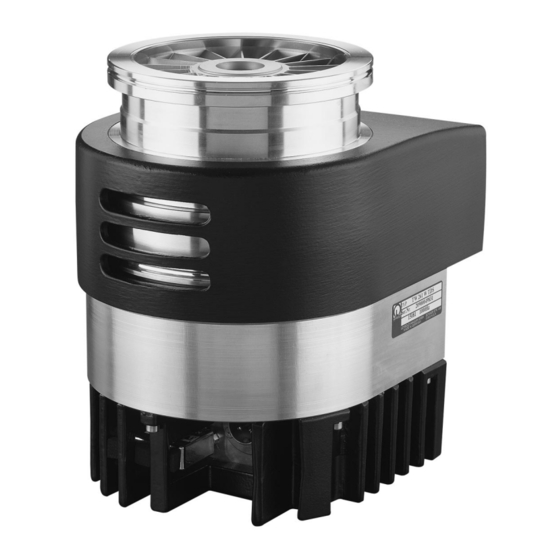
- Page 1 LEYBOLD VACUUM Vacuum Solutions Application Support Service GA05142_0902 TURBOVAC TW 300 TW 300 H Wide-Range Turbomolecular Pump with Integrated or External Frequency Converter Operating Instructions...
-
Page 2: Table Of Contents
Cleaning ......46 Service by LEYBOLD ....46 Troubleshooting . -
Page 3: Safety Information
Safety Information Safety information Failure to observe the following precautions could Electrical hazards result in serious personal injury: Warning Warning Mains voltage may be present at the power The turbomolecular pump must only be failure airing valve, the purge gas valve or operated in the proper condition and under the venting valve. - Page 4 If foreign objects could pass from the vacu- Pumps with integrated frequency converter um chamber into the pump, install a wire need to be shipped to the Leybold Service mesh splinter guard. Foreign objects which with the frequency converter. enter the pump through the intake would cause serious damage to the rotor.
-
Page 5: Description
Description 1 Description Use and media compatibility The TURBOVAC TW 300 and TW 300 H are turbomole- cular pumps with integrated or external frequency con- verter. They are designed to evacuate vacuum cham- bers down to pressure levels in the high vacuum range. -
Page 6: Design
The cant to absorb moisture.The maximum useful life of the design of a TURBOVAC TW 300 is depicted in Fig. 1. desiccant is one year. The rotor consists of a turbomolecular pump stage and a The flanges for forevacuum, venting, and purge gas are Holweck stage. -
Page 7: Ordering Data
800170V2103 DN 160 ISO-K, water cooling, with TURBO.DRIVE 300 with RS 485, without splinter guard 800170V2108 TURBOVAC TW 300 H DN 100 ISO-K, air cooling, with TURBO.DRIVE 300 with RS 485, without splinter guard 800170V2107 DN 100 CF, air cooling, with TURBO.DRIVE 300... -
Page 8: Frequency Converter And Accessories For The Frequency Converter
Description 1.3.2 Frequency converter and accessories for the frequency converter Frequency converter Frequency converter Basic unit with RS 232/422 interface 800072V0001 with RS 485 interface 800072V0003 Connecting cable pump - frequency converter 1.0 m long 152 47 2.5 m long 864 49 3.0 m long 864 40... - Page 9 Description Power supply and control unit TURBO.CONTROL 300 800100V0001 START START • supplies the TURBO.DRIVE 300 with 24 V DC NORMAL • plug & play cables STOP • desktop unit or rack mountable POWER • with power switch • with start/stop switch for the turbomolecular pump ERROR •...
- Page 10 Description Accessories for serial interfaces Display PDA* (display unit for parameters, requires the software "Turbo.Drive Panel”) upon request data cable and adaptor Required "Turbo.Drive Panel" software for the display PDA with operating system OS 4.0 to 4.x, 3.5" floppy 800110V0104 PC software "Turbo.Drive Server"...
-
Page 11: Accessories For The Pump
Description 1.3.3 Accessories for the pump Splinter guard coarse, DN 100 ISO-K 800132V0101 Splinter guard fine, DN 100 ISO-K 800132V0102 Purge gas and venting valve 24 V DC 800120V0001 Venting valve 24 V DC 800120V0011 Power failure airing valve 24 V DC 800120V0021 Water cooling unit with G 1/8”... -
Page 12: Technical Data
Description 1.4 Technical data 1.4.1 TURBOVAC TW 300 TW 300 TW 300 H TW 300 H ————————————————————————————————————————————————————————— High-vacuum connection DN 100 ISO-K DN 100 CF DN 100 ISO-K DN 100 CF DN 160 ISO-K Pumping speed at 10 mbar 240/240 l·s 240/240 l·s 240/240 l·s 240/240 l·s... - Page 13 WARNING 12,5 Ser.Nr. XXXXXXXXXXX XXX XX XXX Hz Hot Surface LEYBOLD VAKUUM GMBH BONNER STR.498 MADE IN GERMANY 50968 K@RLN Fig. 2 Dimensional drawing for the TW 300 / TW 300 H with mounted frequency converter; dimensions in mm 70,4...
-
Page 14: Power Supply Sitop 24 V / 10 A
Description 1.4.2 TURBO.DRIVE 300 1.4.3 Power supply SITOP 24 V / 10 A Supply voltage 24 V (21 ... 29 V) AC input voltage 120/230 V, 50/60 Hz Residual ripple < 3 % Tolerance 93 - 132 V Output 187 - 264 V Voltage 0 - 24 V 3~ Recommended circuit breaker... -
Page 15: Turbo.drive 300
Description 73,2 DRIVE (X3) 24 V (X4) 29,3 22,2 HEAT SINK 79,7 40,7 TURBO.DRIVE 300 16,85 SERVICE (X5) REMOTE (X1) HEAT SINK 18,1 63,8 Fig. 4 Dimensional drawing for the frequency converter and the OEM power supply unit, dimensions in mm GA05142_0902 - 12/2003... -
Page 16: Connections
Connections 2 Connections 2.2 Attach the pump to the Caution The pumps are not suitable for pumping vacuum chamber aggressive or corrosive media or those which contain dust. Warning The high-vacuum flange must be solidly Install a micropore filter when pumping mounted to the vacuum chamber. - Page 17 Connections Splinter guard (accessory) High-vacuum flange Purge gas and venting connection Forevacuum PURGE connection VENT TURBO.DRIVE 300 SERVICE (X5) REMOTE (X1) HEAT SINK Fig. 5 Connection elements GA05142_0902 - 12/2003...
- Page 18 The order numbers for the flange components are given Insert the splinter guard so that the surface curvature is in the Leybold Catalog. at the top and apply some pressure lightly at the rim so that the splinter guard engages. The splinter guard must not touch the rotor.
-
Page 19: Forevacuum Connection
Connections Centering ring with O-ring KF flange from the forevacuum line Clamping yoke Screws Fig. 8 Connecting the forevacuum line 2.3 Forevacuum connection A separate safety valve is provided for oil-sealed foreva- cuum pumps without an anti-suckback valve. The safety valve prevents oil flowing back from the forevacuum As forevacuum pump we recommend using the dry com- pump into the turbomolecular pump when the system is... -
Page 20: Connect The Cooling
Connections 2.4 Connect the cooling Air cooling The air cooling facility has two powerful fans capable of Cooling of the TW 300 depends on the required pumping passing a large quantity of air past the pumps’ casing, power and the ambient temperature; see Fig. 9. When see Fig. - Page 21 Connections Screws (4x) Plug Connector pump TW 300 with air cooler mounted Relief for cable Connector air cooler Fig. 9 Mounting the air cooling GA05142_0902 - 12/2003...
- Page 22 Connections °C Cooling water temperature Fig. 10 Cooling water requirements Mounting the water cooling (optional) Connecting the cooling water Screw on the cooling water lines. Unscrew 2 screws and bend the cooling coil cautiously a little bit open. Mount it to the pump and fix the 2 screws. The cooling water may be connected radially or axially to the connecting piece of the cooling coil;...
- Page 23 Connections Ø 160 Fig. 11 Optional air cooling optional Connecting piece G 1/8" of the cooling coil G 1/8" Part No. 800170V2106 with hose nipples Ø 10 mm Fig. 12 Optional water cooling GA05142_0902 - 12/2003...
-
Page 24: Connect The Purge Gas And Venting Valve
When pumping abrasive media, connect a purge gas and venting valve, so as to protect the bearings against light contamination. Please contact Leybold for assistance in making the decision as to which media can be pumped with or with- out purge gas. - Page 25 Connections 1 Turbomolecular pump 2 Forevacuum gauge port 3 Forevacuum pump 4 Resonance damper 5 Adsorption trap 6 Forevacuum valve 7 Vent valve 8 High-vacuum valve 9 Valve in the roughing pump line 10 Electronic frequency converter — — — — Roughing line;...
-
Page 26: Electrical Connection
The TURBO.DRIVE 300 frequency converter needed to Only required in the case of a separate frequency con- operate the TURBOVAC TW 300 / TW 300 H has either verter. been integrated in the pump or is a separate unit. For connection examples see Fig. -
Page 27: Connecting The Power Supply
Fig. 17 Connect the extension cable Model Hirose HS16P-3 2.6.2 Connecting the power supply The frequency converter is equipped with an internal 8 AT (slow blow) fuse. It can only be replaced by Leybold Warning staff. The frequency converter must only be Connect the power supply to the mains. -
Page 28: Mounting The Frequency Converter
M4 sliding nuts. The bottom side of the fre- quency converter must be cooled sufficiently. Ensure an adequate supply and discharge of cooling air. For special requirements please contact Leybold. Warning During operation the frequency converter may attain temperatures up to 75 °C. We recommend that the unit be installed so that it can not be touched inadvertently. - Page 29 Connections REMOTE 93 - 132 / DRIVE (X3) DC 24 V 187 - 264 (X4) V AC, 50/60 Hz HEAT SINK 24 V DC Recommended for pumps and frequency converters not connected to ground 120 V Optional jumper for operating voltage range 93 - 132 V + 24 V DC 0 V DC...
- Page 30 Connections DRIVE (X3) DC 24 V (X4) T 5 A ~ 250 V 100 - 240 V AC 100 - 240 V AC 50/60 Hz T 5 A ~ 250 V TURBO.POWER 300 HEAT SINK In the case of an integrated 24 V DC Power cable TURBO.DRIVE 300 the connecting cable is omitted.
-
Page 31: Relay Status
Connections 2.6.4 Relay status Input data / status Output data Operating mode Start/ Pump Normal Error is Motor Relay Relay Other modes are not possible; they indicate stop rotating frequency present drive ERROR STATUS ERROR a failure affecting the TURBO.DRIVE 300. NORMAL ≥... -
Page 32: Installing The Frequency Converter (Optional)
Connections Adapter cable with mounting panel Bolts M4x25 (2 pieces) Frequency converter Heat sink Bolts M4x12 (4 pieces) Bolts M4x5 (4 pieces) Fig. 23 Optional installation of the frequency converter to the pump 2.6.5 Installing the frequency converter (Optional) The frequency converter may be retrofitted to the pump. The part numbers for the necessary installation compo- nents are provided on Chapter 1.3.2. -
Page 33: Interface Description
Connections 2.7 Interface description Profibus DP The frequency converter may be equipped with either of the following interfaces (optional): The Profibus DP used has been defined in the standards • RS 232/RS 422(485) EN 50170, DIN 19245-1, -3, VDI/VDE 3689. •... -
Page 34: Rs 232/Rs 422(485) Interface (Service X5)
Connections + 5 V 390 Ω TxD/RxD — 150 Ω 120 Ω RS 422 Master TxD/RxD + 390 Ω TxD/ TxD/ RxD + RxD — Pin 7 Pin 8 GND, Pin 5 TURBO.DRIVE 300 TURBO.DRIVE 700 RS 422 (Socket) RS 422 (Buchse) SERVICE, X5 SERVICE, X5 Fig. -
Page 35: Rs 485 Interface
Connections + 5 V 390 Ω For longer cable runs: Links for activation of the bus terminator Bus terminator for longer cable runs 150 Ω TxD/RxD – 120 Ω TxD/RxD + 390 Ω TURBO.DRIVE X5 (7) X5 (8) X5 (7) X5 (8) TURBO. -
Page 36: Parameter List
Connections 2.7.3 Parameter list Designation Range Unit Default Format Description Dummy parameter No function Type of frequency 132 / 134 TURBO.DRIVE 300 = 132 converter Software version xx.yy.zz 1.12.02 xx.yy: version, zz: correction index Actual rotor frequency 0...1300 The max. frequency depends on the pump type. - Page 37 Connections Designation Range Unit Default Format Description Selection of the relay 0 ... 4 The normal operation and error relays functions can be set to special functions if required. P29 = 0 means: the normal operation relay is active when the normal operation frequency is exceeded (P3 ≥...
- Page 38 Connections Designation Range Unit Default Format Description Bearing temperature Max. permissible bearing temperature; shutdown level 30...150 °C P125 > P132 causes the pump to be switched off Motor temperature Max. permissible motor temperature; shutdown level 30...150 °C P7 > P133 causes the pump to be switched off Current reduction factor 30...100...
-
Page 39: Warning Codes For Parameter 227
Connections Designation Range Unit Default Format Description Converter date of 01.01.00 ... manufacture 31.12.99 Warnings bits 1 0 ... 65535 Active warnings described bit per bit; for the meaning see Section 4.5 Pump status word Meaning of the bits: Bit 0 = 1 Normal operation Bit 1 = 1 Ready for switch on Bit 2 = 1 Speed is increasing Bit 3 = 1 Speed is dropping... -
Page 40: Error Codes For Parameter P171
Connections 2.7.5 Error codes for parameter P171 Code Type of error Condition / Description of the error Pump switched off No error – Overspeed error Nominal speed of the pump (P 18) has been exceeded by over 10% Pass through time error Max. - Page 41 Connections Code Type of error Condition / Description of the error Pump switched off Parameter value error Parameter value internally not valid; data error Data plausibility error Internal data error (open loop) Motor blocked error Rotor blocked PLL error PLL synchronisation error Shut down Emergency off Overvoltage error...
-
Page 42: Operation
For the power supply units offered or recommended by vibrations. In the case of critical applica- tions you must consult our Applications by Leybold: If the contacts 7 and 8 at the REMOTE (X1) connector are closed the pump starts automati- Dept. first. -
Page 43: Shutting Down
• for the power supply units offered or recommended switched off as described above. The rotor of the turbo- by Leybold switch off the DC voltage. molecular pump may be stopped faster by venting the pump. After switching off, the green status LED will flash until the rotor of the turbomolecular pump is at standstill. -
Page 44: Bakeout
Operation mbar Time Fig. 31 Maximum rise in pressure 3.4 Bakeout lowest. When doing so, no free jet of gas must be allo- wed to form on the rotor so as to avoid exposing the rotor to additional forces. For TURBOVACs with CF flange When venting the pump through its foreline connec- If pressures in the range of 10 mbar or below are to be... -
Page 45: Removing The Pump From The System
Pumps with integrated frequency converter tionary measures before opening the intake need to be shipped to the LEYBOLD Servi- or exhaust connection. ce with the frequency converter. If necessary, use gloves, a respirator and/or protective clothing and work under an exhaust hood. -
Page 46: Maintenance
A standard bearing change must be carried forward after 10,000 operating hours or 1,500 starts at the latest. Whenever you send a pump to Leybold, indicate Moreover, we are recommending an exchange of the whether the pump is contaminated or is free of sub- rotor unit after 45,000 operating hours at the latest. -
Page 47: Troubleshooting
After having removed the cause for the error reset the • Staff from Leybold-Service error message at the TURBO.DRIVE 300. In some cases also a combination of the above will be needed, for example, check by the operator, rectification of the fault by maintenance staff. - Page 48 Possible cause Corrective action Responsible Red ERROR LED is on: Short circuit in the pump’s motor Repair the pump. Leybold service Error code 4: Short circuit Short circuit in the connecting Check to see if the connecting cable is Operator/ error cable undamaged, exchange it if required.
- Page 49 Wrong Profibus address set. Set address between 0 and 126. Operator/ Maintenance staff Turbomolecular pump pro- Rotor out of balance. Balance the rotor. Leybold service duces loud running noises Bearing defective. Replace the bearing. Leybold service and vibrations. Turbomolecular pump does Measurement instrument Inspect the measurement sensor.
-
Page 50: Spare Parts
Spare Parts 6 Spare parts Part no. O ring 18 x 5, FPM 239 70 176 Centering ring DN 16 KF 231 94 205 Blind flange DN 16 KF 361 20 205 Clamping yoke DN 16 200 18 372 Screw M4 x 10 200 18 489 Fig. -
Page 51: Eec Manufacturer's Declaration
EEC Manufacturer’s Declaration in the sense of EEC Directive on Machinery 89/392/EWG, Annex IIb We - LEYBOLD Vacuum GmbH - herewith declare that Applied harmonized standards: operation of the incomplete machine defined below, is • EN 292 Part 1 & 2 Nov. -
Page 52: Ec Declaration By The Manufacturer
GA05142_0902 - 12/2003... - Page 53 The system TURBOVAC TW 300 H / TURBO.DRIVE S, turbomolecular pump with integrated frequency conver- ter, has been tested successfully by the TÜV Rheinland Product Safety GmbH according to the requirements of SEMI S2-0200 Report No. E2110757.02 The system TURBOVAC TW 300 H / TURBO.DRIVE 300, turbomolecular pump with integrated frequency converter, has been tested successfully by the TÜV...
-
Page 54: Index
Index Index emergency shut down 27, 43 ON/OFF switch 9, 42 explosive 5, 55 particles 43, 44 adsorption trap 19, 25, 46 forevacuum pressure 6, 12, 44, 47 polarity 4, 27, 48 air humidity 12, 14 forevacuum pump 5, 19, 25, 42-44, 47, Profibus 10, 33, 40, 49 airing 3, 11, 24 purge gas 3, 6, 11, 12, 17, 24, 37, 43,... - Page 55 Declaration of Contamination of Vacuum Equipment and Components The repair and/or service of vacuum equipment and components will only be carried out if a correctly completed declaration has been submitted. Non-completion will result in delay. The manufacturer could refuse to accept any equipment without a declara- tion.
- Page 56 EUROPE AMERICAS ASIA Germany: Italy: USA: P.R. China: Japan: LEYBOLD VAKUUM GmbH LEYBOLD VACUUM LEYBOLD VACUUM USA INC. LEYBOLD VACUUM Sales: Bonner Straße 498 (Bayent- ITALIA S.p.A. 5700 Mellon Road (Tianjin) LEYBOLD VACUUM hal) 8, Via Trasimeno Export, PA 15632 International Trade Co., Ltd.
Need help?
Do you have a question about the Turbovac TW 300 and is the answer not in the manual?
Questions and answers