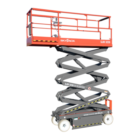
Skyjack 3226 Maintenance & Parts Manual
Sjiii series
Hide thumbs
Also See for 3226:
- Maintenance & parts manual (207 pages) ,
- Operating manual (90 pages) ,
- Maintenance & parts manual (162 pages)
Table of Contents
Advertisement
AINTENANCE &
PARTS
or Service please call ....................................................................
kyjack Inc. ervice Center, 3451 wenson Ave., t. Charles, IL. 60174 ..... AX 630 262-
or Parts in North America and Asia please call ......................................
kyjack Inc. Parts Center, 3451 wenson Ave., t. Charles, IL. 60174 ........... AX 888 782-4825
or Parts & Service in Europe please call ...................................................
kyjack Europe Glovers Meadow, Maesbury Rd. Oswestry, hropshire, UK ........... AX 44-169- 676 238
118940A
ANUAL
Printed in Canada
00 275-9522
0006
00 965-4626
44-1691-676 236
Nov. 2013
Advertisement
Chapters
Table of Contents
Troubleshooting

Related Manuals for Skyjack 3226


Summary of Contents for Skyjack 3226
- Page 1 AINTENANCE & PARTS ANUAL 00 275-9522 or Service please call ..............kyjack Inc. ervice Center, 3451 wenson Ave., t. Charles, IL. 60174 ..AX 630 262- 0006 00 965-4626 or Parts in North America and Asia please call ........kyjack Inc. Parts Center, 3451 wenson Ave., t. Charles, IL. 60174 ... AX 888 782-4825 44-1691-676 236 or Parts &...
- Page 2 TRAINING AND UNDERSTANDING O THE OPERATION O BOTH STANDARD AND OPTIONAL EQUIPMENT. DO NOT USE A WORK PLAT ORM THAT HAS OPTIONS, ALTERATIONS OR MODI ICATIONS NOT APPROVED BY SKYJACK. USE THE SERIAL NUMBER O YOUR MACHINE TO DETERMINE THE CORRECT Operating manual TO USE...
-
Page 3: Table Of Contents
TABLE OF CONTENT Section - Paragraph Page No. ection 1 About Your Aerial Platform Purpose Of Equipment ........................1 Use Of Equipment ..........................1 Scope Of This Manual ........................2 Warranty Statement .......................... 2 Warranty Procedures ........................2, 3 Operator Safety Reminders ......................4 Electrocution Hazard ........................ - Page 4 The Safety Alert Symbol identifies important safety messages on machines, safety signs in manuals This afety Alert ymbol Means Attention! or elsewhere. When you see this symbol, be alert to the possibility of personal injury or death. Fol- Become Alert! Your afety Is Involved. low the instructions in the safety message.
-
Page 5: Ection 1 - About Your Aerial Platform
Aerial Platform. A mobile device that has an adjustable position platform supported from ground level by a structure. Purpose Of Equipment. The SKYJACK SJIII series aerial platforms are designed to transport and raise personnel, tools and materials to overhead work areas. -
Page 6: Scope Of This Manual
1-2-a. Warranty tatement This manual pplies to the ANSI/SIA, CSA nd SKYJACK Inc. w rr nts e ch new eri l pl tform to be CE versions of the SJIII Series eri l pl tform free of defective p rts nd workm nship. During the models listed on (T ble 2-1.) -
Page 7: Warranty Procedures
ection 1 - About Your Aerial Platform 6. M teri ls returned for w rr nty inspection must be: 1-2-b. Warranty Procedures (Continued) 2. When Skyj ck’s Service Dep rtment verifies w rr nty C refully p ck ged to prevent ddition l cover ge, they will lso issue... -
Page 8: Operator Safety Reminders
The following p ges of this m nu l should be re d nd understood completely before oper ting the eri l pl tform. Any modific tions from the origin l design re strictly forbidden without written permission from SKYJACK Inc. 1-4. Electrocution Hazard This aerial platform is not electrically insulated. - Page 9 • DO NOT Ascend or descend gr de steeper th n 23% (3215, 3219), 25% (3220, 3226), 20% (4832) or 25% (4620, 4626, 6826 & 6832). Ascend or descend • DO NOT r ise the eri l pl tform gr des only when fully lowered in windy or gusty conditions.
- Page 10 ection 1 - About Your Aerial Platform 1-5. afety Precautions (Continued) Know And Underst nd The S fety Prec utions Before Going On To Next Section. • DO NOT oper te on surf ces not c p ble of hold- ing the weight of the eri l pl tform including the r ted lo d, e.g.
- Page 11 ection 1 - About Your Aerial Platform 1-5. afety Precautions (Continued) Know And Underst nd The S fety Prec utions Before Going On To Next Section. • DO NOT overlo d the pl tform, the lift relief v lve Jobsite Inspection. does not protect g inst overlo ding when the pl tform is elev ted.
- Page 12 ection 2 - Tables TABLE OF CONTENT List of Tables able 2-1. Specifications and Features ........................2, 3 able 2-2. Floor Loading Pressure .......................... 4, 5 able 2-3. Owner’s Annual Inspection Record ......................6 able 2-4. Maximum Platform Capacities (Evenly Distributed) ..................6 able 2-5.
- Page 13 2 - Tables Table 2-1a. pecifications and Features 3220 / 3226 / Model 3215 3219 3220m 3226m Weight 2400lbs 2580 lbs. 3510 lbs. 4135 lbs. (1088 kg) (1170 kg) (1592 kg) (1876 kg) 32.0” 32.9” Width (0.81m) (0.84m) 70.0”...
- Page 14 ection 2 - Tables Table 2-1b. pecifications and Features Model 4620 4626 4832 6826 6832 Weight 3700 lb 4940 lb 5590 lb 5380 lb 5680 lb (1678 kg) (2241 kg) (2536 kg) (2440 kg) (2576 kg) 46” 48” 68” Width (1.17 m) (1.22 m) (1.73 m)
- Page 15 9.57 2580 1170 7.03 8.14 3219 3130 1420 7.73 10.05 3490 1583 3220 3220 M 4840 1991 4110 1864 3226 3226 M 4610 2091 3660 1660 6.89 128.16 6.14 4620 4760 2159 6.68 167.04 4870 2209 6.82 171.36 8.21 4626...
- Page 16 Intermixing tires of different types or using tires of types other than those originally supplied with this equipment can adversely affect stability. Therefore, replace tires only with the exact original Skyjack- approved type. Failure to operate with matched approved tires in good condition may result in death or serious injury.
- Page 17 3220 M (227 kg) Person (136 kg) Person 250 lbs 250 lbs 3226 (113 kg) Person (113 kg) Person 3226 M 800 lbs 300 lbs 700 lbs 300 lbs 4620 (362 kg) Person (136 kg) Person (317 kg) Person (136 kg)
-
Page 18: Jiii Eries
ection 2 - Tables General Maintenance Before attempting any repair work, disconnect the battery by turning the Battery Disconnect switches to the off position. Preventative maintenance is the easiest and least expensive type of maintenance. Table 2-5. Maintenance And Inspection chedule Daily Weekly Monthly... - Page 19 Figure 3-28. Hydraulic Schematic Parts List ................69 Figure 3-29. Hydraulic Schematic (Models 3220 & 4620) ............71 Figure 3-30. Hydraulic Schematic (Model 3226, 4626 & 48XX) ..........72 Figure 3-31. Hydraulic Schematic (Models 6826 & 6832) ............73 8940...
-
Page 20: Jiii Eries
Figure 3-1. Relay Function Chart UPPLY (B+) (Common) CONTROL (B+) GROUND (B-) NORMALLY NORMALLY CLO ED OPEN CONTACT CONTACT RELAY NO. RELAY FUNCTION 13BCR LWS MO ULE TIME ELAY CUTOUT (CE) 17CR TRANSFER RELAY 21CR PROPORTIONAL RELAY (Machines with no options) 21ACR PROPORTIONAL RELAY (Machines with options) 28CR... -
Page 21: Jiii Eries
Figure 3-2. ilt Switch Usage Chart AN I MODEL CE MODEL Tilt switches Tilt switches erial Numbers erial Numbers 117880 124138 118058 118091 310585 124138 (2.5 x 4.5 ) (1.5 x 3.5 ) (1 x 2 ) (2 x 2 ) (2 x 4 ) (1.5 x 3.5 ) From 609331 to... -
Page 22: Jiii Eries
Figure 3-3. Electrical Symbol Chart WIRE CROSSING HOURMETER KEY SWITCH WIRES JOINE LIGHT FOOT SWITCH HY RAULIC BATTERY TOGGLE SWITCH VALVE COIL PROPORTIONAL HY RAULIC GROUN PUSH BUTTON VALVE COIL ELECTRIC MOTOR FUSE ROTARY SWITCH CIRCUIT BREAKER HORN LIMIT SWITCH BATTERY EMERGENCY CAM OPERATE... -
Page 23: Jiii Eries
Figure 3-4. Hydraulic Symbol Chart VARIABLE SHUTTLE VALVE VELOCITY FUSE LINE CROSSING ISPLACEMENT PUMP ACCUMULATOR, SINGLE ACTING LINE JOINE PUMP GAS CHARGE CYLIN ER HY RAULIC CUSHION OUBLE ACTING RELIEF VALVE TANK CYLIN ER CYLIN ER PRESSURE HY RAULIC OUBLE ACTING PRESSURE RE UCING FILTER WITH... -
Page 24: Jiii Eries
Figure 3-5a. Control Box Diagram - With Horn (ANSI/SIA And CSA) (Refer o Serial Number Chart On he Diagram) erial Number Model Number From 3220 61499 609331 4620 66561 66430 4626 705463 704419 4830 873312 86983 4832 87320 86983 6826 75550 75518 6832... -
Page 25: Jiii Eries
Figure 3-5a. Control Box Parts List - With Horn (ANSI/SIA And CSA) (Refer o Serial Number Chart On he Diagram) Index kyjack Qty. Description Part No. 119642 CABLE ASSEMBLY, Control box 103012 BLOCK, 12 Pole terminal 115311 CONTROLLER ASSEMBLY, Proportional 122093 BATTERY CHARGE IN ICATOR (Ref.) -
Page 26: Jiii Eries
Figure 3-5b. Control Box Diagram - With Horn (ANSI/SIA And CSA) (Refer o Serial Number Chart On he Diagram) erial Number Model Number From 3220 611286 61500 4620 66658 66562 4626 706174 705484 4830 87564 873313 4832 87654 87321 6826 75578 75551 6832... -
Page 27: Jiii Eries
Figure 3-5b. Control Box Parts List - With Horn (ANSI/SIA And CSA) (Refer o Serial Number Chart On he Diagram) Index kyjack Qty. Description Part No. 119642 CABLE ASSEMBLY, Control box 103012 BLOCK, 12 Pole terminal 115311 CONTROLLER ASSEMBLY, Proportional 122093 BATTERY CHARGE IN ICATOR (Ref.) -
Page 28: Jiii Eries
Figure 3-5c. Control Box Diagram - With Horn (ANSI/SIA And CSA) erial Number Model Number From 3220 Above 611287 4620 Above 66659 4626 Above 706175 4830 Above 87565 4832 Above 87655 6826 Above 75579 6832 Above 82754 8940 ECTION 3, Page 10 JIII eries - he Conventionals ov. -
Page 29: Jiii Eries
Figure 3-5c. Control Box Parts List - With Horn (ANSI/SIA And CSA) Index kyjack Qty. Description Part No. 119642 CABLE ASSEMBLY, Control box 103012 BLOCK, 12 Pole terminal 122840 CONNECTOR ASSEMBLY, Male 9 pole 116993 • HOUSING, Connector Male 9 pole 116990 •... -
Page 30: Jiii Eries
Figure 3-6a. Control Box Diagram - With All Options (ANSI/SIA And CSA) (Refer o Serial Number Chart On he Diagram) erial Number Model Number From 3220 61499 609331 4620 66561 66430 4626 705463 704419 4830 873312 86983 4832 87320 86983 6826 75550 75518... -
Page 31: Jiii Eries
Figure 3-6a. Control Box Parts List - With All Options (ANSI/SIA And CSA) (Refer o Serial Number Chart On he Diagram) Index kyjack Qty. Description Part No. 119731 CABLE ASSEMBLY, Control box 103012 BLOCK, 12 Pole terminal 115311 CONTROLLER ASSEMBLY, Proportional 122093 BATTERY CHARGE IN ICATOR (Ref.) -
Page 32: Jiii Eries
Figure 3-6b. Control Box Diagram - With All Options (ANSI/SIA And CSA) (Refer o Serial Number Chart On he Diagram) erial Number Model Number From 3220 611286 61500 4620 66658 66562 4626 706174 705464 4830 87564 873313 4832 87564 87321 6826 75578 75551... -
Page 33: Jiii Eries
Figure 3-6b. Control Box Parts List - With All Options (ANSI/SIA And CSA) (Refer o Serial Number Chart On he Diagram) Index kyjack Qty. Description Part No. 119731 CABLE ASSEMBLY, Control box 103012 BLOCK, 12 Pole terminal 115311 CONTROLLER ASSEMBLY, Proportional 122093 BATTERY CHARGE IN ICATOR (Ref.) -
Page 34: Jiii Eries
Figure 3-6c. Control Box Diagram - With All Options (ANSI/SIA And CSA) erial Number Model Number From 3220 Above 611287 4620 Above 66659 4626 Above 706175 4830 Above 87565 4832 Above 87655 6826 Above 75579 6832 Above 82754 8940 ECTION 3, Page 16 JIII eries - he Conventionals ov. -
Page 35: Jiii Eries
Figure 3-6c. Control Box Parts List - With All Options (ANSI/SIA And CSA) Index kyjack Qty. Description Part No. 119731 CABLE ASSEMBLY, Control box 103012 BLOCK, 12 Pole terminal 122840 CONNECTOR ASSEMBLY, Male 9 pole 116993 • HOUSING, Connector Male 9 pole 116990 •... -
Page 36: Jiii Eries
Figure 3-7. Control Box Diagram - With Horn (ANSI/SIA And CSA)(EE Rating) 11032AA 8940 ECTION 3, Page 18 JIII eries - he Conventionals ov. 2013... -
Page 37: Jiii Eries
Figure 3-7. Control Box Parts List - With Horn (ANSI/CSA And CSA)(EE Rating) Index kyjack Qty. Description Part No. 119737 CABLE ASSEMBLY, Control box 103012 BLOCK, 12 Pole terminal 122840 CONNECTOR ASSEMBLY, Male 9 pole 116993 • HOUSING, Connector Male 9 pole 116990 •... -
Page 38: Jiii Eries
Figure 3-8a. Control Box Diagram - With Horn (CE) (Refer o Serial Number Chart On he Diagram) erial Number Model Number From 3220 61499 609331 4620 66561 66430 4626 705463 704419 4830 873312 86983 4832 87320 86983 6826 75550 75518 6832 82641 82403... -
Page 39: Jiii Eries
Figure 3-8a. Control Box Parts List - With Horn (CE) (Refer o Serial Number Chart On he Diagram) Index kyjack Qty. Description Part No. 119731 CABLE ASSEMBLY, Control box 103012 BLOCK, 12 Pole terminal 115311 CONTROLLER ASSEMBLY, Proportional 122093 BATTERY CHARGE IN ICATOR (Ref.) SWITCH ASSEMBLY, Key base/off/platform, 103082... -
Page 40: Jiii Eries
Figure 3-8b. Control Box Diagram - With Horn (CE) (Refer o Serial Number Chart On he Diagram) erial Number Model Number From 3220 611286 61500 4620 66658 66562 4626 706174 705464 4830 87564 87313 4832 87564 87321 6826 75578 75551 6832 82753 82642... -
Page 41: Jiii Eries
Figure 3-8b. Control Box Parts List - With Horn (CE) (Refer o Serial Number Chart On he Diagram) Index kyjack Qty. Description Part No. 119731 CABLE ASSEMBLY, Control box 103012 BLOCK, 12 Pole terminal 115311 CONTROLLER ASSEMBLY, Proportional 122093 BATTERY CHARGE IN ICATOR (Ref.) SWITCH ASSEMBLY, Key base/off/platform, 103082... -
Page 42: Jiii Eries
Figure 3-8c. Control Box Diagram - With Horn (CE) (Refer o Serial Number Chart On he Diagram) erial Number Model Number From 3220 611287 Above 4620 66659 Above 4626 706175 Above 4830 87565 Above 4832 Above 87565 6826 Above 75579 6832 82754 Above... -
Page 43: Jiii Eries
Figure 3-8c. Control Box Parts List - With Horn (CE) (Refer o Serial Number Chart On he Diagram) Index kyjack Qty. Description Part No. 119731 CABLE ASSEMBLY, Control box 103012 BLOCK, 12 Pole terminal 122840 CONNECTOR ASSEMBLY, Male 9 pole 116993 •... -
Page 44: Jiii Eries
Figure 3-9a. Control Box Diagram - With All Options (CE) (Refer o Serial Number Chart On he Diagram) erial Number Model Number From 3220 61499 609331 4620 66561 66430 4626 705463 704419 4830 87312 86983 4832 87320 86983 6826 75550 75518 6832 82641... -
Page 45: Jiii Eries
Figure 3-9a. Control Box Parts List - With All Options (CE) (Refer o Serial Number Chart On he Diagram) Index kyjack Qty. Description Part No. 119731 CABLE ASSEMBLY, Control box 103012 BLOCK, 12 Pole terminal 115311 CONTROLLER ASSEMBLY, Proportional 122093 BATTERY CHARGE IN ICATOR (Ref.) SWITCH ASSEMBLY, Key off/on... -
Page 46: Jiii Eries
Figure 3-9b. Control Box Diagram - With All Options (CE) (Refer o Serial Number Chart On he Diagram) erial Number Model Number From 3220 611286 61500 4620 66658 66562 4626 706174 705464 4830 87564 87313 4832 87564 87321 6826 75578 75551 6832 82753... -
Page 47: Jiii Eries
Figure 3-9b. Control Box Parts List- With All Options (CE) (Refer o Serial Number Chart On he Diagram) Index kyjack Qty. Description Part No. 119731 CABLE ASSEMBLY, Control box 103012 BLOCK, 12 Pole terminal 115311 CONTROLLER ASSEMBLY, Proportional 122093 BATTERY CHARGE IN ICATOR (Ref.) SWITCH ASSEMBLY, Key off/on 103082... -
Page 48: Jiii Eries
Figure 3-9c. Control Box Diagram - With All Options (CE) (Refer o Serial Number Chart On he Diagram) erial Number Model Number From 3220 611287 Above 4620 66659 Above 4626 706175 Above 4830 87565 Above 4832 87565 Above 6826 Above 75579 6832 Above... -
Page 49: Jiii Eries
Figure 3-9c. Control Box Parts List- With All Options (CE) (Refer o Serial Number Chart On he Diagram) Index kyjack Qty. Description Part No. 119731 CABLE ASSEMBLY, Control box 103012 BLOCK, 12 Pole terminal 122840 CONNECTOR ASSEMBLY, Male 9 pole 116993 •... -
Page 50: Jiii Eries
Description Part No. 130440 TRANS UCER, Angle If Equipped) B1-B4 BATTERY, 6 Volt (Trojan #T2200) Models 3220, 3226, 4620 & 4626) BATTERY, 6 Volt (Trojan #J250) Model 4830 & 4832) 112255 BATTERY CHARGER ASSEMBLY (Bycan #2440A) 113415 BATTERY CHARGER ASSEMBLY (Bycan #2440E) -
Page 51: Jiii Eries
3H-18A 103605 COIL, 24 Volt (Pilot Valve) Models 68XX) 3H-18A1 103605 COIL, 24 Volt (speed A) Models 3220, 3226, 4620, 4626, 4830 & 4832) 3H-18A2 103605 COIL, 24 Volt (speed B) Models 3220, 3226, 4620, 4626, 4830 & 4832) 4H-15... -
Page 52: Jiii Eries
Figure 3-10. Electrical Schematic Parts List (Continued) Index kyjack Qty. Description Part No. Parts list continued from the previous page. 118717 LWS MO ULE 102863 PRESSURE SWITCH 117150 • CIRCUIT BOAR ASSEMBLY RST1 119629 RESISTOR, 2.7K RST2 115313 RESISTOR, 25W-30 Ohm Models 32XX, 46XX, 48XX, 6832) (Order P/N 120174 for Machines with Serial No. -
Page 53: Jiii Eries
Figure 3-11a. Electrical Schematic - No Options (ANSI/SIA And CSA) (Refer o Serial Number Chart Below) erial Number Model Number From 3220 610225 609331 4620 66550 66430 4626 705266 704419 4830 87243 86983 4832 87243 86983 6826 75549 75518 6832 82584 82403 SS-1105AC-1... -
Page 54: Jiii Eries
Figure 3-11b. Electrical Schematic - No Options (ANSI/SIA And CSA) (Refer o Serial Number Chart Below) erial Number Model Number From 3220 610499 610226 4620 66561 66551 4626 705463 705267 4830 873312 87244 4832 87320 87244 6826 75551 75550 6832 82641 82585 SS-1105AD-1... -
Page 55: Jiii Eries
Figure 3-11c. Electrical Schematic - No Options (ANSI/SIA And CSA) (Refer o Serial Number Chart Below) erial Number Model Number From 3220 611286 610500 4620 66658 66562 4626 706174 705464 4830 87564 873313 4832 87564 87321 6826 75578 75552 6832 82753 82642 SS-1105AE-1... -
Page 56: Jiii Eries
Figure 3-11d. Electrical Schematic - No Options (ANSI/SIA And CSA) (Refer o Serial Number Chart Below) erial Number Model Number From 3220 Above 611287 4620 Above 66659 4626 Above 706175 4830 Above 87565 4832 Above 87655 6826 Above 75579 6832 82754 Above SS-1105AF... -
Page 57: Jiii Eries
Figure 3-12a. Electrical Schematic - All Options (ANSI/SIA And CSA) (Refer o Serial Number Chart Below) erial Number Model Number From 3220 609331 610225 4620 66430 66550 4626 705266 704419 4830 86983 87243 4832 86983 87243 6826 75518 75549 6832 82403 82584 50057AA... -
Page 58: Jiii Eries
Figure 3-12b. Electrical Schematic - All Options (ANSI/SIA And CSA) (Refer o Serial Number Chart Below) erial Number Model Number From 3220 610499 610226 4620 66561 66551 4626 705463 705267 4830 873312 87244 4832 87320 87244 6826 75551 75550 6832 82641 82585 50058AA... -
Page 59: Jiii Eries
Figure 3-12c. Electrical Schematic - All Options (ANSI/SIA And CSA) (Refer o Serial Number Chart Below) erial Number Model Number From 3220 610500 611286 4620 66562 66658 4626 706174 705464 4830 873313 87564 4832 87321 87564 6826 75552 75578 6832 82642 82753 50059AA... -
Page 60: Jiii Eries
Figure 3-12d. Electrical Schematic - All Options (ANSI/SIA And CSA) (Refer o Serial Number Chart Below) erial Number Model Number From 3220 611287 Above 4620 66659 Above 4626 Above 706175 4830 87565 Above 4832 Above 87655 6826 Above 75579 6832 Above 82754 50060AD... -
Page 61: Jiii Eries
Figure 3-13a. Electrical Schematic - Models 32xx, 4620, 4626 & 48xx With All Options (CE) (Refer o Serial Number Chart Below) erial Number Model Number From 3220 609331 610225 4620 66430 66550 4626 705266 704419 4830 86983 87243 4832 86983 87243 6826 75518... -
Page 62: Jiii Eries
Figure 3-13b. Electrical Schematic - Models 32xx, 4620, 4626 & 48xx With All Options (CE) (Refer o Serial Number Chart Below) erial Number Model Number From 3220 610499 610226 4620 66561 66551 4626 705463 705267 4830 87312 87244 4832 87320 87244 6826 75551... -
Page 63: Jiii Eries
Figure 3-13c. Electrical Schematic - Models 32xx, 4620, 4626 & 48xx With All Options (CE) (Refer o Serial Number Chart Below) erial Number Model Number From 3220 611286 610500 4620 66658 66562 4626 706174 705464 4830 87564 87313 4832 87564 87321 6826 75578... -
Page 64: Jiii Eries
Figure 3-13d. Electrical Schematic - Models 32xx, 4620, 4626 & 48xx With All Options (CE) (Refer o Serial Number Chart Below) erial Number Model Number From 3220 611287 Above 4620 66659 Above 4626 706175 Above 4830 87565 Above 4832 87565 Above 50142AA 8940... -
Page 65: Jiii Eries
Figure 3-14a. Electrical Schematic - Models 6826 And 6832 With All Options (CE) (Refer o Serial Number Chart Below) erial Number Model Number From 3220 609331 610225 4620 66430 66550 4626 705266 704419 4830 86983 87243 4832 86983 87243 6826 75518 75549 6832... -
Page 66: Jiii Eries
Figure 3-14b. Electrical Schematic - Models 6826 And 6832 With All Options (CE) (Refer o Serial Number Chart Below) erial Number Model Number From 3220 610499 610226 4620 66561 66551 4626 705463 705267 4830 87312 87244 4832 87320 87244 6826 75551 75550 6832... -
Page 67: Jiii Eries
Figure 3-14c. Electrical Schematic - Models 6826 And 6832 With All Options (CE) (Refer o Serial Number Chart Below) erial Number Model Number From 3220 611286 610500 4620 66658 66562 4626 706176 705464 4830 87564 87313 4832 87564 87321 6826 75578 75552 6832... -
Page 68: Jiii Eries
Figure 3-14d. Electrical Schematic - Models 6826 And 6832 With All Options (CE) (Refer o Serial Number Chart Below) erial Number Model Number From 6826 Above 75579 6832 Above 82754 SS-1119AC 8940 ECTION 3, Page 50 JIII eries - he Conventionals ov. -
Page 69: Jiii Eries
ELECTRICAL PANEL - EE With All Options ANSI/SIA and CSA) Ref.) ELECTRICAL PANEL - All Options CE) 119348 LIMIT SWITCH, Pothole protection Models 3220, 3226, 4620, 4626, 4830 & 4832) 103743 FLASHER, 12-24 Volt optional), B, C & D 115313 RESISTOR. -
Page 70: Jiii Eries
119759 JUMPER, 68XX LWS, 118722 JUMPER, 68XX LWS Flashing Light Option), 121993 HARNESS, Base Control Box And Tilt Model 3220 & 3226), 121994 HARNESS, Base Control Box And Tilt Models 46XX, 48XX & 68XX), 117967 BEEPER, Lowering warning system, 105534... -
Page 71: Jiii Eries
Figure 3-16a. Electrical Panel Diagram - No Options (ANSI/SIA And CSA) (Refer o Serial Number Chart Below) erial Number Model Number From 3220 610225 609331 4620 66550 66430 4626 705266 704419 4830 87243 86983 4832 87243 86983 6826 75499 75518 6832 82584 82403... -
Page 72: Jiii Eries
Figure 3-16b. Electrical Panel Diagram - No Options (ANSI/SIA And CSA) (Refer o Serial Number Chart Below) erial Number Model Number From 3220 Above 610226 4620 Above 66551 4626 Above 705267 4830 Above 87244 4832 Above 87244 6826 Above 75500 6832 Above 82585... -
Page 73: Jiii Eries
Figure 3-17a. Electrical Panel Diagram - All Options (ANSI/SIA And CSA) (Except EE Rating) (Refer o Serial Number Chart Below) erial Number Model Number From 3220 610225 609331 4620 66430 66550 4626 705266 704419 4830 87243 86983 4832 87243 86983 6826 75499 75518... -
Page 74: Jiii Eries
Figure 3-17b. Electrical Panel Diagram - All Options (ANSI/SIA And CSA)(Except EE Rating) (Refer o Serial Number Chart Below) erial Number Model Number From 3220 Above 610226 4620 Above 66551 4626 Above 705267 4830 Above 87244 4832 Above 87244 6826 Above 75500 6832... -
Page 75: Jiii Eries
Figure 3-18. Electrical Panel Diagram - All Options (ANSI/SIA And CSA) (EE Rating) 50240AA 8940 JIII eries - he Conventionals ECTION 3, Page 57 ov. 2013... -
Page 76: Jiii Eries
Figure 3-19a. Electrical Panel Diagram - All Options (CE) (Refer o Serial Number Chart Below) erial Number Model Number From 3220 610225 609331 4620 66550 66430 4626 705266 704419 4830 87243 86983 4832 87243 86983 6826 75499 75518 6832 82584 82403 SP-1007AB 8940... -
Page 77: Jiii Eries
Figure 3-19b. Electrical Panel Diagram - All Options (CE) (Refer o Serial Number Chart Below) erial Number Model Number From 3220 613550 610226 4620 66889 66551 4626 709588 705267 4830 871159 87244 4832 871159 87244 6826 Not Available 75500 6832 83073 82585 50241AA... -
Page 78: Jiii Eries
Figure 3-20. Battery Charger Schematic - Motor Appliance #Ba610 Chrgsj3 Index kyjack Qty. Description Part No. 08592 BATTERY CHARGER ASSEMBLY, 24V40A, 20VAC, 60Hz 09 02 • CAPACITOR 09 08 • TRANSFORMER 53 5 • RELAY, Charger cutout 20 VAC • PLUG, Charger cutout 7 77 •... -
Page 79: Jiii Eries
Figure 3-21. Battery Charger Schematic - Motor Appliance #Ba 1044 SS-1109 Index kyjack Qty. Description Part No. 9863 CHARGER ASSEMBLY, Battery (BA 044)(ANSI/SIA , CSA and CE) 9 44 • VARISTOR ASSEMBLY 9 55 • RELAY, 24VDC 30A 9 56 •... -
Page 80: Jiii Eries
Figure 3-22. Battery Charger Schematic Parts List - Bycan #2440a And 2440e Bycansch Index kyjack Qty. Description Part No. 2255 BATTERY CHARGER ASSEMBLY, 24V40A, 220VAC, 60 Hz 34 5 BATTERY CHARGER ASSEMBLY, 24V40A, 220VAC, 50-60 Hz 7 62 • AMMETER, 50 Amp 7 63 •... -
Page 81: Jiii Eries
Figure 3-23. Battery Charger Schematic Parts List - Bycan #2440u SS-1124AA Index kyjack Qty. Description Part No. 2 485 CHARGER ASSEMBLY, Battery (2440U, 50/60 Hz) 2 570 VARISTOR 2 535 TRANSFORMER 2 536 CAPACITOR 2 569 RESISTOR 0K OHM, 3W 2 538 RECTIFIER 58 7... -
Page 82: Jiii Eries
Figure 3-24. Electrical Inverter Option: Schematic & Panel Diagram - All models except with Load Sensing (Without imer Cut-out Relay) Electrical Schematic 50221AA Electrical Panel Diagram Note: Refer to Figure 3-10 for Parts Listing 11199AA 8940 ECTION 3, Page 65 JIII eries - he Conventionals ov. -
Page 83: Jiii Eries
Figure 3-25. Electrical Inverter Option: Schematic & Panel Diagram - ANSI/CSA (Equipped with imer Cut-out Relay) Electrical Schematic 50222AA Electrical Panel Diagram Note: Refer to Figure 3-10 for Parts Listing 11154AA 1 8940 ECTION 3, Page 66 JIII eries - he Conventionals ov. -
Page 84: Jiii Eries
Figure 3-26. Electrical Inverter Option: Schematic & Panel Diagram - CE with Load Sensing System (Equipped with imer Cut-out Relay) Electrical Schematic 50222AA Electrical Panel Diagram 11155AB Note: Refer to Figure 3-10 for Parts Listing 8940 ECTION 3, Page 67 JIII eries - he Conventionals ov. -
Page 85: Jiii Eries
Figure 3-27. Hydraulic Manifold Component Identification 2H-18A 3H-18A DIFFERENTIAL PILOT VALVE VALVE 3H-18A-2 PEED VALVE B REAR DRIVE MANIFOLD FLOW REAR DIVIDER/COMBINER DRIVE VALVE MANIFOLD FREE-WHEELING 2H-59B VALVE PROPORTIONAL VALVE 3H-18A-1 CHECK CHECK PEED VALVE VALVE VALVE A CMP1 PROPORTIONAL COMPEN ATOR 3H-14 VALVE... -
Page 86: Jiii Eries
Figure 3-28 Hydraulic Schematic Parts List Index kyjack Qty. Description Part No. 2429 CYLINDER, Cushion 20989 CYLINDER, Lift 2 965 CYLINDER, Lift 4830) 20236 CYLINDER, Steer 20240 CYLINDER, Steer 68XX) 20220 CYLINDER, Brake 20262 CYLINDER, 6 FT Powered extension platform 20255 CYLINDER, 5 FT Powered extension platform 68XX) 04 33... -
Page 87: Jiii Eries
FIGURE 3-28. HYDRAULIC SCHEMA IC PAR S LIS (CON INUED) Index kyjack Qty. Description Part No. Parts list continued from previous page. 03 29 MOTOR, Hydraulic drive LH (White Hydraulics) 02689 MOTOR, Hydraulic drive LH (White Hydraulics) 68XX) 03 29 MOTOR, Hydraulic drive RH (White Hydraulics) 02689 MOTOR, Hydraulic drive RH (White Hydraulics) 68XX) -
Page 88: Jiii Eries
Figure 3-29. Hydraulic Schematic (Models 3220 & 4620) 50075AD 8940 JIII eries - he Conventionals ECTION 3, Page 71 ov. 2013... -
Page 89: Jiii Eries
Figure 3-30. Hydraulic Schematic (Model 3226, 4626 And 48xx) 50074AD 8940 ECTION 3, Page 72 JIII eries - he Conventionals ov. 2013... -
Page 90: Jiii Eries
Figure 3-31. Hydraulic Schematic (Models 6826 & 6832) 50149AE 8940 JIII eries - he Conventionals ECTION 3, Page 73 ov. 2013... - Page 91 ection 4 Troubleshooting Information Table Of Contents Introduction ..............................2 Electrical ystem .1-1. All Controls Inoperative ........................3 .1-2. All Controls Inoperative From Platform (Machines Without Power Deck) ..........3 .1-3. All Controls Inoperative From Platform (Machines With Power Deck) ...........1- .
-
Page 92: Kyjack
Troubleshooting Information - Introduction The following pages contain a Table of Troubleshooting information for locating and correcting most service trouble which can develop. Careful inspection and accurate analysis of the systems listed in the Table of Trouble- shooting Information will localize the trouble more quickly than any other method. This manual cannot cover all possible troubles and deficiencies that may occur. -
Page 93: Jiii Eries
Troubleshooting Information - Electrical ystem Probable Cause Remedy 4.1-1. All Controls Inoperative 1. Battery Charger plugged into external power source. 1. Disconnect charger cord. 2. Batteries disconnected. 2. Connect batteries. 3. Dirty or loose battery terminals. 3. Clean and tighten connections. . -
Page 94: Jiii Eries
Troubleshooting Information - Electrical ystem Probable Cause Remedy 4.1-3. All Controls Inoperative From Platform (Machines With Power Deck) 1. Loose or broken wire #07 from Base Terminal Block 1. Check continuity. Replace if defective. (TB-1) to Platform Emergency Stop Switch (S ). 2. -
Page 95: Jiii Eries
Troubleshooting Information - Electrical ystem Probable Cause Remedy 4.1-8. No Up Function From Platform Or Base Controls (Machines Equipped With Tilt Cut-out Options) 1. Machine not level. 1. Use on level surface. 2. Loose or broken wire 19 from Base Terminal Block 2. -
Page 96: Jiii Eries
Troubleshooting Information - Electrical ystem Probable Cause Remedy 4.1-10. Lowering Warning ystem Inoperative (CE Machines Only) 1. Loose or broken wire #10A from Base Terminal 1. Check continuity. Replace if defective. Block (TB-1) to Lowering Warning System Module (LWS1). 2. Loose or broken wire #02 from Base Terminal Block 2. -
Page 97: Jiii Eries
Troubleshooting Information - Electrical ystem Probable Cause Remedy 4.1-16. No Drive Or teer When Platform Elevated (All Machines) 1. Pot Hole Protection Bars not fully lowered. 1. Clear obstructions. Repair as needed. 2. Loose or broken wire #71 from Base Terminal Block 2. -
Page 98: Jiii Eries
Troubleshooting Information - Electrical ystem Probable Cause Remedy 4.1-19. Left teer Inoperative (Machines Without Powered Platform) 1. Defective Steer Left Switch (S73). 1. Check switch. Replace if defective. 2. Loose or broken wire #2 from Steer Left Switch 2. Check continuity. Replace if defective. (S73) to Lift/Drive Select Switch (S5). -
Page 99: Jiii Eries
Troubleshooting Information - Electrical ystem Probable Cause Remedy 4.1-23. Work Platform Drives In low peed Only 1. Loose or broken wire #71 from Base Terminal Block 1. Check continuity. Replace if defective. (TB-1) to High Speed Limit Switch (LS1). 2. Open or defective High Speed Limit Switch (LS1). 2. -
Page 100: Jiii Eries
Troubleshooting Information - Electrical ystem Probable Cause Remedy 4.1-28. Lift Down Inoperative From Base Controls 1. Defective Up/Down Switch (S2). 1. Check switch. Replace if defective. 2. Loose or broken wire #13 from Up/Down Switch 2. Check continuity. Replace if defective. (S2) to Base Terminal Block (TB-1). -
Page 101: Jiii Eries
Troubleshooting Information - Electrical ystem Probable Cause Remedy 4.1-33. High/Low Torque Inoperative 1. Open Diode (D15-1). (Reverse) or (D16-1) 1. Check diode. Replace if defective. (Forward). 2. Loose or broken wire #18 from Diodes (D15-1) and 2. Check continuity. Replace if defective. (D16-1) to High/Low Torque (S27). -
Page 102: Jiii Eries
Troubleshooting Information - Hydraulic ystem Probable Cause Remedy 4.2-1. All Functions Inoperative 1. Proportional Valve (2H-59B) defective or is sticking. 1. Check valve. Replace if defective. 2. Compensator Valve (CMP1) defective or is sticking. 2. Check valve. Replace if defective. 3. -
Page 103: Jiii Eries
Troubleshooting Information - Hydraulic ystem Probable Cause Remedy 4.2-9. Platform Does Not teer 1. Right Steer Valve ( H-23A) or Left Steer Valve ( H- 1. Clean valve. Replace if defective. 2 A) defective or sticking. 2. Steer Cylinder (C3) seals leaking. 2. -
Page 104: Jiii Eries
ECTION 5 Table Of Contents escription Page No. Operators Responsibility For Maintenance ....................2 Maintenance And Inspection Schedule ....................... 2 Owners Annual Inspection Record ......................2 General Maintenance Hints ......................... 2 Hydraulic System And Component Maintenance And Repair ..............3 General Specifications .......................... -
Page 105: Operators Responsibility For Maintenance
Operator’s Responsibility For Maintenance And Inspection Maintenance chedule eath or injury can result if the work platform is not The actual operating environment of the work kept good working order. Inspection platform governs the use of the maintenance maintenance should be performed by competent schedule. -
Page 106: Hydraulic System And Component Maintenance And Repair
For conditions oil of the proper type and viscosity in the causing oil temperatures below -31°F (-35°C) hydraulic reservoir. and above 122°F (50°C) consult Skyjack, Inc. Keep all connections tight. 8940 JIII eries - he Conventionals ECTION 5, Page 3 ov. -
Page 107: Jiii Eries
Table 5-1. General pecifications Model 3220 3226 4620 4626 4832 6826 6832 Electrical 24 Volts C 24 Volts C 24 Volts C 24 Volts C 24 Volts C 24 Volts C 24 Volts C ystem 220AH 220AH 220AH 220AH 6V Batteries... -
Page 108: Jiii Eries
Table 5-2. Torque pecifications 28-32 lbf.in 2.16 – 3.61 Nm irectional valve mounting bolts 90 lbf.ft 122.02 Nm Wheel mounting bolts (32XX, 46XX & 48XX) Wheel mounting bolts (68XX) 90 lbf.ft 122.04 Nm Wheel motor castle nut (32XX, 46XX & 48XX) 200 lbf.ft 271.20 Nm Wheel motor castle nut (68XX) -
Page 109: System And Lift Pressure Adjustments
ystem And Lift Pressure Adjustments All adjustments must be made with a Calibrated Gauge. Refer to the Serial Number Plate located on the rear of the machine for System and Lift Pressure values. ystem Relief Pressure Adjustment Locate the System Pressure Quick isconnect Port on the Main Manifold. -
Page 110: Controller Troubleshooting Procedure
Controller Troubleshooting Procedure POTENTIOMETER NEUTRAL STEP 8 SWITCH S7-1 (OUTSI E) STEP 6 STEP 4 STEP 3 STEP 5 STEP 10 STEP 11 igure 5-1. Proportional Controller Remove the bottom cover from the platform control box. Select “ RIVE” with Lift\ rive Select Switch (S5). Locate the “GN ”... -
Page 111: Controller Adjustment Procedure
Controller Adjustment Procedure NOTE: escribed are two accepted methods to adjust the proportional controller. Method #1 requires a Volt\Ohm meter capable of reading milliamperes. If a meter is not available, use Method #2. Method #1 Note Jack up drive axle until drive tires clear the ground. Chock other tires to prevent machine from moving. Remove the bottom cover from the platform control box. -
Page 112: Jiii Eries
Controller Adjustment Procedure Method #1 STEP #7 STEP #2 VOM METER BLACK WIRE #18 STEP #4 STEP #3 LO = 210ma (.21 AMPS) HI = 680ma (.68 AMPS) STEP #8 STEP #10 STEP #11 Figure 5-2. Proportional Controller Adjustment Method #2 STEP #4 STEP #5 STEP #6... -
Page 113: Oem Joystick Electronics Information
OEM Joystick Electronics Information Flow Control Single coil or solenoid for single direction. The coil has two connections; one is wired to the P .C. Board (A) terminal and the other is wired to (-), or the negative side of the supply voltage. Switches to control direc- tional valves may be provided on the controller. -
Page 114: Oem Joystick - Troubleshooting Procedures
OEM Joystick - Troubleshooting Procedures Problem The function will not operate when the handle is moved. The LE s do not light Check that voltage is present at the positive (+)input terminal. Check that ground is connected to the negative (-) terminal. If there is an in-line fuse, check to see if it is good. -
Page 115: Jiii Eries
Figure 5-1. OEM Joystick Harness Connector ECTION 5, Page 12 JIII eries - he Conventionals 118940 ov. 2013... -
Page 116: Jiii Eries
Figure 5-2. OEM Joystick witch Wiring Wire Chart Color From White/Red Steer Left Pin #1 White/Green +24V Steer Common Pin #2 White Steer Right Pin #3 Yellow Forward/Up (S2-NO) Pin #4 White/Black +24V Input Pin #5 Gray Reverse/ own (S1-NO) Pin #6 Blue PWM Out (A) -
Page 117: Jiii Eries
How To Order Repair Parts shown in the illustration, followed by a full description 1. Address all orders to your local SKYJACK dealer. based upon the “NOUN FIRS ” method. hat is, the noun 2. Specify model and serial number of the work name of the part is listed first, then the modifying platform (found on the serial number plate). -
Page 118: Jiii Eries
Holding Valve Assembly - Lift Cylinder ................72,73 Figure 6-19. Scissor Arm Assembly - 3220, And 4620 ................74 Figure 6-20. Scissor Arm Assembly - 3226, 4626 And 6826..............78 Figure 6-21. Scissor Arm Assembly - 4830, 4832 And 6832 ..............82 Figure 6-22. -
Page 119: Jiii Eries
6-57b. Labels - Operator’s Control Box ..................171 Figure 6-58. Labels And Nameplates - Misc................... 172 Figure 6-59a. Labels And Nameplates - Chassis (Old Skyjack logo) ............. 176 Figure 6-59b. Labels And Nameplates - Chassis (New Skyjack logo) ............ 178 8940 JIII eries - he Conventionals ECTION 6, Page 3 ov. -
Page 120: Jiii Eries
Figure 6-1a. Gate Options (Refer o Serial Number Chart On he Diagram) Model Number erial Number 3220 613550 & Below 4620 66875 & Below 4626 709340 & Below 870756 to 870770 4832 870751 & Below 6826 75618 & Below 6832 83066 &... -
Page 121: Jiii Eries
Figure 6-1a. Gate Options (Refer o Serial Number Chart On he Diagram) Index kyjack Qty. Description Part No. (Ref.) HALF GATE OPTION Model 3220 ANSI/SIA and CSA with rigid railings) (Ref.) HALF GATE OPTION Model 32XX ANSI/SIA and CSA w/hinged railings) (Ref.) HALF GATE OPTION Model 3220 CE with rigid railings) -
Page 122: Jiii Eries
Figure 6-1b. Gate Options (Refer o Serial Number Chart On he Diagram) Model Number erial Number 4620 66876 & Above 4626 709341 & Above 870752, 753, 754, 755 and 4832 870771 & Above 6826 75619 & Above 6832 83067 & Above 11031AA ECTION 6, Page 6 JIII eries - he Conventionals... -
Page 123: Jiii Eries
Figure 6-1b. Gate Options (Refer o Serial Number Chart On he Diagram) Index kyjack Qty. Description Part No. 128473 WEL MENT, Full gate Hinged (Top) 100702 PLUG, Tube 124548 PIN, Quick release large loop assembly 100509 • PIN, Quick release 3/8” dia. x 2” 105807 •... -
Page 124: Jiii Eries
Figure 6-2. Main Platform And Railings - Model 32xx (For Machines With Serial Number 613550 & Below) 17 18 S3F-1001AB ECTION 6, Page 8 JIII eries - he Conventionals 118940 ov. 2013... -
Page 125: Jiii Eries
SPACER, Side railing (CE only) 122341 WEL MENT, Main platform (Manual extension platform) Model 3220) 123079 WEL MENT, Main platform (Manual extension platform) Model 3226) 120809 WEL MENT, Main platform (Powered extension platform) Model 3220) 105550 RAILING, Entry top (Machines with hinged railings) -
Page 126: Jiii Eries
Figure 6-3a. Main Platform And Railings - Model 4620 With Rigid Railings (For Machines With Serial Number 66875 & Below) S3F-1002AB ECTION 6, Page 10 JIII eries - he Conventionals 118940 ov. 2013... -
Page 127: Jiii Eries
Figure 6-3a. Main Platform And Railings - Model 4620 With Rigid Railings (For Machines With Serial Number 66875 & Below) Index kyjack Qty. Description Part No. 122337 RAILING, Rigid side RH 122336 RAILING, Rigid side LH 103865 • BOLT, Hex-hd 5/16-18 x 2” lg. 103984 •... -
Page 128: Jiii Eries
Figure 6-3b. Main Platform And Railings - Model 4620 With Rigid Railings (For Machines With Serial Number 66876 & Above) 11 12 10648AD ECTION 6, Page 12 JIII eries - he Conventionals 118940 ov. 2013... -
Page 129: Jiii Eries
Figure 6-3b. Main Platform And Railings - Model 4620 With Rigid Railings (For Machines With Serial Number 66876 & Above) Index kyjack Qty. Description Part No. 128729 WEL MENT, Main platform (Machines with powered extension) 128724 WEL MENT, Main Platform (Machines with manual extension) 122260 BUMPER, Platform 103999... -
Page 130: Jiii Eries
Figure 6-4a. Main Platform And Railings - Models 4620 With Hinged Railings (For Machines With Serial Number 66875 & Below) 15 14 14 15 10797AA ECTION 6, Page 14 JIII eries - he Conventionals 118940 ov. 2013... -
Page 131: Jiii Eries
Figure 6-4a. Main Platform And Railings - Models 4620 With Hinged Railings (For Machines With Serial Number 66875 & Below) Index kyjack Qty. Description Part No. 113985 RAILING, Hinged side bottom RH 103872 • BOLT, Hex-hd 3/8-16 x 2-1/4" lg. 104606 •... -
Page 132: Jiii Eries
Figure 6-4b. Main Platform And Railings - Models 4620 With Hinged Railings (For Machines With Serial Number 66876 & Above) 10650AE ECTION 6, Page 16 JIII eries - he Conventionals 118940 ov. 2013... -
Page 133: Jiii Eries
Figure 6-4b. Main Platform And Railings - Models 4620 With Hinged Railings (For Machines With Serial Number 66876 & Above) Index kyjack Qty. Description Part No. 128729 WEL MENT, Main platform (Machines with powered extension platform) 128724 WEL MENT, Main platform (Machines with manual extension platform) 122260 BUMPER, Platform 103999... -
Page 134: Jiii Eries
Figure 6-5a. Main Platform And Railings - Model 4626 With Hinged Railings (For Machines With Serial Number 709340 & Below) 15 14 14 15 10798AA ECTION 6, Page 18 JIII eries - he Conventionals 118940 ov. 2013... -
Page 135: Jiii Eries
Figure 6-5a. Main Platform And Railings - Model 4626 With Hinged Railings (For Machines With Serial Number 709340 & Below) Index kyjack Qty. Description Part No. 113985 RAILING, Hinged side bottom RH 103872 • BOLT, Hex-hd 3/8-16 x 2-1/4" lg. 104606 •... -
Page 136: Jiii Eries
Figure 6.5b Main Platform And Railings - Model 4626 With Hinged Railings (For Machines With Serial Number 709341 & Above) 10650AE ECTION 6, Page 20 JIII eries - he Conventionals 118940 ov. 2013... -
Page 137: Jiii Eries
Figure 6.5b Main Platform And Railings - Model 4626 With Hinged Railings (For Machines With Serial Number 709341 & Above) Index kyjack Qty. Description Part No. 128730 WEL MENT, Main platform (Machines with powered extension platform) 128725 WEL MENT, Main platform (Machines with manual extension platform) 122260 BUMPER, Platform 103999... -
Page 138: Jiii Eries
Figure 6-6a. Main Platform And Railings - Models 4830 & 4832 With Hinged Railings (Refer o Serial Number Chart On he Diagram) Model Number erial Number 870756 to 870770 4832 870751 & Below 15 14 14 15 10797AA ECTION 6, Page 22 JIII eries - he Conventionals 118940 ov. -
Page 139: Jiii Eries
Figure 6-6a. Main Platform And Railings - Models 4830 & 4832 With Hinged Railings (Refer o Serial Number Chart On he Diagram) Index kyjack Qty. Description Part No. 113985 RAILING, Hinged side bottom RH 103872 • BOLT, Hex-hd 3/8-16 x 2-1/4" lg. 104606 •... -
Page 140: Jiii Eries
Figure 6.6b Main Platform And Railings - Models 4830 & 4832 With Hinged Railings (Refer o Serial Number Chart On he Diagram) Model Number erial Number 870752, 753, 754, 755 and 4832 870771 & Above 10650AE ECTION 6, Page 24 JIII eries - he Conventionals 118940 ov. -
Page 141: Jiii Eries
Figure 6.6b Main Platform And Railings - Models 4830 & 4832 With Hinged Railings (Refer o Serial Number Chart On he Diagram) Index kyjack Qty. Description Part No. 128724 WEL MENT, Main platform 122260 BUMPER, Platform 103999 • WASHER, Lock 3/8” 103473 •... -
Page 142: Jiii Eries
Figure 6-7a. Main Platform And Railings - Model 6826 With Hinged Railings (For Machines With Serial Number 75618 & Below) 14 15 S3F-1004AA ECTION 6, Page 26 JIII eries - he Conventionals 118940 ov. 2013... -
Page 143: Jiii Eries
Figure 6-7a. Main Platform And Railings - Model 6826 With Hinged Railings (For Machines With Serial Number 75618 & Below) Index kyjack Qty. Description Part No. 113985 RAILING, Hinged side bottom RH 103872 • BOLT, Hex-hd 3/8-16 x 2-1/4" lg. 104606 •... -
Page 144: Jiii Eries
Figure 6-7b. Main Platform And Railings - Model 6826 With Hinged Railings (For Machines With Serial Number 75619 & Above) 10651AD ECTION 6, Page 28 JIII eries - he Conventionals 118940 ov. 2013... -
Page 145: Jiii Eries
Figure 6-7b. Main Platform And Railings - Model 6826 With Hinged Railings (For Machines With Serial Number 75619 & Above) Index kyjack Qty. Description Part No. 128731 WEL MENT, Main platform (Machines with powered extension platform) 128726 WEL MENT, Main platform (Machines with manual extension platform) 122260 BUMPER, Platform 103999... -
Page 146: Jiii Eries
Figure 6-8a. Main Platform And Railings - Model 6832 With Hinged Railings (For Machines With Serial Number 83066 & Below) 14 15 S3F-1004AB ECTION 6, Page 30 JIII eries - he Conventionals 118940 ov. 2013... -
Page 147: Jiii Eries
Figure 6-8a. Main Platform And Railings - Model 6832 With Hinged Railings (For Machines With Serial Number 83066 & Below) Index kyjack Qty. Description Part No. 113985 RAILING, Hinged side bottom RH 103865 • BOLT, Hex-hd 5/16-18 x 2” lg. 103984 •... -
Page 148: Jiii Eries
Figure 6-8b. Main Platform And Railings - Model 6832 With Hinged Railings (For Machines With Serial Number 83067 & Above) 10651AD ECTION 6, Page 32 JIII eries - he Conventionals 118940 ov. 2013... -
Page 149: Jiii Eries
Figure 6-8b. Main Platform And Railings - Model 6832 With Hinged Railings (For Machines With Serial Number 83067 & Above) Index kyjack Qty. Description Part No. 128732 WEL MENT, Main platform (Machines with powered extension platform) 128727 WEL MENT, Main platform (Machines with manual extension platform) 122260 BUMPER, Platform 103999... -
Page 150: Jiii Eries
Figure 6-9. AC Outlet On Platform Earlier Models 11088AA Later Models 11121AA ECTION 6, Page 34 JIII eries - he Conventionals 118940 ov. 2013... -
Page 151: Jiii Eries
Figure 6-9. AC Outlet On Platform Index kyjack Qty. Description Part No. (Ref.) AC OUTLET 110 Volt ON PLATFORM Models XX20) (Ref.) AC OUTLET 110 Volt ON PLATFORM Models XX26) (Ref.) AC OUTLET 110 Volt ON PLATFORM Model XX32) (Ref.) AC OUTLET 220 Volt ON PLATFORM Model 3220 and 4620) (If Equipped) -
Page 152: Jiii Eries
Figure 6-10a. 3 Ft. Manual Extension Platform - Models 32xx, 46xx And 48xx (Refer o Serial Number Chart On he Diagram) erial Number Model Number 3220 613550 & Below 4620 66875 & Below 709340 & Below 4626 870756 to 870770 4832 870751 &... -
Page 153: Jiii Eries
Figure 6-10a. 3 Ft. Manual Extension Platform - Models 32xx, 46xx And 48xx (Refer o Serial Number Chart On he Diagram) Index kyjack Qty. Description Part No. 107031 PLATFORM ASSEMBLY, 3 Ft. manual extension (For Model 3220 with rigid railings) 107032 PLATFORM ASSEMBLY, 3 Ft. -
Page 154: Jiii Eries
Figure 6-10b. 3 Ft. Manual Extension Platform - Models 46xx And 48xx (Refer o Serial Number Chart On he Diagram) Model Number erial Number 4620 66876 & Above 709341 & Above 4626 870752, 753, 754, 755 and 4832 870771 & Above 12 11 10671AB ECTION 6, Page 38... -
Page 155: Jiii Eries
Figure 6-10b. 3 Ft. Manual Extension Platform - Models 46xx And 48xx (Refer o Serial Number Chart On he Diagram) Index kyjack Qty. Description Part No. 106945 WEL MENT, Extension platform For models 46XX & 4832) 103554 PA , Rear slide 103952 •... -
Page 156: Jiii Eries
Figure 6-11a. 3 Ft. Manual Extension Platform - Models 6826 And 6832 (Refer o Serial Number Chart On he Diagram) Model Number erial Number 6826 75618 & Below 6832 83066 & Below 10017AA ECTION 6, Page 40 JIII eries - he Conventionals 118940 ov. -
Page 157: Jiii Eries
Figure 6-11a. 3 Ft. Manual Extension Platform - Models 6826 And 6832 (Refer o Serial Number Chart On he Diagram) Index kyjack Qty. Description Part No. 107030 PLATFORM ASSEMBLY, 3 Ft. manual extension 107755 • WEL MENT, Extension platform 100141 •... -
Page 158: Jiii Eries
Figure 6-11b. 3 Ft. Manual Extension Platform - Models 6826 And 6832 (Refer o Serial Number Chart On he Diagram) Model Number erial Number 6826 75619 & Above 6832 83067 & Above 10674AB ECTION 6, Page 42 JIII eries - he Conventionals 118940 ov. -
Page 159: Jiii Eries
Figure 6-11b. 3 Ft. Manual Extension Platform - Models 6826 And 6832 (Refer o Serial Number Chart On he Diagram) Index kyjack Qty. Description Part No. 107755 WEL MENT, Extension platform 100141 • ROLLER, Rear 105829 • PIN, Roller 3/4” x 2-3/8” lg. 105671 PA , Side 105673... -
Page 160: Jiii Eries
Figure 6-12a. Powered Extension Platform Assembly (Refer o Serial Number Chart On he Diagram) Model Number erial Number 3220 613550 & Below 4620 66875 & Below 4626 709340 & Below 870756 to 870770 4832 870751 & Below 6826 75618 & Below 6832 83066 &... -
Page 161: Jiii Eries
Figure 6-12a. Powered Extension Platform Assembly (Refer o Serial Number Chart On he Diagram) Index kyjack Qty. Description Part No. (Ref.) POWERE EXTENSION PLATFORM ASSEMBLY, 6 Ft. Model 3220) (Ref.) POWERE EXTENSION PLATFORM ASSEMBLY, 6 Ft. Model 4620) (Ref.) POWERE EXTENSION PLATFORM ASSEMBLY, 6 Ft. -
Page 162: Jiii Eries
Figure 6-12a. Powered Extension Platform Assembly (Continued) (Refer o Serial Number Chart On he Diagram) Index kyjack Qty. Description Part No. Parts list continued from the previous page. 117081 SWITCH, Limit, Assembly 117079 • SWITCH, Limit, Roller Lever 107712 • CONNECTOR, Assembly, 5 Pin Male 116192 •... -
Page 163: Jiii Eries
Figure 6-12b. Powered Extension Platform Assembly (Refer o Serial Number Chart On he Diagram) Model Number erial Number 4620 66876 & Above 4626 709341 & Above 870752, 753, 754, 755 and 4832 870771 & Above 6826 75619 & Above 6832 83067 &... -
Page 164: Jiii Eries
Figure 6-12b. Powered Extension Platform Assembly (Refer o Serial Number Chart On he Diagram) Index kyjack Qty. Description Part No. 06450 NUT, Jam 3/4”- 6 008 9 WASHER, Flat 5544 SPACER 3305 NOISE INSULATOR 06446 RING, Retaining (Ref.) CYLINDER ASSEMBLY, Powered extension platform, (For components, refer to Figure 6- 4) (Ref.) VALVE AND MANIFOLD, Powered extension platform,... -
Page 165: Jiii Eries
Figure 6-12b. Powered Extension Platform Assembly (Continued) (Refer o Serial Number Chart On he Diagram) Index kyjack Qty. Description Part No. Part list continued from the previous page. 7293 MANUAL BOX 03962 • SCREW, Machine # 0-32 x /2” 25968 •... -
Page 166: Jiii Eries
Figure 6-13. Hydraulic Hose Connections - Powered Extension Platform Models 4626, 6826 and 6832 11087AA 118940 ECTION 6, Page 52 JIII eries - he Conventionals... -
Page 167: Jiii Eries
Figure 6-13. Hydraulic Hose Connections - Powered Extension Platform Index kyjack Qty. Description Part No. (Ref.) CYLINDER ASSEMBLY, 6 ft. extension platform Models 3220 & 4620) (For Components, Refer to Figure 6- 4) (Ref.) CYLINDER ASSEMBLY, 6 ft. extension platform Model 4626) (For Components, Refer to Figure 6- 4) (Ref.) -
Page 168: Jiii Eries
Figure 6-14. Powered Extension Platform Cylinder Assembly S3F-1024AA Index kyjack Qty. Description Part No. 20255 CYLINDER ASSEMBLY, 5 Ft. extension platform 20262 CYLINDER ASSEMBLY, 6 Ft. extension platform 20249 • WELDMENT, Cylinder barrel (5’ extension platform), 2026 • WELDMENT, Cylinder barrel (6’ extension platform), 7927 •... -
Page 169: Jiii Eries
Figure 6-15. Powered Extension Platform Control Box Assembly L3F-1006AA Index kyjack Qty. Description Part No. 5592 CONTROL BOX ASSEMBLY, Powered ext. platform 5539 • BOX, Control 0304 • STRAIN RELIEF, Straight /2" 0640 • CORD, Coiled 8/3 077 2 • CONNECTOR ASSEMBLY, 5 pole male (Ref.) •... -
Page 170: Jiii Eries
Figure 6-16a. Operator’s Control Box Assembly (Refer o Serial Number Chart On he Diagram) erial Number Model Number From 3220 611286 609331 4620 66658 66430 4626 706174 704419 4830 87564 86983 4832 87564 86983 6826 75578 75518 6832 82753 82403 S3F-1013AB 118940 ECTION 6, Page 56... -
Page 171: Jiii Eries
Figure 6-16a. Operator’s Control Box Assembly (Refer o Serial Number Chart On he Diagram) Index kyjack Qty. Description Part No. 6063 CONTROL BOX ASSEMBLY, Proportional (ANSI/SIA & CSA) ( with Horn ) 5985 CONTROL BOX ASSEMBLY, Proportional (ANSI/SIA & CSA) ( with Horn and Powered Extension Platform Options ) 7228 CONTROL BOX ASSEMBLY, Proportional (ANSI/SIA &... -
Page 172: Jiii Eries
Models 3220 & 4620) 02887 384” • CABLE, 6/ 5 22842 • KIT, 6 Pole Connector 9733 CABLE ASSEMBLY, 6 Pin Models 3226, 4626 & 6826) 02887 468” • CABLE, 6/ 5 22842 • KIT, 6 Pole Connector 9734 CABLE ASSEMBLY, 6 Pin Models 4830 &... -
Page 173: Jiii Eries
Models 3220 & 4620) 02888 384” • CABLE, 6/ 0 22844 • KIT, 0 pole connector 9644 CABLE ASSEMBLY, 0 Pin Models 3226, 4626 & 6826) 02888 468” • CABLE, 6/ 0 22844 • KIT, 0 pole connector 9646 CABLE ASSEMBLY, 0 Pin Model 4830, 4832 &... -
Page 174: Jiii Eries
Figure 6-16b. Operator’s Control Box Assembly 10220AB 118940 ECTION 6, Page 62 JIII eries - he Conventionals... -
Page 175: Jiii Eries
Figure 6-16b. Operator’s Control Box Assembly Index kyjack Qty. Description Part No. 6063 CONTROL BOX ASS’Y, (ANSI & CSA) 5985 CONTROL BOX ASS’Y, (ANSI & CSA)(Powered Extension) 7228 CONTROL BOX ASS’Y, (ANSI & CSA)(EE Rated Option) 7900 CONTROL BOX ASS’Y, (CE) 7899 CONTROL BOX ASS’Y, (CE)(Powered Extension with limit switch) (Ref.) -
Page 176: Jiii Eries
• CABLE, 6/ 0 22844 • KIT, 0 Pole Connector (Refer to the following page) 9644 CABLE ASSEMBLY, 0 Pin Models 3226, 4626 & 6826) 02888 468” • CABLE, 6/ 0 22844 • KIT, 0 Pole Connector (Refer to the following page) -
Page 177: Jiii Eries
02887 384” • CABLE, 6/ 5 22842 • KIT, 6 Pole Connector (See below) 9733 CABLE ASSEMBLY, 6 Pin Models 3226, 4626 & 6826) 02887 468” • CABLE, 6/ 5 22842 • KIT, 6 Pole Connector (See below) 9734 CABLE ASSEMBLY, 6 Pin Models 4830 &... -
Page 178: Jiii Eries
Figure 6-17a. Proportional Controller Assembly (Refer o Serial Number Chart On he Diagram) erial Number Model Number From 3220 611286 609331 4620 66658 66430 4626 706174 704419 4830 87564 86983 4832 87564 86983 6826 75578 75518 6832 82753 82403 S3F-1027AA Index kyjack Qty. -
Page 179: Jiii Eries
Figure 6-17b. Proportional Controller Assembly (Refer o Serial Number Chart On he Diagram) Model Number erial Number 3220 611287 & Above 4620 66659 & Above 4626 706175 & Above 4830 87565 & Above 4832 87565 & Above 6826 75579 & Above 6832 82754 &... -
Page 180: Jiii Eries
Figure 6-17b. Proportional Controller Assembly (Refer o Serial Number Chart On he Diagram) Index kyjack Qty. Description Part No. 23994 CONTROLLER ASSEMBLY, Enable Joystick 22849 • HANDLE ASSEMBLY 22873 • • LEVER, Trigger 22872 • • SWITCH, Enable push button 22874 •... -
Page 181: Jiii Eries
Figure 6-18a. Holding Valve Assembly - One Lift Cylinder 10225AA Index kyjack Qty. Description Part No. 06689 BLOCK ASSEMBLY, Holding Valve • BLOCK, Manifold 08052 • PLUG, Expander 03403 SEAL, O-ring 04437 PLUG, Manifold 07269 VALVE, N.C. holding 04493 COIL, 24 Volt 0528 ORIFICE, Emergency lowering (Ref.) -
Page 182: Jiii Eries
Figure 6-18b. Holding Valve Assembly - wo Lift Cylinders 10226AA Index kyjack Qty. Description Part No. 08778 BLOCK, Upper holding valve 03403 SEAL, O-ring 06557 VALVE, Relief 07269 VALVE, N.C. (holding) 04493 COIL, 24 Volt 0528 ORIFICE, Emergency lowering (Ref.) CYLINDER ASSEMBLY, Lift (For Components, Refer to Figure 6-23) 06688... -
Page 183: Jiii Eries
Figure 6-19. Scissor Arm Assembly - 3220 And 4620 22 26 10977AB 118940 ECTION 6, Page 74 JIII eries - he Conventionals... - Page 184 6-19. Scissor Arm Assembly - 3220 And 4620 ndex Skyjack Qty. Description Part No. (Ref.) SC SSOR ASSEMBLY (3220) 130256 SC SSOR ASSEMBLY (4620)(ANS /CSA Models) 130826 SC SSOR ASSEMBLY (4620)(CE Models) (Order P/N 121963 for CE Machines with Serial No.
-
Page 185: Jiii Eries
Figure 6-19. Scissor Arm Assembly - 3220 And 4620 (Continued) Index kyjack Qty. Description Part No. Parts list continued from the previous page. (Ref.) PIN, Limit Switch (RH & LH) (For Components, Refer to Figure 6-22) (Ref.) LIMIT SWITCH ASSEMBLIES (For Components, Refer to Figure 6-22) 2 674 PIN, Outside Scissor End... -
Page 186: Jiii Eries
Figure 6-20. Scissor Arm Assembly - 3226, 4626 And 6826 5 23 5 23 6 5 23 10978AB 118940 ECTION 6, Page 78 JIII eries - he Conventionals... - Page 187 CLAMP , Single G40 (Only 1 used on 3226 model) 103856 BOLT, Hex head 1/4 - 20 grade 5 x 0.75 (Only 1 used on 3226 model) 115649 NUT, Lock 1/4 - 20 nylon insert (Only 1 used on 3226 model) 103995 WASHER, lat 1/4 S.A.E (Only 1 used on 3226 model)
-
Page 188: Jiii Eries
Figure 6-20. Scissor Arm Assembly - 3226, 4626 And 6826 (Continued) Index kyjack Qty. Description Part No. Parts list continued from the previous page. (Ref.) PIN, Limit Switch (RH & LH) (For Components, Refer to Figure 6-22) (Ref.) LIMIT SWITCH ASSEMBLIES... -
Page 189: Jiii Eries
Figure 6-21. Scissor Arm Assembly - 4830, 4832 And 6832 8 26 26 2 8 26 8 26 11051AA 118940 ECTION 6, Page 82 JIII eries - he Conventionals... -
Page 190: Jiii Eries
Figure 6-21. Scissor Arm Assembly - 4830, 4832 And 6832 Index kyjack Qty. Description Part No. 30260 SCISSOR ASSEMBLY ANSI/CSA Models) 30828 SCISSOR ASSEMBLY CE Models) (Order P/N 121961 for Machines with Serial No. 871139 (48XX), 83100 (6832), & Below) 30254 WELDMENT, Lower Cylinder Bottom Inside Scissors (Order P/N 129247 for Machines with Serial No. -
Page 191: Jiii Eries
Figure 6-21. Scissor Arm Assembly - 4830, 4832 And 6832 (Continued) Index kyjack Qty. Description Part No. Parts list continued from the previous page. (Ref.) PIN, Limit Switch (RH & LH) (For Components, Refer to Figure 6-22) (Ref.) LIMIT SWITCH ASSEMBLIES (For Components, Refer to Figure 6-22) 2 674 PIN, Outside Scissor End... -
Page 192: Jiii Eries
Figure 6-22. Limit Switch Assemblies 10980AA 118940 ECTION 6, Page 86 JIII eries - he Conventionals... -
Page 193: Jiii Eries
Figure 6-22. Limit switch assemblies Index kyjack Qty. Description Part No. 2 677 PIN WELDMENT, (LH) 20958 PIN WELDMENT, (RH) 2 677 PIN WELDMENT, (RH For Optional End of Stroke and/or Drive Cutout) 2 874 • PIN, Cotter /4” X .25” 00967 CAM, Limit Switch 2 908... -
Page 194: Jiii Eries
Figure 6-22. Limit Switch Assemblies (Continued) Index kyjack Qty. Description Part No. Part list continued from the previous page. 220 4 SWITCH ASSEMBLY, Optional End Of Stroke Limit 2 975 • SWITCH, Drilled Sealed Limit 9 28 • KIT, 2-Pole Receptacle 9964 2”... -
Page 195: Jiii Eries
Figure 6-23. Lift Cylinder Assembly 10525AA 118940 ECTION 6, Page 90 JIII eries - he Conventionals... -
Page 196: Jiii Eries
Figure 6-23. Lift Cylinder Assembly Index kyjack Qty. Description Part No. 20989 CYLINDER ASSEMBLY, Lift All Models Except 4830) 2 965 CYLINDER ASSEMBLY, Lift Model 4830) 20993 • WELDMENT, Barrel 05690 • RING, Piston wear 2099 • ROD, Piston 2 66 •... -
Page 197: Jiii Eries
Figure 6-24. Base, Axles And Wheels - Models 32xx, 46xx And 48xx 23 35 10000AA 118940 ECTION 6, Page 92 JIII eries - he Conventionals... -
Page 198: Jiii Eries
• BOLT, Wheel, A, C & D 24 34 • BOLT, Wheel, (Order P/N 124243 (Bolt) and P/N 103349 (Nut) combination for 3226 Machines with Serial No. between #27019 and #27478) 23094 • SPACER, Front hub, 00050 • BUSHING 04 29 •... -
Page 199: Jiii Eries
Figure 6-24. Base, Axles And Wheels - Models 32xx, 46xx And 48xx ( Continued ) Index kyjack Qty. Description Part No. Parts list continued from the previous page. 5282 • ROD ASSEMBLY, Tie, A & B 5286 • ROD ASSEMBLY, Tie, 205 3 •... -
Page 200: Jiii Eries
(For Components, Refer to Figure 6-33) 02027 • FITTING, Grease 22306 • LADDER, (For 3220 & 4620) 22308 • LADDER, (For 4626 & 3226) 22309 • LADDER, (For 4830 &4832) (Ref.) TILT SWITCH (For Components, Refer to Figure 6-53) • BAR ASSEMBLY, Emergency lowering 32477 •... -
Page 201: Jiii Eries
Figure 6-25. Base, Axles And Wheels - Models 6826 And 6832 10005AA 118940 ECTION 6, Page 98 JIII eries - he Conventionals... -
Page 202: Jiii Eries
Figure 6-25. Base, Axles And Wheels - Models 6826 And 6832 Index kyjack Qty. Description Part No. 20822 • WELDMENT, Base (ANSI/SIA and CSA) 20823 • WELDMENT, Base (CE) 058 2 • WHEEL ASS’Y (23 x 0.5 x 2 foam filled) 24 8 •... -
Page 203: Jiii Eries
Figure 6-25. Base, Axles And Wheels - Models 6826 And 6832 ( Continued ) Index kyjack Qty. Description Part No. Parts list continued from the previous page. 05708 • WHEEL ASS’Y W/BRAKE (23 x 0.5 x 2 foam filled) 24 6 •... -
Page 204: Jiii Eries
Figure 6-25. Base, Axles And Wheels - Models 6826 And 6832 ( Continued ) Index kyjack Qty. Description Part No. Part list continued from the previous pages. • BAR ASSEMBLY, Emergency lowering 08767 • • BAR, Emergency lowering access 9920 •... -
Page 205: Jiii Eries
Figure 6-26. Pot Hole Protection Device 20005AA 20006AA 20004AA 8940 ECTION 6, Page 104 JIII eries - he Conventionals ov. 2013... -
Page 206: Jiii Eries
• BOLT, Carriage 3/4 - 0 x 2 Grade 5 (Order P/N 119310 For Machines with Serial No. 613122 (3220), 27855 (3226), 66813 (4620), 707647 (4626), 87884 (4832), & Below) 8469 • SCREW, Set /4 - 20 x 5/ 6 8743 •... -
Page 207: Jiii Eries
Figure 6-26. Pot Hole Protection Device (Continued) Index kyjack Qty. Description Part No. Parts list continued from the previous page. 8992 MOUNT, Limit Switch 2248 • BOLT, Machine #8 - 32 x 04 85 • WASHER, Lock # 0 NOM 9348 SWITCH, Pothole Device Limit 04 85... -
Page 208: Jiii Eries
Figure 6-27. Hydraulic Hose Connections - Base (Models 32xx, 46xx And 48xx) Steer Cylinder Main Manifold Rear Left Drive Right Mani- Wheel Wheel fold Motor Motor Right Brake Left Brake Cylinder Cylinder 10009AA 8940 ECTION 6, Page 108 JIII eries - he Conventionals ov. -
Page 209: Jiii Eries
MANIFOLD ASSEMBLY, Main (For Components, Refer to Figure 6-45) 04407 TUBE ASSEMBLY, Drive motor Model 3220) 242 9 TUBE ASSEMBLY, Drive motor Model 3226) 04558 TUBE ASSEMBLY, Drive motor Models 4620, 4626, 4830 and 4832) 0307 FITTING, Adapter # 0orb-#8 03 29... -
Page 210: Jiii Eries
Figure 6-28. Hydraulic Hose Connections - Base (Models 6826 And 6832) Steer Cylinder Main Manifold Left Right Wheel Rear Wheel Motor Drive Motor Manifold Left Brake Right Brake Cylinder Cylinder 10014AA 8940 ECTION 6, Page 110 JIII eries - he Conventionals ov. -
Page 211: Jiii Eries
Figure 6-28. Hydraulic Hose Connections - Base (Models 6826 And 6832) Index kyjack Qty. Description Part No. (Ref.) CYLINDER ASSEMBLY, Steer (For Components, Refer to Figure 6-30) 03069 FITTING, Connector #6orb-#6 03073 FITTING, Elbow 90° #6orb-#6 ORIFICE, .040 Diameter 026 6 HOSE ASSEMBLY, Steer (Ref.) MANIFOLD ASSEMBLY, Main... -
Page 212: Jiii Eries
Figure 6-29. Brake Cylinder Assembly 10215AB Index kyjack Qty. Description Part No. 20220 CYLINDER ASSEMBLY, Brake 20 53 • BARREL, Brake cylinder 02844 • SPRING, Brake return 03830 • NUT, Lock 5/8- grade C 2 78 • PISTON (Later Models) 8844 •... -
Page 213: Jiii Eries
Figure 6-30. Steer Cylinder Assembly 111776AA Index kyjack Qty. Description Part No. 20236 CYLINDER ASSEMBLY, Steer Models 32XX, 46XX, 48XX) 20240 CYLINDER ASSEMBLY, Steer Models 68XX) 20235 • BARREL, Steer cylinder 03982 • NUT, Hex Hd 5/8”- Gr. 5 8844 •... -
Page 214: Jiii Eries
Figure 6-31. Rear Drive Manifold Assembly - Models 32xx, 46xx And 48xx S1F-1009AA Index kyjack Qty. Description Part No. 0830 MANIFOLD ASSEMBLY, Rear drive 08 95 • BLOCK, Manifold 08052 • • PLUG, Expander 03354 • VALVE, Flow divider/combiner 03623 •... -
Page 215: Jiii Eries
Figure 6-32. Rear Drive Manifold Assembly - Models 68xx S1F-1010AA Index kyjack Qty. Description Part No. 08302 MANIFOLD ASSEMBLY, Rear drive 08 96 • BLOCK, Manifold 08052 • • PLUG, Expander 03354 • VALVE, Flow divider/combiner 03623 • VALVE, N.O. (pilot) 06277 •... -
Page 216: Jiii Eries
Figure 6-33. Base Control Box Option (CE) S1F-1011AA 8940 ECTION 6, Page 116 JIII eries - he Conventionals ov. 2013... -
Page 217: Jiii Eries
Figure 6-33. Base Control Box Option (CE) Index kyjack Qty. Description Part No. 2 993 BOX ASS’Y, Base control Model 3220) 2 994 BOX ASS’Y, Base control Model 46XX, 48XX, & 68XX) 5538 • BOX, Base control 03857 • • BOLT, Hex hd /4-20 x ” lg., 03980 •... -
Page 218: Jiii Eries
Figure 6-34. Hydraulic/Electric ray Assembly S1F-1012AC 8940 ECTION 6, Page 118 JIII eries - he Conventionals ov. 2013... -
Page 219: Jiii Eries
FITTING, Connector 02693 CAP W/GASKET, Filler/breather 03962 • SCREW, Machine # 0-32 x /2" lg. 09267 COVER, Hydraulic tank (3220, 3226, 4620,4626 & 4832) 09263 COVER, Hydraulic tank (6826 & 6832) 03962 • SCREW, Machine # 0-32 x /2" lg. 03473 BOLT, Hex Hd 3/8”- 6 x ”... -
Page 220: Jiii Eries
Figure 6-34. Hydraulic/Electric ray Assembly ( Continued ) Index kyjack Qty. Description Part No. Parts list continued from the previous page. 9608 LATCH ASSEMBLY, Tray 02780 • LATCH, Tray • KNOB, Latch 03855 • BOLT, Hex-hd /4-20 x /2" lg. 04000 •... -
Page 221: Jiii Eries
Figure 6-35a. Pump And Motor Assembly - ANSI/CSA & CE Models (Except EE Rated machines) (Refer o Serial Number Chart On Diagram) I - Later Models erial Number Model Number From 3220 611718 Above 3226 27139 Above 4620 66703 Above 4626 706450 Above 4830... -
Page 222: Jiii Eries
(Refer to Serial Number Chart) 23475 PUMP & MOTOR ASSEMBLY (Models 3220 & 4620) 23476 PUMP & MOTOR ASSEMBLY (Models 3226, 4626, 48XX, & 68XX) 20008 PUMP & MOTOR ASSEMBLY (68XX With 8 Battery Option) 23477 MOTOR, 24 Volt DC, A & B 20007 MOTOR, 24V DC (5.7 HP),... -
Page 223: Jiii Eries
Figure 6-35b. Pump And Motor Assembly - ANSI/CSA EE Rated 11168AA 8940 ECTION 6, Page 124 JIII eries - he Conventionals ov. 2013... -
Page 224: Jiii Eries
Figure 6-35b. Pump And Motor Assembly - ANSI/CSA EE Rated Index kyjack Qty. Description Part No. 32053 PUMP & MOTOR ASSEMBLY (Models 46XX, 48XX, & 68XX) (For Serial No. 710008 (4620), 710002 (4626), 871159 (48XX), 75620 (6826), 83095 (6832), and above) 09879 PUMP &... -
Page 225: Jiii Eries
Figure 6-36. Hydraulic Hose Connections - Hydraulic/Electric ray S1F-1013AA 8940 ECTION 6, Page 126 JIII eries - he Conventionals ov. 2013... -
Page 226: Jiii Eries
Figure 6-36. Hydraulic Hose Connections - Hydraulic/Electric ray Index kyjack Qty. Description Part No. (Ref.) PUMP AND MOTOR ASSEMBLY (For Components, Refer to Figure 6-35) 02665 FITTING, Connector # 2orb-#6 4402 CLAMP , Worm # 2 HOSE ASSEMBLY, Proportional manifold to return filter (18” long) 07732 HOSE ASSEMBLY, Proportional manifold to return filter (28”... -
Page 227: Jiii Eries
Figure 6-37. Battery ray Assembly - Models 32xx, 46xx And 48xx 10076AC 8940 ECTION 6, Page 128 JIII eries - he Conventionals ov. 2013... -
Page 228: Jiii Eries
Part No. (Ref.) BATTERY TRAY ASSEMBLY (Standard) (Ref.) BATTERY TRAY ASSEMBLY (EE Rated Option) 75 3 WELDMENT, Battery tray (3220, 3226, 4620, 4626, 4830 and 4832) HOLDER, Fuse 9007 • BOLT, Flat-hd /4 - 20 x 5/8 03068 • INSULATOR, Fuse 76 9 •... -
Page 229: Jiii Eries
Figure 6-37. Battery ray Assembly - Models 32xx, 46xx And 48xx ( Continued ) Index kyjack Qty. Description Part No. Parts list continued from the previous page. 05600 BOOT, Red Battery, 0560 BOOT, Black Battery, 20394 BOOT, Black Battery Large, (48XX Machines) 20395 BOOT, Red Battery Large, (48XX Machines) 7407... -
Page 230: Jiii Eries
Figure 6-38. Battery ray Assembly - Models 6826 And 6832 BATTERY OPTION 10075AB 8940 ECTION 6, Page 132 JIII eries - he Conventionals ov. 2013... -
Page 231: Jiii Eries
Figure 6-38. Battery ray Assembly - Models 6826 And 6832 Index kyjack Qty. Description Part No. (Ref.) BATTERY TRAY ASSEMBLY (Standard) (Ref.) BATTERY TRAY ASSEMBLY (EE Rated Option) (Ref.) BATTERY TRAY ASSEMBLY (8 Battery Option) 9039 WELDMENT, Battery tray HOLDER, Fuse 9007 •... -
Page 232: Jiii Eries
Figure 6-38. Battery ray Assembly - Models 6826 And 6832 ( Continued ) Index kyjack Qty. Description Part No. Parts list continued from the previous page. 3654 SPACER, Wood /4 x 9- /2 x 0- /2, 00440 PLYWOOD, 3/8 x 0- /2 x 28- /2, 3655 PLYWOOD, /4 x 9- /2 x 29, PLYWOOD, 3/8 x 0- /8 x 28 - /2,... -
Page 233: Jiii Eries
Figure 6-39a. Battery Charger 21 20 10493AF 8940 ECTION 6, Page 136 JIII eries - he Conventionals ov. 2013... -
Page 234: Jiii Eries
Figure 6-39a. Battery Charger Index kyjack Qty. Description Part No. 28537 CHARGER, “Superior VP” 24 V DC 27 7 • RELAY, Power ON 27 54 • • RELAY, Interlock 29 63 • LABEL, Front Plate 27 59 • CONNECTOR, IEC 27 62 •... -
Page 235: Jiii Eries
Figure 6-39b. Battery Charger Assembly (Motor Appliance Model Ba610) 12 11 20 9 S1F-1075AB Index kyjack Qty. Description Part No. Ref.) CHARGER ASSEMBLY, Battery 24V40A, 120VAC, 60Hz EE-Rated) 108592 • CHARGER ASSEMBLY, Battery 24V40A, 120VAC, 60Hz 109100 • • AMMETER, 0-75 109102 •... -
Page 236: Jiii Eries
Figure 6-40. Battery Charger Assembly (Motor Appliance Model Ba169) S1F-1078AB Index kyjack Qty. Description Part No. 108164 CHARGER ASSEMBLY, Battery 24V40A, 220VAC, 50Hz 108554 • AMMETER, 0-30 109102 • CAPACITOR 116504 • RELAY, Charger cutout 240VAC 111900 • TRANSFORMER 111898 •... -
Page 237: Jiii Eries
Figure 6-41. Battery Charger Assembly (Motor Appliance Model Ba1044) S1F-1076AA Index kyjack Qty. Description Part No. 9863 CHARGER ASSEMBLY, Battery (BA 044) (ANSI/SIA , CSA and CE) 2 550 • CORD ASSEMBLY, DC 2 55 • • PLUG, 50 Amp (Gray) 2 552 •... -
Page 238: Jiii Eries
Figure 6-42. Battery Charger Assembly (Bycan Model 2440a And 2440e) S1F-1077AB Index kyjack Qty. Description Part No. 2255 CHARGER ASSEMBLY, Battery (2440A, 60 Hz) 34 5 CHARGER ASSEMBLY, Battery (2440E, 50-60 Hz) 7 62 • AMMETER, 50 Amp 7 63 •... -
Page 239: Jiii Eries
Figure 6-43. Battery Charger Assembly (Bycan Model 2440u) S1F-1079AF Index kyjack Qty. Description Part No. (Ref.) CHARGER ASSEMBLY, Battery (2440U, 50/60 Hz) (EE-Rated) 2 485 • CHARGER ASSEMBLY, Battery (2440U, 50/60 Hz) 2 534 • • HOUSING, Charger 2 535 •... -
Page 240: Jiii Eries
Figure 6-44. Proportional Control Manifold Assembly A - Later Model (Internal Compensator Valve) B - Earlier Model (External Compensator Valve) 11208AA 8940 ECTION 6, Page 144 JIII eries - he Conventionals ov. 2013... -
Page 241: Jiii Eries
Figure 6-44. Proportional Control Manifold Assembly Index kyjack Qty. Description Part No. 3276 ASSEMBLY, Proportional Control Valve Manifold (Internal Compensator Valve) 32748 • BLOCK, Proportional Manifold 32749 • VALVE, Proportional Flow Control 5370 • COIL, 24 Volt 03070 • FITTING, Straight Connector 02665 •... -
Page 242: Jiii Eries
Figure 6-45. Main Manifold Assembly 10192AC 8940 ECTION 6, Page 146 JIII eries - he Conventionals ov. 2013... -
Page 243: Jiii Eries
Figure 6-45. Main Manifold Assembly Index kyjack Qty. Description Part No. 22272 MANIFOLD ASSEMBLY, Main 24253 • ASSEMBLY, Manifold (Without directional valves) 07354 • • BLOCK, Main manifold 08052 • • • PLUG, Expander 06273 • • VALVE, 3-Way (lift) 056 0 •... -
Page 244: Jiii Eries
Figure 6-45. Main Manifold Assembly (Continued) Index kyjack Qty. Description Part No. Parts list continued from the previous page. 22427 KIT, Quick Disconnect (If Equipped) (Order Entire Kit for Machines with Serial No. 610084 (3220), 66214 (4620), 705110 (4626), 87211 (48XX), 75546 (6826), 82544 (6832), &... -
Page 245: Jiii Eries
Figure 6-46. Electrical Panel Assembly (ANSI/SIA And CSA) SP-1026AB 8940 ECTION 6, Page 150 JIII eries - he Conventionals ov. 2013... -
Page 246: Jiii Eries
Figure 6-46. Electrical Panel Assembly (ANSI/SIA And CSA) Index kyjack Qty. Description Part No. 20983 WELDMENT, Electrical panel 03057 BEEPER, 24 Volt 02853 SWITCH, Up/down toggle (Ref.) FLASHING LIGHT KIT, 2-24 Volt (option) (For Components, Refer to Figures 6- 9 to 6-2 ) 32793 •... -
Page 247: Jiii Eries
Figure 6-47. Electrical Panel Assembly (EE-rated) (ANSI/SIA And CSA) SP-1027AB 8940 ECTION 6, Page 152 JIII eries - he Conventionals ov. 2013... -
Page 248: Jiii Eries
Figure 6-47. Electrical Panel Assembly (EE-rated) (ANSI/SIA And CSA) Index kyjack Qty. Description Part No. 9479 WELDMENT, Electrical panel 04064 4 .5” RUBBER, Self Seal 03057 BEEPER, 24 Volt 02853 SWITCH, Up/down toggle (Ref.) FLASHING LIGHT KIT, 2-24 Volt (option) (For Components, Refer to Figure 6- 9 to 6-2 ) 32793 •... -
Page 249: Jiii Eries
Figure 6-48. Electrical Panel Assembly (CE) 10976AA 8940 ECTION 6, Page 154 JIII eries - he Conventionals ov. 2013... -
Page 250: Jiii Eries
Figure 6-48. Electrical Panel Assembly (CE) Index kyjack Qty. Description Part No. 9429 WELDMENT, Electrical panel 03057 BEEPER, 24 Volt 87 7 MODULE, Lowering warning system 87 5 • POTTING ASSEMBLY 9 34 • KIT, 2 Pole receptacle connector 08589 •... -
Page 251: Jiii Eries
Figure 6-48. Electrical Panel Assembly (CE) - Continued Index kyjack Qty. Description Part No. Part list continued from the previous page. (Ref.) LIMIT SWITCH ASSEMBLY, End Of Stroke Option (For Components, Refer to Figure 6-23) (Ref.) LIMIT SWITCH ASSEMBLY, Pothole Override protection (For Components, Refer to Figure 6-23) 9597 JUMPER, 2 Pin... -
Page 252: Jiii Eries
Part No. 22054 AIR HOSE TO PLATFORM Models 3220 and 4620) 22055 AIR HOSE TO PLATFORM Models 3226, 4626 and 6826) 22056 AIR HOSE TO PLATFORM Models 4830, 4832 and 6832) 2 849 • COVER, Hose protection LH (If Equipped) (Ref.) -
Page 253: Jiii Eries
Figure 6-50. 800 Watt Generator Option S1F-1032AA Index kyjack Qty. Description Part No. 20300 800 WATT GENERATOR OPTION - Model 3220) 20332 800 WATT GENERATOR OPTION - Models 46xx, 48xx, 68xx) 05882 • GENERATOR, 800 Watt 06049 • • BOLT, Carriage 5/ 6- 8 x - /4" lg 03404 •... -
Page 254: Jiii Eries
Figure 6-51a. 24vdc Inverter Option 10701AA 8940 ECTION 6, Page 160 JIII eries - he Conventionals ov. 2013... -
Page 255: Jiii Eries
Figure 6-51a. 24vdc Inverter Option Index kyjack Qty. Description Part No. 28769 INVERTER, 24VDC - 20VAC @ 60 Hz 28770 INVERTER, 24VDC - 0/220VAC @ 50 Hz 03855 • BOLT, Hex Head, /4-20 x /2 grade 5 04000 • WASHER, /4” Lock Washer •... -
Page 256: Jiii Eries
Figure 6-51b. 24vdc Inverter Option 10636AB 8940 ECTION 6, Page 162 JIII eries - he Conventionals ov. 2013... -
Page 257: Jiii Eries
Figure 6-51b. 24vdc Inverter Option Index kyjack Qty. Description Part No. 29854 Cover Assy Case ZX White 29860 XFR 24/800 NX 29855 Chassis Assembly Case Z White 2986 Fan 80CFM 29862 Capacitor 0uF 230 VAC 29866 Black DC Input Wire W/Ring Terminal 29865 Red DC Input Wire W/Ring Terminal 29864... -
Page 258: Jiii Eries
Figure 6-52. 24vdc Inverter Label Placement 4620/4832 New Platforms 3226 Platform 4626 New Platforms 3220 Platform 6826 New Platforms 32 5/32 9 Platforms 6832 New Platforms 10703AA Index kyjack Qty. Description Part No. 30 55 LABEL, Inverter Switch 8940 ECTION 6, Page 164 JIII eries - he Conventionals ov. -
Page 259: Jiii Eries
Figure 6-53. ilt Usage Chart AN I MODEL CE MODEL Tilt switches Tilt switches erial Numbers erial Numbers 7880 24 38 8058 3 0585 24 38 (2.5 x 4.5 ) ( .5 x 3.5 ) x 2 ) (2 x 2 ) (2 x 4 ) ( .5 x 3.5 ) From 60933 to... -
Page 260: Jiii Eries
Figure 6-54. Scissor Guard Option ( Models 6826 And 6832) S1F-1033AA 8940 ECTION 6, Page 166 JIII eries - he Conventionals ov. 2013... -
Page 261: Jiii Eries
Figure 6-54. Scissor Guard Option ( Models 6826 And 6832) Index kyjack Qty. Description Part No. 22332 SCISSOR GUARD ASSEMBLY, Model 6826) 2233 SCISSOR GUARD ASSEMBLY, Model 6832) 7853 • BUMPER 0 632 • • BOLT, Hex-hd 3/8- 6 x 0.75" lg. 03472 •... -
Page 262: Jiii Eries
Figure 6-55. Lanyard Attachment D-ring Option Platform xtension Deck Machines Without Optional Locations For Optional Locations For xtension Platform Safety D-Rings Safety D-Rings 10985AA Index kyjack Qty. Description Part No. 25584 SAFETY D-RING KIT 03473 • BOLT, Hex Head 3/8”- 6 x ” Gr. 5 3 22 •... -
Page 263: Jiii Eries
Figure 6-56 Label Kit abel Kits he following label kits are for models SJIII 3220, 3226, 4620, 4626, 6826 & 6832. Each contains labels that are common to all machines. It excludes: • serial numbers • nameplates • registrations •... -
Page 264: Jiii Eries
Figure 6-57a. Labels - Operator’s Control Box Model Number erial Number 3220 613550 & Below 4620 66871 & Below 4626 709312 & Below 4832 870770 & Below 68XX 83073 & Below 10989AA Index kyjack Qty. Description Part No. (Ref) (To order a complete label kit, refer to Figure 6-56) 24080... -
Page 265: Jiii Eries
Figure 6-57b. Labels - Operator’s Control Box Model Number erial Number 3220 613551 & Above 4620 66872 & Above 4626 709313 & Above 4832 870771 & Above 68XX 83074 & Above 10989AA Index kyjack Qty. Description Part No. (Ref) (To order a complete label kit, refer to Figure 6-56) 30434... -
Page 266: Jiii Eries
Figure 6-58. Labels And Nameplates - Misc ODEL 46XX & 4832 ODEL 68XX 10996AA 8940 ECTION 6, Page 172 JIII eries - he Conventionals ov. 2013... -
Page 267: Jiii Eries
LABEL, Side force/Indoor (Models 32XX and 48XX Indoor Use Only) Order the following Labels for Machines with Serial No. 612634 (3220), 27449 (3226), 87919 (48XX), & Below. • Use Side force/incline LABEL #120245 For 3220 and 48XX • Use Side force/wind... -
Page 268: Jiii Eries
Figure 6-58. Labels And Nameplates - Misc (Continued) Index kyjack Qty. Description Part No. Part list continued from the previous page. (Ref) (To order a complete label kit, refer to Figure 6-56) 065 5 LABEL, Caution Brakes 23628 LABEL, Manual enclosed 28742-A LABEL, Danger/warning Order P/N 118277 for Machines with... -
Page 269: Jiii Eries
Figure 6-59a. Labels And Nameplates - Chassis (Old Skyjack Logo) Model Number erial Number 3220 614856 & Below 3226 270579 & Below 4620 66858 & Below 709169 & Below 4626 4632 Not Used 75614 & Below 6826 6832 83043 & Below... -
Page 270: Jiii Eries
Figure 6-59a. Labels And Nameplates - Chassis (Old Skyjack Logo) Index kyjack Qty. Description Part No. (Ref) (To order a complete label kit, refer to Figure 6-56) 06760 LABEL, Keep 02894 LABEL, Caution lift 0676 LABEL, Clear 9835 LABEL, SKYJACK logo... -
Page 271: Jiii Eries
Figure 6-59b. Labels And Nameplates - Chassis (New Skyjack Logo) Model Number erial Number 3220 614857 & Above 3226 270580 & Above 4620 66859 & Above 709170 & Above 4626 4632 Not Used 75615 & Above 6826 6832 83044 & Above... -
Page 272: Jiii Eries
LABEL, Keep 02894 LABEL, Caution lift 29839 LABEL, Clear 09985 LABEL, Annual inspection 03 25 STRIPE, White/blue 29758 LABEL, Skyjack logo, small blue 04589 LABEL, EE symbol (EE-rated machines) 04588 LABEL, FM approved (EE-rated machines) 29796 LABEL, Model Designation, JIII 3220... - Page 274 .skyjack.com...
Need help?
Do you have a question about the 3226 and is the answer not in the manual?
Questions and answers