Advertisement
ONLINE PRODUCT REGISTRATION: Register your MSD product online. Registering your
product will help if there is ever a warranty issue with your product and helps the MSD R&D
team create new products that you ask for! Go to www.msdperformance.com/registration.
Note:
Solid Core spark plug wires cannot be used with an MSD Ignition.
Note:
An MSD cannot be used on vehicles with CD ignitions or distributorless ignition systems.
Parts Included:
1 - MSD 7AL-2 Plus Ignition
1 - Mag Pickup Extension Harness, PN 8860
1 - Mag Pickup Adapter Harness, PN 8859
1 - Coil Harness, PN 8863
WARNING: Before installing the MSD Distributor, disconnect the battery cables. When disconnecting
the battery cables, always remove the Negative (-) cable first and install it last.
FEATURES
RPM LIMITERS
The 7AL-2 Plus Ignition is equipped with a 2-step rev control. The Ignition will accept two rpm
modules so two different rev limits can be set. One rev limit can be used for overrev protection while
the second limit can be activated on the starting line for a lower rpm limit to assist in staging and
for consistent holeshots. When 12 volts are applied to the 2-step terminal (2'S'), Module 1 is active.
Module 2 is active when there is no 12 volts.
CYLINDER SELECT
This ignition can be used on 2, 4, 6 (even-fire) or 8-cylinder engines. The ignition is set for 8-cylinder
operation. To program the unit for other engines, remove the one screw that holds the cover to reveal
three wire loops (Figure 1). Cutting a wire loop determines the cylinder selection.
SPARK LED
When the coil fires, current is sensed and this
LED will flash. This confirms that the ignition
has received a trigger signal and that the coil
and ignition are working properly. (If the coil is
not connected, the LED will not flash.) When the
engine is running, it will appear solid.
M S D
•
W W W . M S D P E R F O R M A N C E . C O M
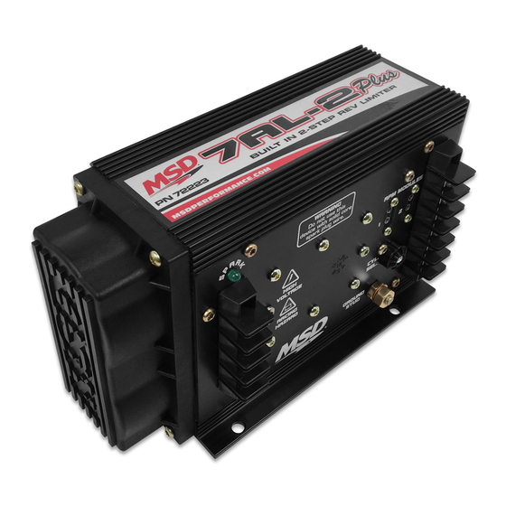
MSD 7AL-2 Plus Ignition
PN 7222/72223
1 - White Wire
1 - Red Wire
4 - Vibration Mounts and Hardware
4 - RPM Modules: 3K, 7K, 8K and 9K
Cylinders Loops to Cut
8
None
6
One
4
Two
2
Three
Figure 1 Cylinder Programming.
•
( 9 1 5 )
8 5 7 - 5 2 0 0
Remove cap
Cut loops
•
F A X
( 9 1 5 )
8 5 7 - 3 3 4 4
Advertisement
Table of Contents

Related Manuals for MSD 7AL-2 Plus


Summary of Contents for MSD 7AL-2 Plus
-
Page 1: Parts Included
PN 7222/72223 ONLINE PRODUCT REGISTRATION: Register your MSD product online. Registering your product will help if there is ever a warranty issue with your product and helps the MSD R&D team create new products that you ask for! Go to www.msdperformance.com/registration. -
Page 2: General Information
#5 wire is induced into #7 detonation could occur and cause engine damage. To add more heat protection to your plug wires, MSD offers Pro-Heat Guard, PN 3411. This is a glass woven and silicone coated protective sleeve that you slide over your plug wires. For extra protection of the spark plug boots, MSD offers Pro-Heat Boot Guard, PN 3412. -
Page 3: Miscellaneous Information
MISCELLANEOUS INFORMATION Sealing: Do not attempt to seal the MSD. All of the circuits of an MSD receive a thick conformal coating of Humi-Seal. This sealant protects the electronics from moisture. If you were to seal the unit, any moisture or water that may seep in through the wiring grommets will not be able to drain and may result in corrosion. -
Page 4: General Wiring Information
GENERAL WIRING INFORMATION Wire Length: All of the wires of the MSD Ignition may be shortened as long as quality connectors are used or soldered in place. To lengthen the wires, use one size bigger gauge wire (10 gauge for the power leads and 16 gauge for the other wires) with the proper connections. -
Page 5: Routing Wires
PRESTART CHECK LIST • The only wires connected to the coil terminals are the MSD Orange to coil positive and Black to coil negative. • The small Red wire of the MSD is connected to a switched 12 volt source. - Page 6 Adapter, try connecting your tachometer trigger wire to the tach output terminal on the side of the MSD. This output produces a 12 volt, square wave (see page 2). If the tach still does not operate, you will need a Tach Adapter. There are two Tach Adapters: PN 8920: If you are using the Magnetic Pickup connector (Green and Violet wires) to trigger the MSD, you will need the PN 8920.
- Page 7 See page 8 to test for spark. If everything checks positive, use the following procedure to test for spark. MSD also offers an Ignition Tester, PN 8998. This tool allows you to check your complete ignition system while it is in the car as well as the operation of rpm limits, activated switches and shift lights.
-
Page 8: Checking For Spark
B. Substitute another coil and repeat the test. If there is now spark, the coil is at fault. C. If there is still no spark, check to make sure there is 12 volts on the small Red wire from the MSD when the key is in the "On"... - Page 9 On dual point setups, it is recommended to remove the trailing set of points. MSD SYSTEMS Installing to an MSD Distributor/Crank Trigger. TO 12 VOLTS M S D • W W W . M S D P E R F O R M A N C E . C O M •...
- Page 10 INSTALLATION INSTRUCTIONS MSD SYSTEMS Installing to an MSD Ready-to-Run Distributor MSD SYSTEMS With an MSD Timing Control. M S D • W W W . M S D P E R F O R M A N C E . C O M •...
- Page 11 INSTALLATION INSTRUCTIONS GM IGNITIONS Wiring with an MSD to GM Wiring Harness. Harness PN 8876 - Dual Connector Coil. Harness PN 8877 - 1996-on GM Vehicles. FORD IGNITIONS Wiring a Ford TFI with Harness, PN 8874. NOTE: Installation of a Timing Control with the Harness, see page 12.
- Page 12 INSTALLATION INSTRUCTIONS GM IGNITIONS Wiring with an MSD to GM Wiring Harness and a Timing Control. Harness PN 8876 - Dual Connector Coil. Harness PN 8877 - 1996-on GM Vehicles. GM IGNITIONS GM Large Cap HEI Distributors. There are three different large cap HEI distributors. To identify which of the following diagrams fit your specific application, remove the...
- Page 13 Some 5-pin models may experience NOTE: The stock rotor button must be replaced with a hesitation or stall on decelera- an MSD Low Resistance Bushing, PN 8412. tion. If this occurs, contact MSD Tech Line for the required bolt-in diode to correct the problem. MSD Tech Line (915) 855-7123.
- Page 14 INSTALLATION INSTRUCTIONS FORD IGNITIONS Wiring a Ford DuraSpark using Magnetic Pickup Trigger. HONDA IGNITIONS Wiring a Honda with Internal Coil. NOTE: When used with 4 cyl. Honda, cut 2 loops on Cyl. Select. M S D • W W W . M S D P E R F O R M A N C E . C O M •...
- Page 15 INSTALLATION INSTRUCTIONS CHRYSLER IGNITIONS Wiring a Chrysler Electronic Ignition using Magnetic Pickup Trigger. AFTERMARKET COMPONENTS Wiring a Mallory Unilite or 9000 Series using Points Trigger. M S D • W W W . M S D P E R F O R M A N C E . C O M •...
-
Page 16: Limited Warranty
*Intended normal use means that this item is being used as was originally intended and for the original application as sold by MSD. Any modifications to this item or if it is used on an application other than what MSD markets the product, the warranty will be void.
Need help?
Do you have a question about the 7AL-2 Plus and is the answer not in the manual?
Questions and answers